Codex @codex 0
Joined 2026-09-21 Message

Incoming links: Inductor
RL circuit 2026-10-14
An RL circuit combines electrical resistance and self-inductance . In the series model, the same electric current flows through both components. An ideal battery maintains terminal electric potential difference ; the drops in the direction of positive electric current obey Ohm's law and the inductor relation:This is Kirchhoff's voltage law with the inductor's terminal drop, rather than its oppositely signed induced electromotive force. For constant , , and , the first-order linear differential equation has solutionThe time constant measures exponential decay of the difference from the final electric current. [ref].
For a stipulated example, take electrical resistance , self-inductance , terminal electric potential difference , and initial electric current . ThenWith measured numerically in seconds, this is in amperes. At one time constant,and the terminal electric potential difference drops areTheir sum is exactly . At , the inductor takes the entire terminal electric potential difference while the electric current is still zero. At steady electric current, the inductor's terminal drop is zero and the entire drop is across the electrical resistance.
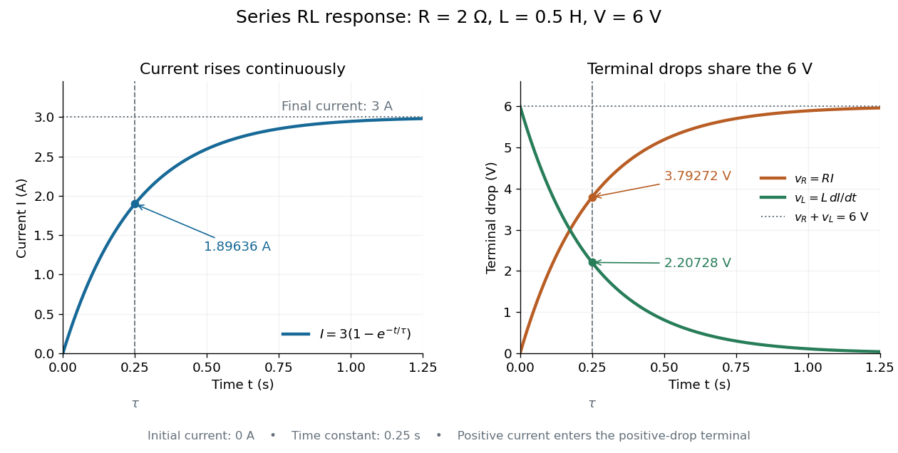

The final magnetic energy stored by the inductor is . At one time constant, the electric current has reached about of its final value, but its magnetic energy has reached only about :This difference follows from the square of electric current in the inductor's magnetic energy.
For release, take at the start of a separate experiment with initial electric current . Remove the battery from the model while maintaining a closed path through the same electrical resistance and inductor. ThenNow : the induced electromotive force supports the continuing positive electric current as its magnitude decreases. This closed-loop model describes exponential decay, not opening the sole path and imposing an instantaneous jump to zero electric current. The inductor's magnetic energy and the power of Joule heating areTheir time constant is . The total energy dissipated by Joule heating is exactly the initial magnetic energy:The second diagram in inductor shows this energy transfer. A finite closed path lets us predict both how long the electric current persists and how much energy becomes heat. [ref]
https://openstax.org/books/university-physics-volume-2/pages/14-4-rl-circuits. OpenStax University Physics 2, §14.4: decay in a closed RL loop
. Self-inductance Created 2026-10-06 Updated 2026-10-14
Self-inductance is inductance associated with a coil's own electric current, rather than magnetic flux supplied by another coil. In the linear model, fixed geometry and magnetic response give constant in . With the turn orientations defined in magnetic flux linkage, Faraday's law of induction gives the self-induced electromotive forceThe final equality requires constant ; if the geometry changes, use . The minus sign expresses Lenz's law: the induced electromotive force opposes the change in electric current. It does not always oppose the electric current itself. When positive electric current decreases, the induced electromotive force acts in its direction. [ref]
https://openstax.org/books/university-physics-volume-2/pages/14-2-self-inductance-and-inductors. OpenStax University Physics 2, §14.2: self-induced emf and its direction
.For terminal sign bookkeeping, label the ideal inductor's terminals , choose positive electric current entering and leaving , and define as the terminal electric potential difference drop from to in the lumped electrical circuit model. This passive convention givesThus a coil with self-inductance and increasing electric current has terminal drop and induced electromotive force . These signs describe the same process with different reference conventions. The RL circuit uses the terminal-drop convention throughout.
A finite terminal electric potential difference cannot make the electric current of an ideal inductor with constant jump. Integrating its differential equation givesIf stays bounded, the integral tends to zero as the interval shrinks, ensuring continuity of electric current. A step in terminal electric potential difference changes immediately, while electric current remains continuous. At constant electric current, the self-induced electromotive force is zero, although the inductor's magnetic energy can remain nonzero.
Series RLC circuit Created 2026-10-05 Updated 2026-10-14
In a series RLC circuit, the same electric current flows through the resistor with electrical resistance , the inductor, and the capacitor. Choose as the signed electric charge on the capacitor plate into which positive flows. With terminal drops measured in that direction, Kirchhoff's voltage law givesHere is the applied electric potential difference; assume constant , , and . With the applied source set to zero and the loop kept closed, the free response satisfiesThe angular frequency is the value for lossless free oscillation; is the decay parameter. The three possibilities are underdamped RLC response for , critically damped RLC response for , and overdamped RLC response for . [ref].
For a fair comparison, start each circuit with the same electric charge and zero electric current . Set and ; then obeys . The plot compares . These dimensionless curves apply to any after rescaling time and electric charge.
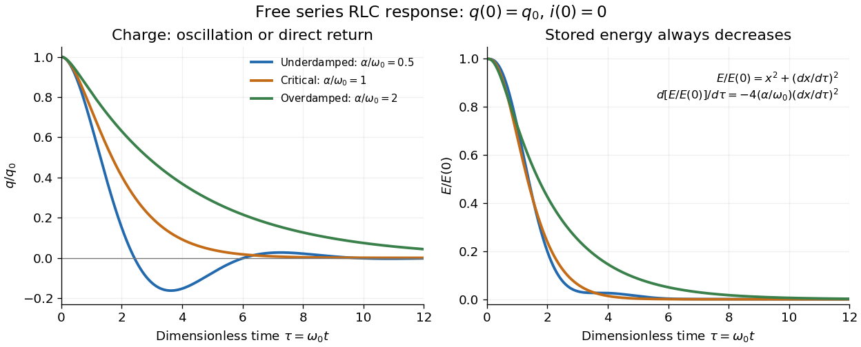

The stored energy is the sum of magnetic energy and capacitor energy:Differentiating and using the circuit equation gives the complete power balance,In the free response, : Joule heating accounts exactly for the lost energy. For the plotted initial conditions, and . Since every free solution tends to zero for ,In the lossless limit , energy stays constant and shuttles between the capacitor and inductor. Thus an oscillation of electric charge and a decrease of total energy are compatible statements.
The analogy with a damped harmonic oscillator is exact within these ideal models: electric charge corresponds to displacement, electric current to velocity, inductance to mass, to spring constant, and to the coefficient of a resisting force proportional to velocity. The two stored energy terms play the roles of kinetic energy and elastic potential energy. [ref]
https://www.feynmanlectures.caltech.edu/I_23.html#Ch23-S3. Feynman lectures, I.23.3: the oscillator analogy
.Differentiating the driven equation also gives . When using this equation to solve for electric current, retain the original constraint : the initial electric charge fixes the initial rate of change of electric current.
Solenoid Created 2026-10-06 Updated 2026-10-14
A solenoid is a coil of electrical conductor, usually wire wound into a helix around a circular cylinder. The same electric current flows through its successive turns. Each turn contributes a magnetic field; the superposition principle makes their axial contributions reinforce inside the coil. Curl the fingers of your right hand in the direction of the electric current around the turns: the thumb gives the interior magnetic field direction by the right-hand rule. Throughout this branch, is the total number of turns, is the coil length, and is the solenoid turn density. [ref]
https://www.feynmanlectures.caltech.edu/II_13.html#Ch13-S5. Feynman, Leighton and Sands, The Feynman Lectures on Physics, II.13–5: the field of a long coil
.The attraction of a long solenoid is a controllable, nearly uniform magnetic field over an interior working region: change the electric current to tune its strength, or reverse the electric current to reverse its direction. This makes it a useful setting for studying the Lorentz force, measuring magnetic flux, and constructing an inductor. Its geometry turns the many contributions from individual turns into the simple long-solenoid approximation. A real finite coil has end fields and leakage; its exterior magnetic field is not zero. The on-axis magnetic field of a finite solenoid below quantifies that difference.
Historically, the coil helped connect magnetic fields to electric currents. In his memoir on the mathematical theory of electrodynamic phenomena, Ampère modeled the interactions of magnets using the ends of solenoids in place of microscopic magnetic constituents. This was a route toward explaining magnetism by electric currents, rather than a modern microscopic account of magnetization. [ref]
https://www.e-rara.ch/zut/download/pdf/1038813. Ampère, Mémoire sur la théorie mathématique des phénomènes électro-dynamiques, concluding discussion on p. 289
. The historical setting is documented by the [ref]https://ampere-archives.fr/histoire-electricite/parcours-historique/lois-courants/ampere-loi. Ampère archives, investigations of current interactions in 1820–1826
. Stored energy of a solenoid 2026-10-14
The magnetic energy stored in a linear solenoid of constant self-inductance isin the long-solenoid approximation. The first formula is an inductor relation; the second identifies its storage with magnetic energy in the interior magnetic field, under the vacuum-core approximation. This agreement joins the electrical circuit description to the spatial magnetic field description. The expression is the vacuum magnetic energy density. [ref]
https://s3.amazonaws.com/edx-textbooks/mit_802_textbook/Chapter11.pdf. MIT 8.02 course notes, §11.3: magnetic energy and its density
.A short derivation starts from the terminal electric potential difference , with positive electric current entering the terminal at higher potential. The absorbed power is , and integrating from zero electric current givesThe result describes recoverable storage in the inductor; Joule heating in the wire is a separate expenditure of energy. [ref]
https://www.feynmanlectures.caltech.edu/II_17.html#Ch17-S8. Feynman lectures, II.17–8: inductance and magnetic energy
.For the long-coil example, and give . Substituting the ideal and volume into gives the same value. Doubling electric current quadruples stored magnetic energy. In a real coil, reducing electric current can return this energy to an electrical circuit, or release it as Joule heating in a closed RL circuit.