For an axially symmetric rotational Lagrangian with potential , fixed tilt and conservation of the spin and azimuthal momenta give constant precession. The tilt equation becomes . A real precession rate requires the quadratic discriminant to be nonnegative. The inertia and height parameters must correspond consistently to the chosen fixed point.
Expanding the squared velocity and integrating over mass removes the mixed term because the centre-of-mass first moment is zero. The remaining rotational integral is half the scalar product of angular velocity and angular momentum about the centre of mass. Principal axes diagonalize that rotational quadratic form.
An ideal circular ring whose mass lies at a single radius from its symmetry axis. About that axis, the moment of inertia is . The result assumes negligible radial and axial thickness; it is different from the of a uniform solid disk.
A thin straight rod of length , mass , central moment of inertia and midpoint centre of mass starts beside a pointlike pole at that midpoint. An end impulse perpendicular to the rod gives translation and rotation . At the first quarter-turn the trailing end is at horizontal distance from the pole. Strict clearance requires ; equality is the grazing limit. The criterion is for free motion before contact, a negligibly thin rod and pole, and an impulse directed away from the pole.
A vehicle with centre of mass midway between level rails separated by d, at height h, follows a turn of radius R. Vertical force balance and cross-sectional moment balance give inner rail reaction . Its first zero occurs at the displayed speed. This is a toppling criterion under maintained lateral contact, not a guarantee against sliding or suspension instability.
A rigid body undergoes translation when every point has the same displacement at each time, so its orientation stays fixed. For a freely moving system of particles coupled only by internal springs, the common displacement is a zero-frequency normal mode: internal spring lengths and potential energy are unchanged. Its mode coordinate is , representing constant centre-of-mass velocity, rather than an oscillation at nonzero frequency.
The instantaneous velocity of the material point of a rigid body touching another body. In the displayed formula, is its position relative to the centre of mass, and is the body's angular velocity. The rotational term is a cross product. This material-point velocity differs from the motion of the geometrical contact location: in rolling without slipping on a stationary plane it vanishes even while the contact location advances. For a sphere touching a horizontal plane, with rightward centre velocity and anticlockwise spin , its tangential component is .
An ideal elastic collision between a sphere and a stationary plane reverses normal approach velocity. On the fully rough, tangentially elastic branch, the tangential contact-point velocity reverses too. If is the signed tangential impulse, translation and spin obey and , with positive spin anticlockwise. Restoring tangential translational plus rotational kinetic energy givesThe nonzero root is the displayed impulse; the other root is the smooth-contact branch. For , the map is and . It preserves kinetic energy and the angular momentum about the contact point, . An unspecified rough surface need not realize this idealization: finite friction or a dissipative tangential contact law requires additional constitutive data. Setting the outgoing contact slip to zero instead loses of kinetic energy for this uniform sphere.
A short transverse impulse at lever arm gives a pivoted rigid body angular velocity and contact-point velocity , where is its pivot moment of inertia. Thus plays the role of a translational mass in the impact direction. A point projectile elastically striking an initially stationary body stops immediately after impact precisely when its mass equals this effective value. The pivot can exchange linear momentum while doing no work.
A normal impulse on a free planar rigid body of mass and moment of inertia , at perpendicular lever arm , changes the contact point's normal velocity by . Its effective mass in that direction is therefore . This follows by adding the translational change to the rotational contribution .
For an incoming point mass , the inverse reduced contact mass is . A smooth elastic collision with initial relative approach speed has impulse , since the relative normal velocity reverses. This separates effective inertia at a contact from the body's total mass and explains the lever-arm dependence in an equal-speed elastic impact on a free rod.
When material sticks to a rotor, the incoming angular momentum flux and external torque obey . With zero incoming axial angular momentum and zero external axial torque, is constant. For deposition at fixed radius at mass flow rate , and the rotational kinetic energy satisfies . This loss is the irreversible cost of bringing the incoming material up to tangential speed; it does not violate conservation of angular momentum.
Let a bell have axial moment of inertia and centre of mass h from its axle. A clapper of point mass m at radius l touches the bell at fixed relative angle . While they remain in contact, the clapper angle from the upward vertical obeys . The contact force opposing increasing angle is . Eliminating the acceleration givesThe first zero on the physical trajectory marks detachment, because a nonadhesive contact cannot support negative normal force. Selecting the correct trigonometric branch is part of the contact problem.
At fixed angular momentum, rotational energy is minimized by rotation about the largest principal moment of inertia. Indeed, . Weak internal dissipation can therefore relax a nearly rigid isolated body towards that axis. A perfectly rigid torque-free body conserves energy and does not settle; both extreme-inertia axes are stable in its ideal dynamics. The maximum-inertia axis need not be the geometrically longest axis.
For a body constrained to rotate about a fixed pivot, a perpendicular impulse delivered at distance from the pivot produces . If the centre of mass is distance from the pivot, its momentum is . The pivot impulse is , and vanishes when . This impact location is the centre of percussion. The result assumes the stated planar rigid-body geometry and a short impulse; it is not a claim that all forces at the pivot vanish afterward.
For a uniform square plate of side hinged along an edge, and . An impulse normal to the plate, applied a distance below the centre, gives and signed hinge impulse . Therefore the hinge impulse vanishes at below the centre, a distance from the hinge. The sign of identifies the reaction direction; its magnitude is .
The net external torque about an inertial origin equals the time derivative of angular momentum. For rotation about a fixed axis with constant moment of inertia, its axial component reduces to .
A rigid body with moment of inertia , constant driving power and linear resisting torque has an exponential approach of to . The ideal drive requires torque , so starting from rest is a limiting energy model with singular initial torque.
For a rigid vehicle turning on a level road, with centre of mass height , half track width and turn radius , sufficient static friction supplies centripetal acceleration . The inner and outer wheel normal forces obey and . The inner contact force first vanishes at the displayed speed. The approximation neglects suspension movement and extra torques; inadequate static friction can cause sliding before rollover.
Two identical uniform rigid bodies of rod shape, each of length and mass , form a symmetric arch with a free common hinge and both outer ends sliding without friction on a horizontal floor. At angle , each center has speed , giving total kinetic energy . The total gravitational potential energy is . Conservation of energy from rest at gives the displayed hinge impact speed. Unlike fixing one outer endpoint, allowing both endpoints to slide keeps the arch center horizontally fixed. The floor reaction on each rod is , nonnegative throughout this fall.
Each massless rod has endpoint masses at distance from its centre, hence total mass and moment of inertia . In a symmetric opposite-end collision with centres approaching at speed , a horizontal impulse changes each centre speed by and each contact-point speed by . The coefficient of restitution gives . Both rods rotate in the same sense for the staggered vertical configuration; their centre speeds after impact are .
// Target: electromagnetism.bigb
Two equal uniform rods of length and mass , one pivoted to the floor and the other endpoint sliding on it, have arch coordinates and . The kinetic energy decomposition about the center of mass gives , while gravitational potential energy is . Conservation of energy from rest at angle gives the displayed equation and hinge impact speed , provided contact is maintained. The endpoint's normal reaction becomes negative during this constrained fall if ; a unilateral floor then permits detachment and the constrained formula no longer describes the entire motion.
In solid-body rotation the angular velocity is independent of distance from the rotation axis, so tangential speed is proportional to cylindrical radius. A galactic region with this galaxy rotation curve has radial epicyclic frequency .
A symmetric top is a rigid body with two equal principal moments of inertia, conventionally . Its third principal axis is its symmetry axis.
Consider a symmetric top with fixed vertex , axial unit vector , principal moments of inertia , and centre of mass at . Let a force act at , where is the upward vertical unit vector. Together with gravity, it produces torque and potential energy .
The axial angular velocity of a symmetric top , vertical angular momentum and total mechanical energy are conserved. For steady precession, and . Substituting into gives the condition in the title for nonvertical inclination. If the total angular velocity itself is , then , and the condition becomes .
For a symmetric top with axial unit vector and angular velocity , the classical axial spin is the scalar . The identity implies . If the transverse and axial principal moments of inertia are and , then the angular momentum about the fixed vertex is . A torque perpendicular to conserves . During steady precession at rate and inclination , the general angular velocity is ; the precession rate by itself does not fix .
Let a symmetric top have principal moments of inertia and . Apply a torque constant in a principal body frame. Then the axial angular velocity is a conserved quantity. Define and . The first two of Euler's equations combine into the equation in the title. This derivation uses constancy in the principal body frame, which generally does not mean constant torque in an inertial frame.
Multiplying by the integrating factor proves, for ,Equivalently rotates about the constant point in the complex transverse plane. When , the solution is instead . The angular velocity is .
A rotor with two equal transverse moments and a smaller symmetry-axis moment, . Its rotational constants obey .
An oblate symmetric top has two equal smaller principal moments of inertia and a larger moment of inertia about its symmetry axis. A planar trigonal molecule, such as boron trifluoride, is an example. Its axial rotational constant is smaller than its transverse rotational constant.
For an axially symmetric rigid body with and , no external torque means that angular momentum is fixed in an inertial frame. The axial angular velocity is constant by Euler equations for a torque-free rigid body, and the symmetry axis obeysIts angle to is constant and it precesses in space at . The transverse angular-velocity components instead rotate in body coordinates at signed rate . These are different frame descriptions and must not be substituted for one another.
For principal inertias , the transverse angular-velocity components rotate in body axes at signed rate . The symmetry axis precesses about the inertially fixed angular momentum at rate . These are different frame-dependent descriptions of the same motion.
A heavy symmetric top is a symmetric top with one point fixed in a uniform gravitational field. Its vertical and body-axis rotational symmetries give two cyclic Euler angles.
After fixing the two cyclic angular momenta of a heavy symmetric top, its inclination has an effective potential with . Write the reduced energy equation in the form . A steady nonvertical inclination has and , the latter coming from the reduced second-order Euler-Lagrange equation. Therefore .
This proves the double-root condition without dividing by a velocity that vanishes in the very solution under study. A simple turning point has but nonzero derivative, and is not a steady inclination. Exactly vertical spinning corresponds to , where the inclination coordinate and its reduced denominator are singular; these endpoint configurations require a separate treatment and do not supply an interior double root.
Writing the unit symmetry axis as and axial spin momentum as , angular momentum is . Taking its derivative and applying gravitational torque gives .
Variation in the inclination of a rotating body's axis, distinguished from its azimuthal precession. For a heavy symmetric top, the cyclic angular momenta reduce the motion to with and cubic. Its admissible interval and turning points describe the nutation.
A heavy symmetric top precesses uniformly when its inclination is constant and its azimuthal speed is constant. For a nonvertical inclination, the condition is . The real-root condition depends on whether the body axis points above or below the horizontal.
When , the two nonvertical steady-precession roots are approximately and . These asymptotic descriptions do not apply at a singular denominator without taking the original quadratic limit.
Precession is the rotation of a body's spin axis about another direction, such as the vertical or the conserved angular-momentum vector.
The time for a precessing orientation to turn through . An unlabelled line is unchanged by a turn, so its visible pattern can repeat after half the full precession period.
Angular velocity is the vector whose direction gives the instantaneous rotation axis and whose magnitude gives the angular speed.
Angular acceleration is the time derivative of angular velocity, . For rotation about a fixed axis, its signed scalar component obeys when the axial moment of inertia is constant and is the total applied torque about that axis.
Angular speed is the nonnegative magnitude of angular velocity: . It measures the rate of rotation about an instantaneous axis without specifying its direction. For uniform circular motion of radius , the ordinary speed is .
A principal body frame is an orthonormal basis fixed in the body and aligned with the principal axes of its inertia tensor. In this frame the inertia tensor is diagonal with principal moments .
A principal axis is an eigenvector direction of the inertia tensor. Choosing three orthogonal principal axes diagonalizes the inertia tensor.
If a vector is fixed in space while a body frame rotates with angular velocity , its body-frame components satisfy
In principal body coordinates, Euler's equations express angular momentum balance as , with applied torque . Setting the torque to zero gives the following torque-free specialization.
The Euler equations for a torque-free rigid body conserve rotational kinetic energy and squared angular momentum,Their common level sets are the intersection of two ellipsoids in angular-velocity space.
Eliminating and between the conserved energy and squared angular momentum givesThe right-hand side is a quartic polynomial in ; its real turning points delimit the nutation of the body-frame angular velocity.
For principal moments and symmetry-axis unit vector , angular momentum and angular velocity obeyThus , , and the symmetry axis are coplanar at every instant.
For a rigid body with three distinct positive principal moments of inertia and zero external torque about its centre of mass, steady rotation about the first or third principal axis is Lyapunov stable in angular velocity, while rotation about the intermediate principal axis is unstable. Here steady rotation means in the principal body frame, with constant . A small sideways perturbation remains small about the extreme principal moments of inertia, but generically grows about the intermediate one. Stable does not mean that the wobble decays: without damping, there is no asymptotic stability. Coincident principal moments of inertia and a stationary body are excluded.[ref]
3. The Motion of Rigid Bodies. Classical Dynamics by David Tong, §3.4.3, The Asymmetric Top: Stability, printed pp. 57–58, equations (3.40)–(3.45)
No external torque is needed for a body to tumble. Conservation of angular momentum fixes in the fixed space frame, but the body can turn relative to , so its angular velocity components in the principal body frame change. The torque-free rigid-body invariants constrain this motion. A supported gyroscope with gravitational torque has different governing assumptions.
For torque-free rotation, total angular momentum magnitude and rotational kinetic energy are conserved. Near rotation about principal axis three, eliminate from to obtain the displayed energy difference from . If is largest, it is a constrained energy minimum; if smallest, a maximum. Both extrema are stable in the conservative problem. An intermediate moment gives opposite signs in the quadratic form, a saddle and instability. Dissipation changes the fixed-energy argument and must not be silently added to torque-free motion.
Choose an inertia unit and an angular speed unit , so physical principal moments of inertia are , physical angular velocity is , and normalized time is . The Euler equations for a torque-free rigid body becomeThis is a physically admissible ideal planar mass distribution: is the perpendicular axis theorem. A book of finite thickness need not have these exact ratios.
For an original comparison, start with angular velocity , or , respectively. With , the transverse Euclidean norm stays small about axes one and three, but becomes order one about axis two. For the intermediate-axis start, its linearization givesThe hyperbolic functions contain a growing exponential function with rate . Reducing tenfold delays reaching the same small transverse amplitude by approximately normalized time units, once the growing term dominates. That delays the instability. Once the transverse angular velocity is comparable to the main component, the linearization ceases to describe the motion.
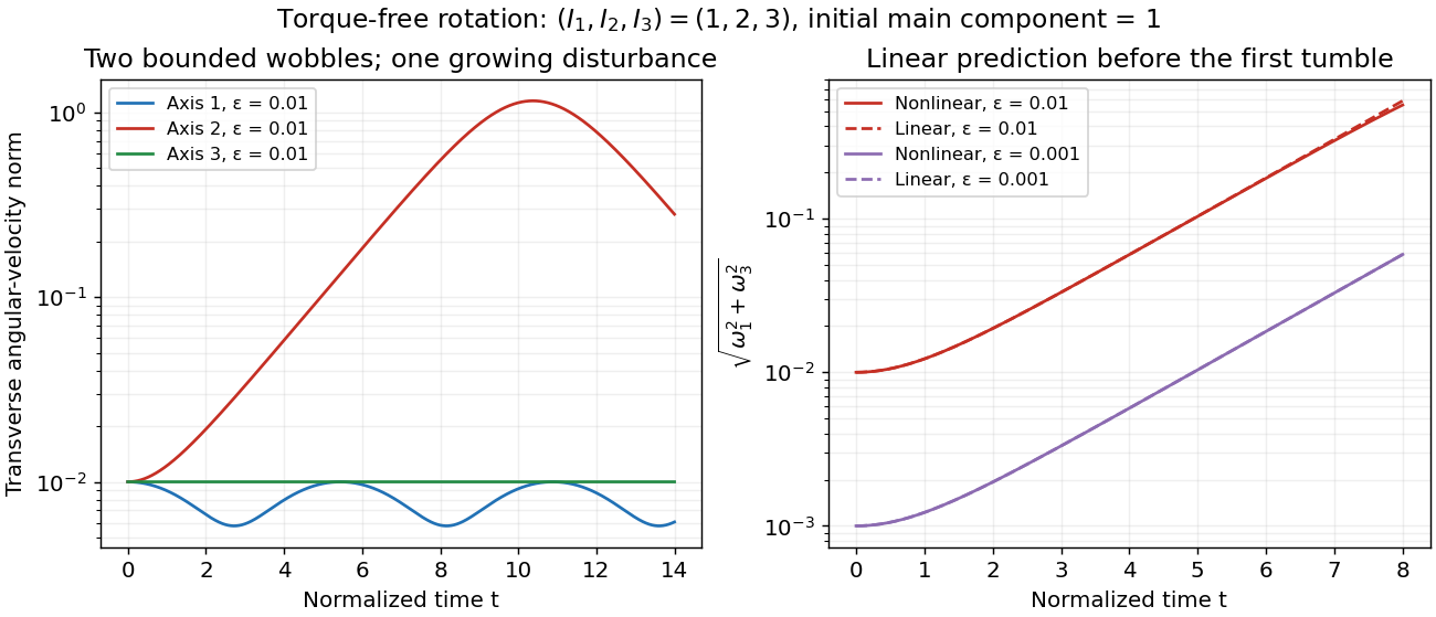
Small perturbations about the three principal axes
. Original Runge-Kutta method calculations for the normalized intermediate-axis model, with initial angular velocity , and . Left: transverse Euclidean norm relative to each initial principal axis. Right: full Euler equations for a torque-free rigid body compared with the displayed linearization, also using . Dashed curves are linear predictions. These are model curves, not measured throws. Details.A useful readout of a tumble is the alignment of the intermediate principal axis with the conserved angular momentum direction . In the principal body frame, write and . ThenA change from to means that the directed body axis has turned nearly relative to . It does not mean that reversed in the fixed space frame. The unsigned line through that principal axis hides this distinction, so a marked end matters in an actual demonstration.
For the normalized intermediate-axis model with , the rotational kinetic energy and squared angular momentum are and . Hence : this initial condition lies close to, but off, the intermediate-axis separatrix. An independent calculation evolves and a rotation matrix taking body components to space components. The intermediate principal axis crosses at normalized times approximately and , alternating long nearly aligned intervals with quicker reversals.
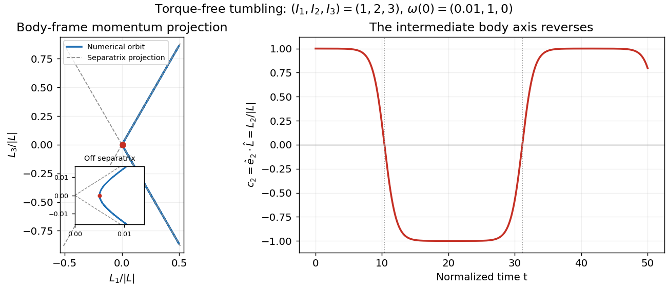
Torque-free reversals of a nearly aligned body axis
. Original independent Runge-Kutta method calculation in angular momentum and rotation matrix variables, starting with in the normalized intermediate-axis model. Left: body-frame orbit projected onto ; dashed lines are the intermediate-axis separatrix projections . The red point is the initial condition; the inset resolves its separation from those lines. Right: , with dotted lines at the first two zero crossings. The full angular momentum vector remains fixed in space. Details.Both calculations use step size without rescaling either invariant. Over , the tumbling calculation changes rotational kinetic energy and squared angular momentum by less than relative to their initial values. Reconstructing in the fixed space frame gives relative error below . Halving the step changes the body components and rotation matrix entries by less than . These checks distinguish physical tumbling from numerical drift. On the exact intermediate-axis separatrix, approach to an intermediate-axis rotation takes infinite time; the recurrent off-separatrix example here is different.
Clemson's documented apparatus is a book held tightly closed with several rubber bands. Toss it freely with spin about each principal axis in turn: the stated visual readout is steady orientation for the smallest and largest principal moments of inertia, but a flip before the catch for the intermediate one. The same book and the two extreme-axis throws provide comparison controls; the bands support the rigid body approximation by restraining the pages. This is a documented qualitative demonstration, not a measurement of .[ref]
Spinning Book by Clemson University. Spinning Book by Clemson University, physics lecture demonstrations, 1Q60.40: Purpose, Description and Equipment
For a rectangular book with length , width and thickness , where , a uniform mass model gives principal moments of inertia , and . The intermediate principal axis runs across the width through the centre of mass; the maximum is normal to the cover. A marked cover or end helps distinguish ordinary spin from reversal of a directed body axis.
Interpret only the interval after release and before the catch: hand contact applies torque, whereas gravity in a uniform gravitational field has zero net torque about the centre of mass because . Air resistance, page motion, an imperfect release and short flight limit the approximation. A toss ending before the perturbation grows need not reveal instability. Comparable initial angular speeds and flight durations would improve the comparison; these are suggested controls, not quantified controls reported by Clemson.
For , the transverse linear stability rates about steady rotation with signed component areAxes one and three have transverse eigenvalues and , producing bounded oscillations. Axis two has transverse eigenvalues , giving growing and decaying exponential functions. A neutral longitudinal perturbation corresponds to a small change of . Generic intermediate-axis disturbances contain a growing component; a precisely chosen decaying direction is exceptional. For the normalized intermediate-axis model with , the values are , and .
Proof outline: the linearization of the Euler equations for a torque-free rigid body about the third principal axis gives transverse perturbations obeyingand henceCyclic permutation gives the other rates. For nonlinear Lyapunov stability of the extreme rotations, use the torque-free rigid-body invariants: the conserved quadratic forms and have strictly positive transverse coefficients about axes one and three respectively. They bound transverse angular velocity, while bounds its longitudinal change near nonzero rotation. Imaginary transverse eigenvalues alone would not establish this nonlinear conclusion.[ref]
The practical lesson is to choose a stable principal axis when using rotation to maintain an instrument's pointing direction. Both extreme principal moments of inertia are stable in the ideal torque-free model; if internal damping lowers rotational kinetic energy while approximately preserving angular momentum, the minimum energy instead favors the largest principal moment of inertia. A control system must account for torque, changing mass distributions and flexibility before applying this ideal result.
On the invariant level , the torque-free rigid-body orbit is a separatrix joining the two intermediate-axis rotations. Withone orientation has ; the other components are constant multiples of .
The moment of inertia about a specified axis measures how a mass distribution resists changes of angular velocity about that axis. For point masses at perpendicular distances , or a continuous distribution with mass density ,Its SI unit is . The distance is to the entire axis, not to one point on it: moving a point mass along the axis leaves its contribution unchanged. The moment of inertia depends on both the distribution and the chosen axis; it is not determined by total mass alone. About an axis fixed in an inertial frame, a rigid body with larger moment of inertia has smaller angular acceleration under the same net axial torque, and greater rotational kinetic energy at the same angular speed.[ref]
For a simple model, put four equal point masses of total mass on light rigid spokes at radius . Their moment of inertia is . Doubling quadruples the moment of inertia without changing . The illustrated placements and give and . Actual spokes and finite-sized weights contribute their own moments of inertia; the point mass model neglects them. Repositioning weights during rotation also breaks the fixed-distribution assumption, so it requires a separate work and angular momentum calculation.
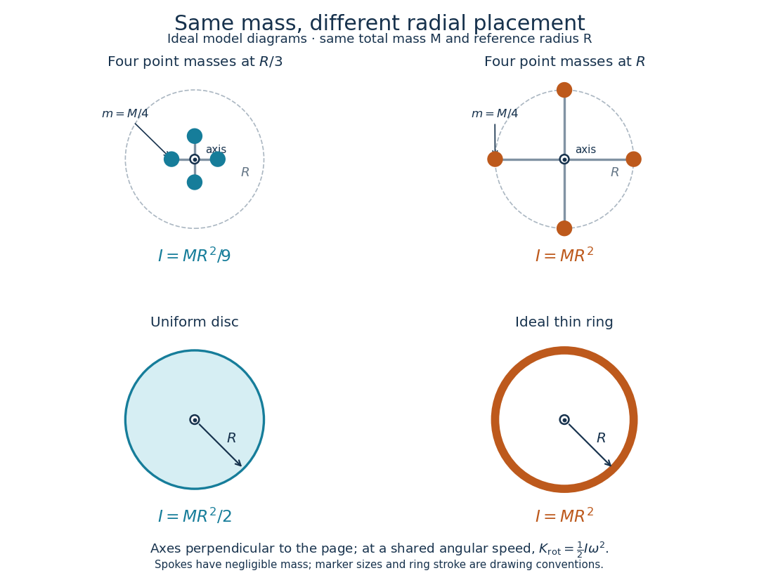
Same total mass, different radial placement and moment of inertia
. Original model diagrams, not experimental data. The upper pair has four equal point masses on negligible-mass spokes, at and from a perpendicular central axis. The lower pair compares a uniform disc with an ideal thin ring of the same mass and outer radius . The displayed moments of inertia determine rotational kinetic energy at a shared angular speed. The visible thickness of the ring and size of the point markers are only drawing conventions. Details.The moment of inertia of a uniform disc follows by dividing it into concentric annuli: and . For an ideal thin ring every mass element is at , so . A ring of finite radial thickness instead uses the moment of inertia of a uniform annulus, , with inner radius . A moment of inertia is thus a compact summary of radial placement rather than a complete description of shape. For several joined pieces, their moments of inertia add only when each is calculated about the same axis.[ref]
A physical pendulum makes the moment of inertia measurable through timing. Martín Monteiro, Cecilia Stari, Cecilia Cabeza and Arturo C. Martí used a metal bar with suspension holes apart and an attached smartphone. They report bar length , bar mass and phone mass . Changing the suspension hole changes the pivot axis. Their readouts were phone gyroscope angular velocity records, analyzed by autocorrelation or a fit to a sinusoid, and an independent photogate; the logged records for the sinusoid fits lasted . They observed agreement between the three timing methods and the geometry-based model, including a minimum of oscillation period as the suspension point varied. These are reported apparatus details and observations, not measurements made for this article.[ref]
To infer a moment of inertia from such a measurement, determine the total mass including every attached part, locate the assembly's centre of mass , and measure its distance below the horizontal pivot . Record successive crossings in the same direction, or the elapsed time for complete oscillations, giving oscillation period . The physical pendulum model with a fixed pivot, a uniform gravitational field, negligible friction and the small-angle approximation givesThe crossing times, masses and geometric distances are the measured inputs; is an inference conditional on this model, while an integral over the assumed shape supplies an independent model prediction. The parallel axis theorem converts the inferred pivot moment of inertia to one about a parallel axis through . The controls and interpretation of that comparison are described there. An axial measurement determines one scalar moment of inertia, not the complete inertia tensor needed for general rotation.
A uniform disk of radius and area mass density has a circular hole of radius , whose centre H is displaced by from the original centre C. Set , and . The parallel axis theorem gives . Removing the material shifts the remaining centre of mass G away from H by , so and . Thus the rotational component of free rigid-body kinetic energy is smaller than fixed-axis kinetic energy about H at the same angular speed, although total rolling kinetic energy also includes translation.
Integrating over a uniform-density spherical layer gives the displayed result. It becomes for a solid sphere and tends to only in the thin-shell limit. Calling a layer hollow does not make its thickness negligible.
For a solid cylinder with mass density and , integrating cylindrical shells gives and axial moment of inertia . Their ratio proves the displayed formula. It gives the uniform-cylinder result at p=0 and at p=2. The radial density weighting must enter both mass and inertia integrals.
For a cylinder of uniform mass density , length , inner radius and outer radius , an annular element has . Thus the axial moment of inertia is . Dividing by yields the displayed result. At fixed mass, the solid-cylinder limit is and the thin-shell limit is .
A uniform solid with circular cross-sectional radius can be sliced into thin discs. A slice of thickness has mass and axial moment of inertia . ThusAll slice axes coincide, so no parallel axis theorem correction is needed. For a linearly tapered section of length with end radii , direct integration gives and .
For three mutually perpendicular axes through one point of a nonnegative mass distribution, , with cyclic counterparts. Equality holds precisely when the mass distribution is supported in the plane , giving the perpendicular axis theorem. The point need not be the centre of mass, and the axes need not be principal axes.
A uniform square of side has the displayed moment of inertia about the perpendicular axis through its centre. Integrating over gives ; multiplying by the surface mass density gives the result. A square prism of any uniform thickness has the same axial formula when expressed in terms of its total mass. If the side is denoted instead, the result is , so the side-length convention must be specified before substituting numerical data into a normal mode calculation.
For a uniform square of side , the principal inertia tensor is . A rotation axis tilted to the surface has equal in-plane and normal angular-velocity components. Multiplying each by its own principal moment gives the stated magnitude. In general is only the axial projection of angular momentum.
A uniform thin square of side and mass has about the perpendicular central axis. Any central in-plane axis and its perpendicular in-plane partner have equal moments by rotational symmetry. The perpendicular axis theorem says their sum is , proving for every angle . A non-square rectangle generally lacks this angle independence.
The centroid of a uniform solid hemisphere of radius lies from its flat face. About a diameter of the underlying sphere parallel to that face, its moment of inertia is . The parallel axis theorem therefore gives about the parallel centroidal axis. A thin hemispherical shell has a different centroid and inertia.
For a uniform solid cylinder of radius , length and mass density , a coaxial shell carries mass . The axial moment of inertia is . The axial moment of inertia is independent of the length once mass and radius are fixed. A thin cylindrical shell instead has , demonstrating why the uniform solid assumption matters.
For a uniform solid cylinder of length , radius and mass , a thin circular slice at axial coordinate has transverse moment of inertia about a diametral axis through the cylinder's midpoint. Integrating from to gives . The parallel axis theorem gives about a parallel axis through an end-face centre. The transverse and symmetry-axis moments of inertia coincide exactly when .
If a fixed-axis wheel of radius drives a fixed-axis roller of radius without slip, their angular-speed magnitudes satisfy . Their kinetic energy is , so the displayed reflected moment of inertia governs the wheel coordinate. A roller resisting torque of magnitude consumes power and therefore reflects to wheel torque . The squared ratio belongs to inertia; the cubed ratio belongs to this quadratic resisting torque.
A uniform planar annulus of outer radius , inner radius and mass has surface density . Integrating over its mass gives the axial moment of inertia . Subtracting the inner disc from a complete disc gives the same result, provided their surface densities match.
// Target: electromagnetism.bigb
For a uniform disc of radius and mass , annuli of radius and thickness have mass . Their axial moment of inertia sums to .
A uniform solid sphere of mass and radius has the indicated moment of inertia about any diameter. Integrating the squared perpendicular distance against uniform mass density gives . It is different from the value for a thin spherical shell and determines the rotational contribution to kinetic energy during rolling without slipping.
The mass second-moment tensor about a centre of mass is . It measures the shape of a mass distribution and appears in tidal torque theory. It differs from the mechanical inertia tensor, which is . For a uniform ellipsoid of mass and semiaxes , its principal values are .
The inertia tensor packages the moments of inertia about every axis through a specified point into one symmetric matrix. An axis still needs a direction: if is a unit vector, its scalar moment of inertia is . The same mass layout can therefore be easy to spin about one direction and harder about another. The inertia tensor also determines rotational kinetic energy and relates angular velocity to angular momentum in the appropriate rigid body model.
Take position vectors relative to , expressed in an orthonormal basis. For point masses , or a continuous distribution with mass density and ,Here is the Kronecker delta. Equivalently, using the identity matrix and an outer product,Every entry has SI units . The diagonal entries are axial moments of inertia; the off-diagonal entries carry a minus sign in this convention. Some texts instead define the integrals without the prefixed minus sign , , as their named off-diagonal quantities and put the minus signs into the displayed matrix. Check that convention before combining formulas. [ref] [ref]
The symmetric matrix is positive semidefinite, because its quadratic form isThe dot product and cross product identify this as a sum of squared distances when is a unit vector. A zero moment of inertia occurs precisely when all the mass lies on that axis, up to sets of zero mass. A genuine three-dimensional body with positive mass density in a volume has strictly positive axial moments of inertia. Do not confuse this inertia tensor with the mass second-moment tensor : they obey , where denotes the matrix trace.
If is fixed in an inertial frame and each velocity is , summing the individual kinetic energies and angular momenta givesThese formulas also describe angular momentum and rotational kinetic energy relative to the centre of mass of a translating rigid body. In that case the total kinetic energy in the inertial frame is . For a general moving point , the body's actual velocities include , so alone need not be its angular momentum about . [ref] [ref]
Changing the orthonormal basis changes components, rather than the physical distribution: if the columns of an orthogonal matrix are the new basis vectors expressed in the old basis, then . Changing the reference point is a different operation, governed by the tensor parallel-axis theorem. Both principal axes and principal moments of inertia must therefore be quoted with their reference point.
An inertia tensor can be isotropic even when the body is not a sphere. An example is a uniform thin disc of radius and mass , with a thin rod of length and mass attached normally at its center. The combined center of mass is one third of the rod length from the disc. Standard disc and rod moments and the parallel axis theorem give all three principal moments equal to , so . The angular momentum is therefore a fixed scalar times the angular velocity. In torque-free motion, conservation of the inertial angular-momentum vector makes the angular-velocity vector constant for every initial spin. Rotational symmetry of the shape is not required; equality of its second moments is enough.
If a rigid body's mass density is invariant under every rotation about an axis through its centre of mass, its inertia tensor in any orthonormal basis with third vector on that axis has the displayed form. In particular all transverse directions are principal axes with equal principal moments of inertia.
For a proof, let that axis be . In the defining integrals for the inertia tensor, a half-turn makes the and products change sign, so their integrals vanish. A quarter-turn makes the integral vanish and equates the integrals of and . Therefore all off-diagonal components vanish and . The values are and . No reflection symmetry in is needed.
For a uniform cube of side and mass , reflection symmetry makes central off-diagonal inertia components zero. Equal coordinate second moments are , so each diagonal component is . Thus every central axis is a principal axis. A nonspherical shape can have an isotropic central inertia tensor: that tensor measures only quadratic moments of the mass distribution, not the whole shape.
For a uniform ball of radius and positive mass , let be its centre of mass. Spherical symmetry gives the second-moment matrix , so the central inertia tensor is . The tensor parallel-axis theorem gives the displayed shifted tensor. For its eigenvector along has eigenvalue , while the two-dimensional orthogonal complement has repeated eigenvalue . Thus it is an isotropic tensor exactly at . Displacement along a chosen axis does not change that axis's moment; the transverse moments increase by .
For a nonnegative mass distribution relative to an origin, the second-moment matrix is and the inertia tensor is . Taking the trace gives the displayed inverse formula, which must be positive semidefinite. Conversely, any such can be realized by pairs of point masses along its orthogonal principal directions. Thus this is also a realizability test when total mass and dimensions are unrestricted. In principal coordinates it is equivalent to the moment-of-inertia triangle inequalities: , with cyclic counterparts. A symmetric positive definite matrix alone need not be a physical inertia tensor.
For a uniform planar lamina with and , put , . The Jacobian determinant is one, the mass is , and symmetry puts the centre of mass at zero. Uniform rectangular moments give , , . Substitution into yields the displayed inertia tensor. The in-plane principal moments of inertia are ; the perpendicular moment is their sum. This separates the geometric shear from the elementary rectangular integrals.
An exact planar example makes the off-diagonal entries tangible. Join four equal point masses with negligible-mass rigid connectors at , , and , where is a length. Their centre of mass is . Summing , and gives , and , respectively, soThe axis is a principal axis, and illustrates the perpendicular axis theorem. The axis is not a principal axis: angular velocity gives angular momentum , which points in a different direction. A bearing can enforce fixed-axis rotation despite this difference, supplying the necessary transverse torque.
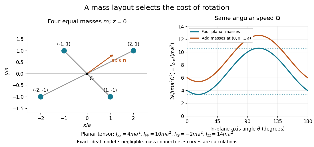
Paired point masses and direction-dependent rotational kinetic energy
. Original exact model. Four equal point masses lie in the plane with negligible-mass connectors. The curves use angular velocity and plot . Adding two more equal point masses at raises this curve by two. Markers depict ideal point masses, not finite-sized weights; no experimental data are plotted. Details.For an in-plane unit vector , the planar model hasIts extrema are the principal moments of inertia and ; the remaining principal moment of inertia is . These values follow from the two-by-two characteristic polynomial , so they can be checked without trusting a numerical eigenvalue routine. At a stipulated angular speed , with and , rotation about , or has rotational kinetic energy , or , respectively.
A truly three-dimensional example adds two more equal point masses at and . Each contributes to the inertia tensor, givingThe in-plane principal axes stay the same while their principal moments of inertia each increase by . The moment of inertia stays unchanged because the added point masses lie on that axis. This comparison changes the total mass from to ; it holds the original four point masses fixed rather than redistributing a fixed total mass.
PASCO's PASPORT Rotary Motion Sensor Experiment Guide, Experiment 1, specifies a PS-2120A sensor, a rod carrying two equal-radius weights, a three-step drive wheel, a thread and hanging mass, a clamp-on guide wheel, a support, a balance and calipers. The thread leaves the drive wheel tangentially. The sensor records angular velocity against time; a linear regression over the accelerating interval supplies angular acceleration . The guide measures the drive radius with calipers and repeats the run with the weights removed to subtract the apparatus's own moment of inertia. Its tables are blank: it prescribes a measurement and does not report an observed numerical agreement. [ref]
With hanging mass including its hanger, effective drive radius , no thread slip and negligible guide-wheel inertia, Newton's second law gives thread tension . The axial torque is . Under negligible friction, the inference is thereforeRepeat the inference for the unloaded assembly and subtract: . Omitting the term incorrectly treats thread tension as the hanging weight. Comparing with tests the point mass approximation; finite-sized weights also have their own moments of inertia about their centres of mass. [ref]
Useful proposed checks go beyond that ideal inference. Verify the rotary encoder's angle scale by turning the shaft through a marked full revolution; check the recorded time against an independent clock and the balance against a known mass. Measure at the thread's running surface, including thread thickness; avoid overlapping wraps that change . Release without a push, inspect the angular velocity record for a straight interval, and stop before the hanger lands or the thread runs out. Repeat with several hanging masses, weight radii and rotation directions. A consistent inferred moment of inertia across drive torques supports the model; curvature, direction dependence or drift indicates a limitation rather than a new principal moment of inertia.
For approximately constant resisting torque in one rotation direction, an original calibration model isFit the left-hand quantity against across several drives: the slope estimates the axial moment of inertia and the intercept estimates . This calibration is conditional on friction remaining constant over the fitted angular speeds; a freely slowing run can expose speed dependence. Sensor differentiation noise, guide-wheel moment of inertia, thread slip, flexing connectors and uncertain weight radii limit the inference. Removing weights can also change bearing loads, so empty-apparatus subtraction does not automatically cancel friction. These are proposed controls and a model extension, not results claimed by PASCO.
A fixed-axis readout measures , not the full inertia tensor. In a proposed generalization, repeat about , , and the three diagonal directions , , , all through the same . For example,Six independent scalar readings then determine the six entries of a symmetric matrix. Each mounting needs its own apparatus correction, and different reference points require the tensor parallel-axis theorem before the readings can be combined.
A rotary encoder converts shaft rotation into a readout of angle or changes in angle. The PS-2120A uses interruptions of a light beam to encode shaft motion; its product specification gives 4000 divisions per revolution. That count is a resolution specification, not a guarantee of the precision of an inferred angular acceleration or moment of inertia. [ref]
If is the center of mass and , expanding the defining inertia tensor about gives the displayed formula. The cross terms vanish because in coordinates centred at . Contracting with a unit axis gives the parallel axis theorem, with the squared distance between the parallel axes equal to .
The principal moments of inertia about a specified point are the eigenvalues of the inertia tensor . Their associated unit vectors that are eigenvectors specify principal axes through . The spectral theorem for real symmetric matrices guarantees an orthonormal basis of these eigenvectors, even for an irregular rigid body. Choose their signs to make a right-handed basis and collect them as the columns of an orthogonal matrix :Thus diagonalization removes the off-diagonal coupling in the rotational kinetic energy. The eigenvalues belong to the mass distribution and reference point, independently of which orthonormal basis initially describes them. [ref]
In this principal body frame, write angular velocity as . ThenUse these as total angular momentum and kinetic energy only under the reference-point conditions stated under inertia tensor. Along a single principal axis with , angular momentum is parallel to angular velocity. For a mixture of directions with different principal moments of inertia, it generally is not. A principal axis need not be a geometric symmetry axis: it is selected by the complete mass distribution. A principal axis also need not give stable free rotation; for three distinct principal moments of inertia, the intermediate axis theorem supplies the stability distinction.
For any unit vector ,The axial moment of inertia is a weighted average of the principal moments of inertia. At fixed angular speed, the least and greatest rotational kinetic energies occur in the corresponding eigenspaces. At fixed nonzero angular momentum magnitude , instead, , so the largest principal moment of inertia gives the smallest rotational kinetic energy. These comparisons hold the reference point fixed.
There is an additional physical restriction beyond positive semidefiniteness. In principal axes coordinates,with two analogous cyclic inequalities. Therefore three arbitrary positive numbers do not always represent a possible inertia tensor. For a distribution in the plane through , , as in the planar inertia tensor of paired point masses. A uniform solid ellipsoid of mass and semiaxes supplies a continuous three-dimensional example: using its mass second-moment tensor, its central principal moments of inertia are , , . Setting recovers the moment of inertia of a uniform solid sphere.
For strictly positive principal moments of inertia and a fixed rotational kinetic energy , the allowed angular velocity components form an ellipsoid:Its semiaxis lengths have units of angular speed. The longest semiaxis corresponds to the smallest principal moment of inertia: that direction permits the greatest angular speed for the same rotational kinetic energy. This is a surface in angular velocity space, not the physical outline of the body. If one principal moment of inertia vanishes in an ideal line-mass model, this constant-energy surface is unbounded in that direction and is no longer an ellipsoid.
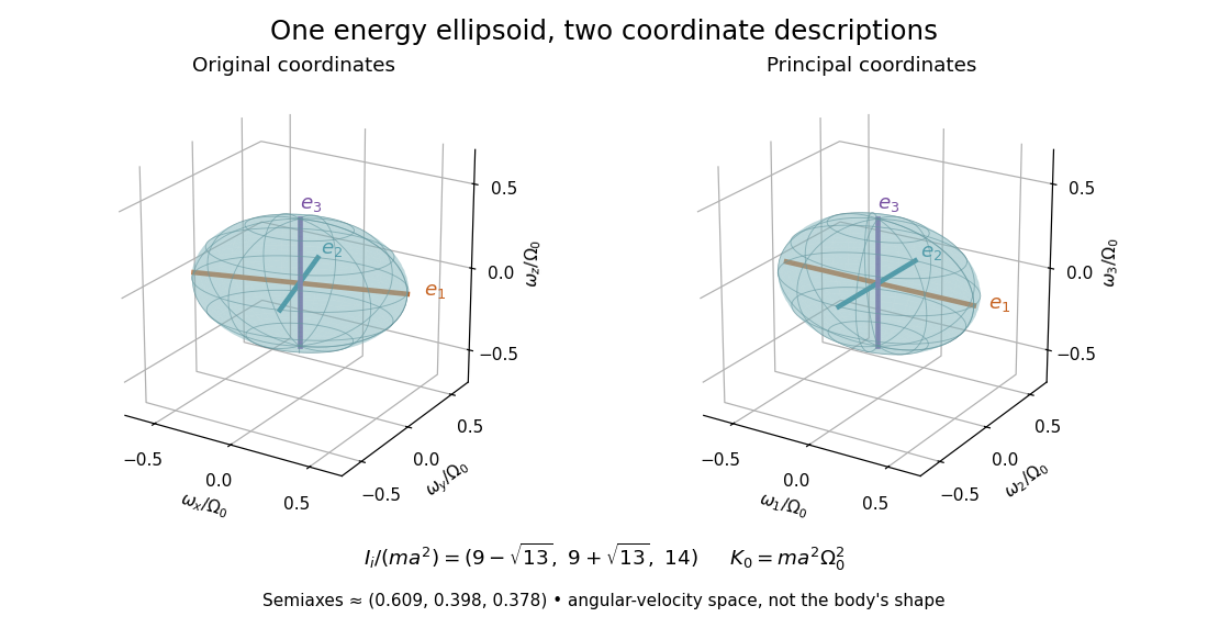
The rotational energy ellipsoid gives the geometry behind Poinsot's ellipsoid, but a constant-energy surface alone does not determine a free-rotation trajectory. A torque-free trajectory must also satisfy the conserved angular momentum constraint and the Euler equations for a torque-free rigid body.
If two principal moments of inertia coincide, for example , every direction in their two-dimensional eigenspace is a principal axis. The perpendicular axis is determined, but there is no privileged orthogonal pair within that plane. Rotating the pair in the plane leaves the diagonal inertia tensor unchanged. If all three principal moments of inertia coincide, and every axis through is principal. This follows from the eigenvalue multiplicity and eigenspace, rather than from a failure of diagonalization. [ref]
Equal principal moments of inertia do not prove that a body's outline has continuous rotational symmetry. For example, six equal point masses at , and have . This discrete layout has the same axial moment of inertia in every direction, although its actual mass distribution changes under most rotations. Conversely, even when all three principal moments of inertia are distinct, principal axes are unoriented lines: reversing an eigenvector's sign gives the same axis. Near repeated eigenvalues, small measurement errors can rotate fitted principal axes substantially within the nearly degenerate eigenspace, so quoted directions need an uncertainty assessment as well as quoted principal moments of inertia.
For torque-free rigid-body motion, the kinetic-energy ellipsoid fixed in the body rolls without slipping on the invariable plane perpendicular to the conserved angular momentum. Its point of contact is the angular-velocity vector.
The herpolhode is the contact curve traced on the fixed invariable plane in Poinsot's torque-free construction. It is distinct from the polhode, which is described in body coordinates.
The polhode is the contact curve traced on the body's energy ellipsoid during Poinsot's torque-free rolling construction.
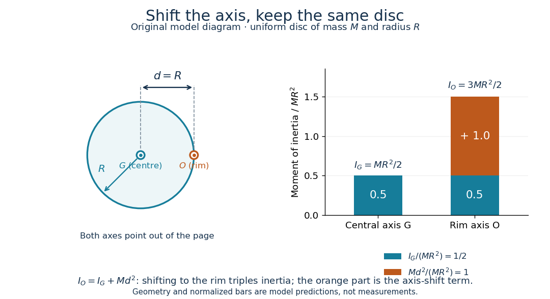
The parallel axis theorem transfers a moment of inertia from an axis through the centre of mass to a parallel axis through :Here is the total mass and is the shortest perpendicular distance between the two axes. Both moments of inertia concern the same mass distribution and the same axis direction. The axis for must pass through the centre of mass; may refer to an axis outside the body. No uniform-density or planar-shape assumption is needed. Within any family of parallel axes, the centre of mass axis minimizes the moment of inertia.[ref]
A short proof isolates why the centre of mass matters. Choose parallel axes perpendicular to an plane, put at the origin, and place at . Thenbecause in centre of mass coordinates. Individual mass elements can move closer to the new axis, but their weighted cross terms cancel. For arbitrary parallel axes and , use , where each distance is measured from the parallel centre of mass axis; adding times the squared separation of and is generally incorrect. A displacement along the axis has . Changing the axis direction instead requires the inertia tensor or, in its applicable planar setting, the perpendicular axis theorem.
For a uniform disc, mass and radius , the central perpendicular moment of inertia is . Shifting that axis to the rim gives and , three times . In the computed , example, , and . At angular speed the rim-pivoted disc has rotational kinetic energy . Its centre of mass now moves, so already includes that translation; adding a separate centre of mass translation term to it would count that contribution twice.
The physical pendulum measurement described under moment of inertia provides a practical check: infer at several pivot positions, then subtract to obtain . Keep all pivot axes parallel and measure to the centre of mass of the entire moving assembly. The same assembly should yield the same within measurement precision. If a smartphone is attached, its mass and its own moment of inertia belong in both the geometric prediction and the centre of mass calculation. The published bar-and-phone study explicitly adds both contributions using the parallel axis theorem.[ref]
For a careful replication, release small swings without a push, repeat timings at several small amplitudes, and check that the extrapolated oscillation period is stable as amplitude decreases. Time many complete oscillations and repeat the run; two crossings of a photogate per cycle must not be mistaken for two cycles. Inspect decay of amplitude and compare early and late timings to detect significant pivot friction or air drag. Mark the bar and phone mount to detect relative slip, tighten the attachment, and check that the pivot support does not rock or migrate between holes. Repeat with an independent photogate or video readout to check the phone's timing. These are proposed controls for the replication, not additional results reported by the authors. The ideal model excludes appreciable damping, large swings and flexing; subtraction of also magnifies relative errors when is much smaller than .
The oscillation period need not increase monotonically with pivot distance: the shift raises the moment of inertia but also increases the gravitational restoring torque. For a computed slender uniform bar model of length , andThis expression has its minimum at . With , and stipulated , the prediction is ; it is not a recorded timing or a prediction for the bar with a phone attached. The competing terms explain why a timing experiment can reveal a mass distribution rather than merely its weight.
For uniform density between concentric radii , subtract the missing solid core's central moment of inertia and then shift the axis by . Here . The thin-shell limit gives , while a full solid sphere gives .
For a planar lamina in the -plane, the moments about three mutually perpendicular axes through one point satisfyThis follows pointwise from in the defining mass integrals.
For an axisymmetric planar lamina of total mass , let be its moment of inertia about the central axis normal to its plane. The perpendicular axis theorem and rotational symmetry give about central diameters. An in-plane tangent line a perpendicular distance from a parallel central diameter therefore has moment of inertia by the parallel axis theorem. An axis normal to the lamina through the same rim point instead has ; specifying the point without the axis direction is insufficient.
For a uniformly filled, negligibly light disc of fixed radius , remaining mass , angular velocity , and tangential exhaust speed relative to its rim, angular-momentum balance givesAt zero relative exhaust speed, is constant.
Articles were limited to the first 100 out of 137 total.
Articles by others on the same topic




Rigid body dynamics is a branch of mechanics that deals with the motion and equilibrium of rigid bodies, which are objects that do not deform under the application of forces. In this context, a "rigid body" is an idealization where the distance between any two points in the body remains constant regardless of the forces applied to it.