The original cover dates this paper to 20 June 2014. The solutions follow the printed numbering and use the supplied natural deduction rules, including double-negation elimination. In the proof tables, the context column lists the numbered assumptions still in force; temporary assumptions are explicitly discharged by the indicated rule.[ref]
Digital systems, linear algebra, introduction to formal proof examination paper by the University of Oxford (2014). Cover and Figures 1–3, printed pages 1 and 9
A MIPS R-type instruction has the 32-bit instruction encodingFor
add $x,$y,$z, the processor register indices are , and , while . The main opcode selects the R-type family and the function field selects addition. The register file reads its two operands from instruction bits 25:21 and 20:16. In the original datapath, RegDst=1 selects bits 15:11 as the destination, ALUSrc=0 selects the second register file output, and ALUFunc=ADD makes the arithmetic logic unit add its inputs. The result returns to wdata; RegWrite=1 writes it to at the active clock edge. The zero output is irrelevant here.[ref]Digital systems, linear algebra, introduction to formal proof examination paper by the University of Oxford (2014). Question 1 datapath, printed page 2: the input-0 and input-1 multiplexer labels determine these control polarities
A MIPS I-type instruction instead has the instruction encodingFor
addi $x,$y,n, , , and the low sixteen bits contain the immediate operand. The register file supplies to the first arithmetic logic unit input. Set RegDst=0 to select bits 20:16 for the destination, and ALUSrc=1 to select the extended immediate operand for the second input. The opcode directly requests addition, so ALUFunc=ADD and RegWrite=1. The second register file read is unused. The returned result is written into .The sign extension circuit retains the low sixteen bits and copies bit 15 into all sixteen new high positions:Thus sign extension preserves the signed two's complement value:
0x7fff becomes 0x00007fff, whereas 0x8000 becomes 0xffff8000. For both instructions, the architectural result above assumes no signed overflow; the full MIPS architecture specifies an overflow exception, which is outside this simplified datapath.Add zero extension alongside sign extension, and a multiplexer controlled by a new signal
ExtSign to select between them before the existing immediate-input connection. Equivalently, make the extender itself selectable:Decode ori to ExtSign=0, RegDst=0, ALUSrc=1, RegWrite=1 and ALUFunc=OR. The arithmetic logic unit then performs bitwise OR between and the zero-extended immediate operand and writes the result to . Extend the arithmetic logic unit's control decoding if OR was not already available. Decode addi to ExtSign=1; the new signal is irrelevant for MIPS R-type instructions because ALUSrc=0.Zero extension matters even when the most significant immediate bit is one:
ori with 0x8000 must only affect the low half of the destination, whereas sign extension would incorrectly force every high bit to one.[ref]MIPS32 Architecture For Programmers Volume II by MIPS Technologies. ORI instruction entry: the 16-bit immediate is zero-extended before the logical operation
Use byte addresses, so adjacent 32-bit array elements are four bytes apart. The following MIPS instructions include harmless
sll $zero,$zero,0 instructions in every branch delay slot; the second load is followed by another independent instruction before its value is consumed, also accommodating an early MIPS architecture with a load-use delay. All mnemonics here denote individual machine instructions. beq $t3,$zero,done # n=0: do not access any array
sll $zero,$zero,0
loop:
lw $t4,0($t0) # current a element
lw $t5,0($t1) # current b element
addiu $t0,$t0,4 # advance a; also separates lw from its use
subu $t6,$t4,$t5 # current difference, modulo 2^32
sw $t6,0($t2) # store current c element
addiu $t1,$t1,4
addiu $t2,$t2,4
addiu $t3,$t3,-1 # one fewer element remains
bne $t3,$zero,loop
sll $zero,$zero,0
done:A loop invariant at the head of the loop, after completed iterations, is that the three addresses point to elements , the count is , and every output element before equals the corresponding difference. One iteration reads element , stores its difference and advances to , preserving the loop invariant. The remaining count is a nonnegative loop variant decreasing by one, so the loop ends with .
The code uses
subu to avoid signed-overflow traps: the suffix does not restrict the operands to unsigned values. Its precise result isFor representable signed differences this is exactly . If trapping signed arithmetic is required instead, use sub and assume all differences are representable. The arrays must occupy valid word-aligned storage with no address wrap; the usual separate output array avoids overwriting unread inputs.Make the code a leaf procedure called
array_diff, copy the four argument processor registers into the temporaries used above, and replace the final label by a return. The copies are real addu instructions, avoiding an unexplained move pseudo-instruction:array_diff:
addu $t0,$a0,$zero
addu $t1,$a1,$zero
addu $t2,$a2,$zero
addu $t3,$a3,$zero
# insert the code of (i), including its initial zero-count test
# use the local label array_diff_done in place of done
array_diff_done:
jr $ra
sll $zero,$zero,0In the literal insertion, the
done: line from (i) is the array_diff_done: line displayed here; it is not a second return block. Under the usual calling convention, temporary processor registers are caller-saved. This procedure calls no other procedure and changes no saved processor registers, so it needs no stack frame or saved return address.For a 32-bit constant , define and using its unsigned binary representation. Load it with
lui followed by ori; both are single MIPS instructions. For base addresses and count , the main program is:main:
lui $a0,H_A
ori $a0,$a0,L_A
lui $a1,H_B
ori $a1,$a1,L_B
lui $a2,H_C
ori $a2,$a2,L_C
lui $a3,H_N
ori $a3,$a3,L_N
jal array_diff
sll $zero,$zero,0
main_after_call:
# c now contains the differences; continue the main program hereHere each
H_... and L_... is an assembler-time numeric constant, not an executed operation. lui places the high half and clears the low half; ori inserts the low half without sign extension. ThusThe jal instruction saves the return address after its branch delay slot in $ra; jr $ra resumes at main_after_call. A main routine that itself needs to return to a caller must save its incoming $ra before jal and restore it afterwards.Names live in directory entries. Each ordinary directory entry associates a component name with an inode number; the corresponding inode describes the file and locates its contents. A name is therefore not stored as the identity of the inode, and hard links can give one inode several names.
To resolve
/var/mail/user, start from the root file-system directory's inode, read its directory entries and find var. Follow that entry's inode number to the var inode; read that file-system directory and find mail; repeat for user. The final inode supplies the file metadata and addresses needed to read the file data blocks. The intermediate file-system directories require search permission. This describes ordinary pathname traversal without a symbolic link or mount point changing the route.An inode holds file metadata: object type, owner and group identities, access permissions, file size, access/modification/status-change timestamps, and the hard link count. It also holds the information locating the contents, traditionally direct addresses and indirect block pointers. Device-special files instead need device-identifying information. The file's name and parent pathname belong to directory entries, not to the ordinary inode.
A traditional inode uses a fixed number of direct pointers to file data blocks, followed by singly, doubly and sometimes triply indirect block pointers. A singly indirect block pointer reaches one address block whose entries point to file data blocks. A doubly indirect block pointer reaches a block of pointers to singly indirect address blocks; a triply indirect one adds another level. The file data blocks need not be physically contiguous.
This multilevel inode indexing keeps the inode compact. A small file uses direct pointers without allocating address blocks, while a large file allocates deeper address blocks only as needed. If each address block holds addresses, the successive levels cover file data blocks. The logical file offset selects a path arithmetically, so random access does not require walking through all preceding file data blocks.
An access control list is attached to an object, such as a file, and lists which subjects or groups may perform which operations. Access requires checking the requesting identity against that object's list. A security capability is an unforgeable reference to an object carrying specified rights; possessing valid authority is what permits access. Protected storage or another integrity mechanism must prevent users manufacturing stronger security capabilities.
The traditional Unix owner/group/other read-write-execute permissions are a compact, restricted access control list: the inode records the owner, group and permission bits, and the operating system compares these against the caller's credentials.An already-open file descriptor can behave like a limited handle carrying rights, but that does not change the identity-based nature of the initial pathname permission check.
Each address uses bytes, so an address block holds pointers. Use zero-based file offsets. The requested file offset hasThus select direct pointer index 1, read its file data block, and take the byte at offset 952 within it. No address block is needed:Fetching an uncached inode adds one read. If “byte 3000” instead uses one-based numbering, the within-block offset is 951; it is still the second file data block, with the same read count. Pathname lookup is separate from accessing a known inode.
The logical file data block index and within-block file offset areDirect pointers cover logical indices 0 through 9. The singly indirect region covers 10 through . The requested file data block therefore lies in the doubly indirect region, at relative indexFollow the doubly indirect block pointer in the inode, read its top address block and select entry 14, read that second address block and select entry 511, then read the resulting file data block and take byte offset 1568. These entry indices are zero-based.This assumes a resident inode and no useful buffer cache entries for the three blocks; an uncached inode adds one read. Under one-based byte numbering the last offset is 1567, without changing either address-block index or the read count.
With a resident inode, the deepest allowed path uses two address blocks and one file data block, so every byte through the end of the doubly indirect region meets the three-read bound. There are ten directly addressed file data blocks, 512 singly addressed ones and doubly addressed ones. Therefore the largest contiguous file satisfying this bound isThe next byte requires the triply indirect region, with three address-block reads and a fourth read for the file data block.
The resident-inode convention is essential. If the question's three reads must also include fetching a previously uncached inode, only two further reads remain; the maximum is thenNeither figure includes arbitrary pathname-resolution reads. These are worst-case counts in the traditional fully allocated multilevel inode indexing model; existing buffer cache entries can reduce them.
Use three D flip-flops whose stored bits represent . Initialize them to . The Moore machine's output is this stored binary representation, and its state transition table is:
| Present | Next |
|---|---|
Treat the two unused state encodings as don't-care conditions when minimizing the sum of products. With juxtaposition for AND, for OR and a bar for NOT, one minimal choice isFor , the required ones at and cannot share one valid implicant: their differing bits would force inclusion of required zeros. Pair with the unused to get , and with unused to get . Neither term can lose a Boolean literal without covering a required zero.
For , state is isolated from every other required one and from the unused states by required zeros, so it forces the three-Boolean literal term . State pairs with unused to give . Finally is a single Boolean literal. Thus the three expressions are minimal sum of products expressions under the stated unused-state convention. In fact these choices also recover from , so initialization into an unused state eventually joins the intended modulo-six counter cycle.
Let the stored bits be , with most significant. The required Gray code transitions giveConnect directly to the first D flip-flop's data input and feed through one NOT gate to the second input. Drive both enable inputs with and both clock inputs with the same clock. Thus holds both stored bits; takes the next Gray-code counter state at the active clock edge. Reset initializes .
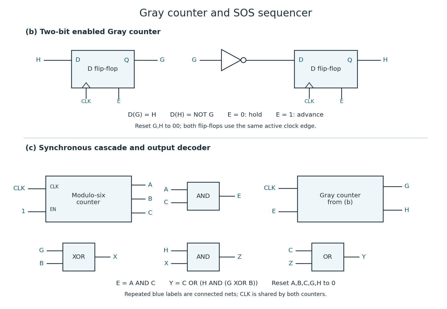

With ordinary uncomplemented outputs, one NOT gate is minimal: wiring alone cannot produce . If a D flip-flop already provides a complementary output, that output supplies the inversion without an external logic gate. This is a Moore machine because its output depends only on stored state; controls transitions.
Use a synchronous counter cascade, with the three-bit modulo-six counter advancing on every active clock edge and the Gray-code counter advancing only when the old binary state is . Its enable can therefore beOn the six valid binary states, only at . Both digital counters sample the same clock: at an edge leaving , the binary output becomes and simultaneously advances to the next Gray code. At all other edges holds. Starting from , this gives exactly the listed 24-state sequence. Use the shared clock and an enable, rather than making a combinational terminal-state signal into a new clock.[ref]
Digital systems, linear algebra, introduction to formal proof examination paper by the University of Oxford (2014). Question 3(c), printed page 4: original 24-row state/output table
For the output , every state with has . For , the only extra high states are with binary state , and with binary state or . On valid states these conditions are and , respectively. HenceThe lower circuit in the figure implements this with an AND for , an exclusive or on , an AND with , and an OR with . The resulting Morse code output blocks, in Gray code order , areAcross the two middle blocks these join to three three-clock highs separated by one-clock lows; the first and last blocks provide the three single-clock highs of each S. The specified table is a repeating SOS symbol pattern; its wraparound has a one-clock low, rather than an added inter-message pause. The output is a Moore machine decoding of current stored bits; its value changes after those bits settle.
Apply the elementary row operations from bottom to top: , , and . This order ensures that each subtraction uses the original preceding row. The result is the upper triangular matrixPut , , , . Row is either zero if , or has its first nonzero entry in column . Thus, for arbitrary real parameters, a row echelon form is obtained by retaining the nonzero rows of in their existing order and moving every zero row to the bottom. This deals explicitly with vanishing parameters; an upper triangular matrix with an intermediate zero row is not yet a row echelon form.
The subtractions preserve the determinant, so the original matrix hasA square matrix is invertible exactly when its determinant is nonzero. Consequently,These conditions concern consecutive parameters: no ordering, positivity, or pairwise distinctness of all four is required. More generally the rank of a matrix here is the number of nonzero , because the retained nonzero rows have distinct leading columns.
Summing the flow conservation equations over all four junctions cancels every internal flow. The total entering flow is , and the known exiting flow is . ThusThe original arrows point , , , and for , respectively. In particular, exits north from .[ref]
Digital systems, linear algebra, introduction to formal proof examination paper by the University of Oxford (2014). Question 4(b) traffic diagram, printed page 5
The individual flow conservation equations areChoose . Substitution gives all solutions of these linear equations:The inequalities enforce nonnegative flows on all one-way streets. The last junction equation follows from the first three and total flow conservation, so it introduces no further restriction.
The maximum is . It makes . At , all 300 vehicles arriving from the west turn north and leave along ; none arrives from or continues east to .
For a real matrix , the row space is the linear span of its rows in , and the column space is the linear span of its columns in . Its null space consists of the input vectors sent to zero:The rank of a matrix isThe equality of row and column dimensions is the row-rank/column-rank theorem. Each displayed space is a linear subspace of the indicated ambient vector space.
Write the columns of as and the coordinates of the vector as . By the definition of matrix multiplication,Indeed, its th coordinate is , exactly the th coordinate of this linear combination. Since the column space contains every linear combination of the columns, the claim holds for every vector .
Swap the first two rows, then perform and . These elementary row operations giveScale row 2 by , subtract it from row 3, and finally subtract twice row 2 from row 1. The reduced row echelon form isElementary row operations preserve the row space. The two nonzero rows of are linearly independent, since their leading entries lie in different columns. Hence
The pivot columns of the reduced row echelon form are columns 1 and 3. Take those columns of the original matrix, since elementary row operations need not preserve the original column space:For an explicit spanning check, column 2 is , column 4 is , and column 5 is . The first two coordinates of the displayed columns form a matrix of determinant , proving their linear independence. They are therefore a basis of the column space.
The right-hand vector is in the column space, becauseConsequently the linear system is consistent. A concrete solution isAs a compatibility check, the original rows satisfy , and the right-hand entries satisfy the same relation . There are infinitely many solutions, obtained by adding any vector in the null space to the displayed solution.
The reduced row echelon form yieldsTake the free variables in a linear system to be , , . ThenThusEach listed vector lies in the null space, and every solution has the displayed form. Their coordinates in positions 2, 4 and 5 prove linear independence. The dimension also follows from the rank-nullity theorem: .
An elementary matrix acts on rows by multiplication on the left. Apply the desired elementary row operation to the identity matrix to construct it. In the order requested, the three elementary matrices and their inverse matrices areThe inverse operations halve row 1, add twice row 1 to row 3, and interchange rows 2 and 3 again, respectively.
Use and , followed by . These elementary row operations giveThe elimination multipliers are , , . Record them in the unit lower triangular matrix :To see the elementary matrix relation directly, let , and , where has a single 1 in position . Then , and reversing and inverting these operations gives . Direct matrix multiplication also verifies the stated LU decomposition.
Solve two triangular linear systems, rather than forming an inverse matrix:For this LU decomposition, forward substitution gives , and . Then back substitution givesAll diagonal entries used as divisors are nonzero. The same LU decomposition can be reused for many right-hand vectors, with only these two triangular solves repeated.
A triangular matrix has determinant equal to the product of its diagonal entries. Since is a unit lower triangular matrix, . ThusEquivalently, the elimination used only row additions, which leave the determinant unchanged; there were no row swaps or row scalings to account for.
The conjunction introduction rule derives from proofs of and in the current context. The disjunction elimination rule derives a common conclusion from , a subproof of under temporary assumption , and a subproof of under temporary assumption . The implication introduction rule derives by temporarily assuming and proving .
The rectangular boxes delimit subproofs and the scope of their temporary assumptions. The disjunction elimination rule discharges the two case assumptions; the implication introduction rule discharges its antecedent assumption. Formulas depending on a boxed assumption cannot simply escape that box. Other undischarged assumptions remain in force, and nested boxes can access the assumptions of enclosing boxes.
Work backwards from the outermost available logical connective. One strategy applies the disjunction elimination rule to the premise first, constructs the whole target in each case, and then closes the cases. In the tables, a context such as means that assumptions on lines 1 and 2 remain open. A range in a discharge rule denotes the entire local subproof.
| Line | Context | Formula | Justification |
|---|---|---|---|
| 1 | Premise | ||
| 2 | Temporary assumption | ||
| 3 | conjunction elimination rule on 2 | ||
| 4 | conjunction elimination rule on 2 | ||
| 5 | disjunction introduction rule on 4 | ||
| 6 | conjunction introduction rule on 3, 5 | ||
| 7 | Temporary assumption | ||
| 8 | conjunction elimination rule on 7 | ||
| 9 | conjunction elimination rule on 7 | ||
| 10 | disjunction introduction rule on 9 | ||
| 11 | conjunction introduction rule on 8, 10 | ||
| 12 | disjunction elimination rule on 1, 6, 11; discharge 2, 7 |
A second strategy applies the conjunction introduction rule backwards to the target first. Prove and separately, each by the disjunction elimination rule on the premise, and combine them:
| Line | Context | Formula | Justification |
|---|---|---|---|
| 1 | Premise | ||
| 2 | Temporary assumption | ||
| 3 | conjunction elimination rule on 2 | ||
| 4 | Temporary assumption | ||
| 5 | conjunction elimination rule on 4 | ||
| 6 | disjunction elimination rule on 1, 3, 5; discharge 2, 4 | ||
| 7 | Temporary assumption | ||
| 8 | conjunction elimination rule on 7 | ||
| 9 | disjunction introduction rule on 8 | ||
| 10 | Temporary assumption | ||
| 11 | conjunction elimination rule on 10 | ||
| 12 | disjunction introduction rule on 11 | ||
| 13 | disjunction elimination rule on 1, 9, 12; discharge 7, 10 | ||
| 14 | conjunction introduction rule on 6, 13 |
Both derivations establishCounting only applications of inference rules, each proof has nine steps: four conjunction elimination rule applications, two disjunction introduction rule applications, and three remaining applications. The first uses two conjunction introduction rule applications and one disjunction elimination rule; the second uses one and two, respectively. The second has two additional temporary-assumption lines, giving 14 displayed lines instead of 12, but assumptions are not additional inference applications. Its duplicated case analysis is exchanged for avoiding construction of the complete logical conjunction separately in both cases. In a proof tree it also repeats the use of the original premise.
Introduce the three logical implications from the outside in. Under assumptions , , and , apply the implication elimination rule twice, then use assumption discharge in reverse order:
| Line | Context | Formula | Justification |
|---|---|---|---|
| 1 | Temporary assumption | ||
| 2 | Temporary assumption | ||
| 3 | Temporary assumption | ||
| 4 | implication elimination rule on 1, 3 | ||
| 5 | implication elimination rule on 2, 4 | ||
| 6 | implication introduction rule on 5; discharge 3 | ||
| 7 | implication introduction rule on 6; discharge 2 | ||
| 8 | implication introduction rule on 7; discharge 1 |
Thus
Under , the first assumption yields , while the second yields . Apply the implication elimination rule once more to obtain , and discharge the three temporary assumptions:
| Line | Context | Formula | Justification |
|---|---|---|---|
| 1 | Temporary assumption | ||
| 2 | Temporary assumption | ||
| 3 | Temporary assumption | ||
| 4 | implication elimination rule on 1, 3 | ||
| 5 | implication elimination rule on 2, 3 | ||
| 6 | implication elimination rule on 4, 5 | ||
| 7 | implication introduction rule on 6; discharge 3 | ||
| 8 | implication introduction rule on 7; discharge 2 | ||
| 9 | implication introduction rule on 8; discharge 1 |
The premise turns an assumed into a contradiction. Use the negation introduction rule to obtain , then the supplied classical double-negation elimination rule:
| Line | Context | Formula | Justification |
|---|---|---|---|
| 1 | Premise | ||
| 2 | Temporary assumption | ||
| 3 | implication elimination rule on 1, 2 | ||
| 4 | negation introduction rule on 3; discharge 2 | ||
| 5 | double-negation elimination on 4 |
Hence . The final classical rule is essential: deriving alone is not yet a proof of in Intuitionistic propositional logic.
Assuming lets the disjunction introduction rule produce the logical disjunction excluded by the premise. This gives a contradiction, so conclude by negation introduction and double-negation elimination:
| Line | Context | Formula | Justification |
|---|---|---|---|
| 1 | Premise | ||
| 2 | Temporary assumption | ||
| 3 | disjunction introduction rule on 2 | ||
| 4 | negation elimination rule on 3, 1 | ||
| 5 | negation introduction rule on 4; discharge 2 | ||
| 6 | double-negation elimination on 5 |
A variable is fresh for the relevant context when it occurs free in none of its undischarged assumptions. For the existential quantifier elimination rule, it must also not occur free in the final conclusion or the existential premise: it is a new eigenvariable, allowed in the temporary witness assumption and formulas inside that witness subproof. Bound variable names can always be renamed to avoid collisions.
The premise guarantees some witness, without saying which object it is. Temporarily call one such witness and assume . If the subproof yields without depending on any special identity or extra property of , its conclusion holds whichever witness exists. The existential quantifier elimination rule therefore discharges and retains only the original existential premise and other open assumptions.This eigenvariable condition prevents inferring for a previously chosen object merely from existence. In particular, does not license outside the discharged witness subproof.
The existential premise is , with the logical implication inside the existential quantifier. Eliminate it using a fresh witness , specialize to that same witness, and introduce the required existential quantifier before closing the witness subproof:
| Line | Context | Formula | Justification |
|---|---|---|---|
| 1 | Premise | ||
| 2 | Premise | ||
| 3 | Temporary assumption | ||
| 4 | universal elimination on 2; instantiate at | ||
| 5 | implication elimination rule on 3, 4 | ||
| 6 | existential quantifier introduction rule on 5; witness | ||
| 7 | existential quantifier elimination rule on 1, 6; discharge 3; fresh |
Extract the universally quantified logical implication and the existentially quantified logical conjunction from the premise. Use one fresh witness for both conjuncts of the latter, so that the resulting and concern the same object:
| Line | Context | Formula | Justification |
|---|---|---|---|
| 1 | Premise | ||
| 2 | conjunction elimination rule on 1 | ||
| 3 | conjunction elimination rule on 1 | ||
| 4 | Temporary assumption | ||
| 5 | conjunction elimination rule on 4 | ||
| 6 | conjunction elimination rule on 4 | ||
| 7 | universal elimination on 2; instantiate at | ||
| 8 | implication elimination rule on 7, 5 | ||
| 9 | conjunction introduction rule on 8, 6 | ||
| 10 | existential quantifier introduction rule on 9; witness | ||
| 11 | existential quantifier elimination rule on 3, 10; discharge 4; fresh |
The witness occurs in no undischarged premise or final conclusion. Therefore the existential quantifier elimination rule is valid and gives
Use the equality introduction rule to prove . In the equality elimination rule, choose the first-order formula to be . Substituting for in its first position proves symmetry:
| Line | Context | Formula | Justification |
|---|---|---|---|
| 1 | Premise | ||
| 2 | equality introduction rule | ||
| 3 | equality elimination rule on 1, 2 |
Thus . This uses only the two supplied equality rules; symmetry has not been assumed as an additional rule.
Eliminate the existential premise with fresh witness . Its first conjunct gives and its second gives . For a fresh arbitrary , one direction of the desired logical biconditional follows by universal elimination. For the other, must be reversed before transporting to using the supplied oriented equality elimination rule.
| Line | Context | Formula | Justification |
|---|---|---|---|
| 1 | Premise | ||
| 2 | Temporary assumption | ||
| 3 | conjunction elimination rule on 2 | ||
| 4 | conjunction elimination rule on 2 | ||
| 5 | universal elimination on 4; instantiate at | ||
| 6 | Temporary assumption | ||
| 7 | equality introduction rule | ||
| 8 | equality elimination rule on 6, 7 | ||
| 9 | equality elimination rule on 8, 3 | ||
| 10 | implication introduction rule on 9; discharge 6 | ||
| 11 | biconditional introduction rule on 5, 10 | ||
| 12 | universal introduction on 11; fresh | ||
| 13 | existential quantifier introduction rule on 12; witness | ||
| 14 | existential quantifier elimination rule on 1, 13; discharge 2; fresh |
Here is absent from every open assumption when line 12 uses universal introduction. In line 13 the existential quantifier binds the witness position occupied by ; the conclusion then has no free , allowing line 14 to close its witness subproof. HenceThe premise says an object satisfying exists and every object satisfying equals it. The logical biconditional adds the converse explicitly: every object equal to that witness also satisfies .
Articles by others on the same topic
There are currently no matching articles.