Wave interference is the reinforcement or cancellation that occurs when overlapping wave amplitudes add by the superposition principle. For two monochromatic waves of the same frequency, mutual optical coherence means that their relative wave phase is stable during the observation. Equal wave phases give constructive interference; a half-cycle phase difference gives the destructive interference intensity minimum. Wave amplitudes add before their squares determine wave intensity. [ref]
https://openstax.org/books/university-physics-volume-3/pages/3-1-youngs-double-slit-interference. Ling, Sanny and Moebs, University Physics Volume 3, §3.1: coherent waves and interference
.Consider two overlapping beams in a homogeneous medium, with the same polarization of an electromagnetic wave and individual local time-averaged light intensities . Their phase difference is measured in radians. In the scalar detection convention, the combined local time-averaged wave intensity isThe last term records wave interference; adding alone misses it. The formula describes irradiance when both fields propagate along the same direction, or when the same detector geometry factor is included in all three intensities. For crossing beams it describes the squared electric field response, proportional to scalar wave intensity; a specified component of the Poynting vector also requires the propagation geometry. The ideal crossing plane waves below make that distinction explicit.
For equal individual light intensities , the cosine half-angle identity givesThe constructive interference intensity is at modulo , and the destructive interference intensity is zero at modulo . At phase quadrature, , it is . With and in the same arbitrary wave intensity unit, the maximum is , the minimum is , and the phase quadrature value is : unequal wave amplitudes cannot cancel completely.
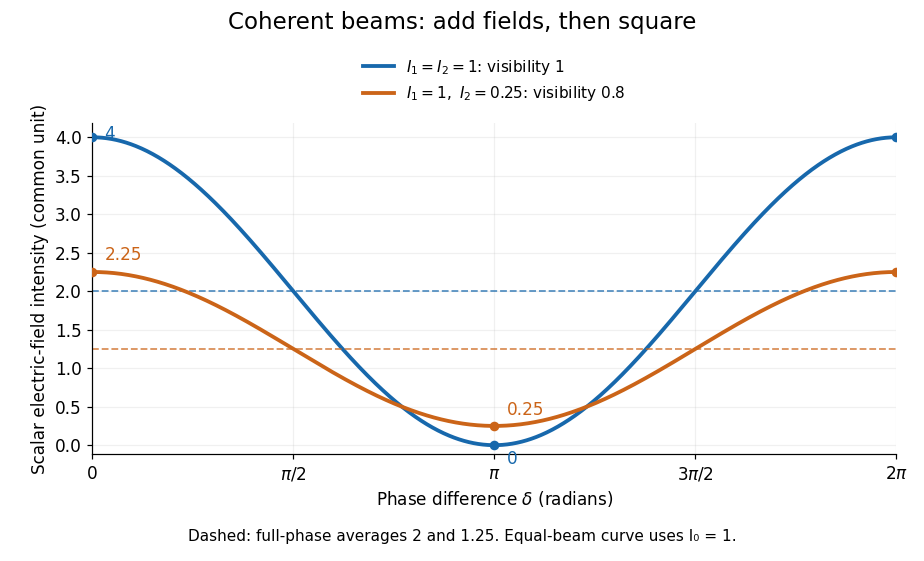
Two-beam wave intensity versus phase difference: equal beams reach 4 and 0; unequal beams reach 2.25 and 0.25
. Details. Both curves use the same wave intensity unit and a horizontal angle in radians. The dashed levels are the averages over a full phase difference cycle. Equal beams have interferometric visibility one; the unequal example has interferometric visibility .
A spatially varying phase difference turns the same law into interference fringes. Take two ideal plane electromagnetic waves with common wavelength , equal individual light intensities , and propagation directions at angles and from the axis in the plane, with . Both have linear polarization along , perpendicular to both propagation directions. Choose equal initial wave phases; their wavevectors and phase difference areHere is the wavenumber and the angular frequency. The common and time terms cancel, so the interference fringes stay at fixed for every . Their interference fringe spacing isSet the length unit to , so that , and take : then . The constructive interference intensity bands lie at integer ; the destructive interference intensity bands lie at half-integer .
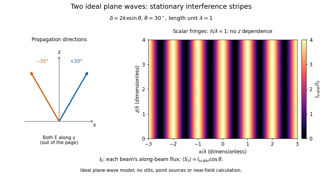


The grid covers and ; both axes are dimensionless lengths in wavelength units. The colour scale is from zero to four, using the same single-beam normalization as the equal-beam curve above. This is an ideal plane wave superposition, with no slits or point sources and no near-field approximation. For these -polarized plane electromagnetic waves in vacuum, the longitudinal time-averaged Poynting vector obeys ; the plotted scalar therefore differs from the irradiance through a plane normal to by that common factor. This relation follows by adding the magnetic fields as well as the electric fields.
The bright peaks do not create energy. Averaging over one interference fringe spacing, or equivalently over one full phase difference cycle, givesbecause the integral of the cosine is zero, with sine as its antiderivative. Equal beams thus average to , despite bright bands at . For the crossing-wave geometry, the average longitudinal energy flux is correspondingly . Bright and dark regions redistribute the incoming energy; conservation of energy concerns the full energy flux, rather than the height of one peak.
Wave interference is useful because phase differences convert small changes in optical path length into measurable changes of wave intensity, as in a Mach-Zehnder interferometer. Its beauty is that the same superposition principle produces both complete cancellation and fourfold brightening; adding more coherent contributions also produces the narrow peaks of a diffraction grating. Feynman's treatment connects this many-source pattern directly to addition of complex amplitudes. [ref].
A short proof outline uses local real fields with parallel linear polarizations. Write and for the same positive conversion factor . Averaging over many wave periods while the phase difference stays fixed uses and , giving the stated law. Equivalently, add the complex amplitudes and take the squared complex modulus. [ref]
https://www.feynmanlectures.caltech.edu/I_29.html#Ch29-S5. Feynman, Leighton and Sands, The Feynman Lectures on Physics, I §29–5: the mathematics of interference
.For different fixed linear polarizations in a common transverse plane, the cross term acquires the dot product of their real unit vectors, equal to for relative angle . Orthogonal linear polarizations remove the cross term in polarization-insensitive scalar detection; different orientations generally only reduce it. A common polarizer can select overlapping components and recover wave interference. Likewise, rapid random variation of the phase difference removes the observed cross term only when the detector's time average has . Slowly varying wave phases can instead move resolved interference fringes, and biased or incompletely sampled wave phases can leave residual contrast. Finite optical coherence therefore depends on the observation time as well as the fields.
Lloyd's mirror produces interference between light arriving directly from a narrow source and light reflected by a plane mirror, which appears to originate at the source's virtual image. With source distance from the mirror, the effective source separation is . A reflection phase shift close to reverses the bright/dark condition relative to two equally phased sources. Spatial filtering, suitable temporal coherence, and direct/reflected beam overlap remain necessary.
Measurement using wave interference: relative path or phase changes are inferred from the resulting signal. The interacting fields must have sufficient optical coherence in the measured modes for the intended interference signal.
Phase unwrapping reconstructs a wave phase field from measurements that determine only its value modulo . If a detector or complex-argument calculation returns , then all values with integers give the same wrapped observation. Recovering a continuous wave phase therefore requires information beyond each isolated value. A primary 1982 analysis discusses this problem in wave phase curves obtained from image Fourier transforms before averaging them.[ref]
Analysis of the phase unwrapping algorithm by Kazuyoshi Itoh. Primary abstract, phase ambiguities and tracking motivation
Define with principal interval . If adjacent true differences satisfy , thenStarting from one reference wave phase, adding these wrapped differences reconstructs the sampled wave phase up to a global multiple of . The proof is direct: wrapping the two endpoint phases changes their difference only by an integer multiple of , and the strict bound selects its unique representative.
For an original example, true phases wrap to . Their wrapped increments are all , so reconstruction succeeds. But true increments produce exactly the same wrapped samples as increments . No algorithm can distinguish those two possibilities from the samples alone without a further assumption. Increasing sampling density can restore the bound only when the field's variation and noise allow it.
In two dimensions, different integration paths introduce a consistency test. A nonzero integer multiple of in the sum of wrapped increments around a closed sampling loop is a phase-unwrapping residue. Noise, undersampling or true wave phase singularities can obstruct a single consistent smooth reconstruction. Choosing an integration path is therefore part of the inference.
For interferometry, low interference visibility can make the wave phase poorly determined even before unwrapping. Unwrapping does not recover information lost where the measured complex amplitude vanishes, nor does it distinguish an actual discontinuity from a smooth but insufficiently sampled change. Report the wave phase reference, principal interval, sampling and any continuity assumptions alongside the reconstructed field.
Phase-shifting interferometry measures an optical phase difference by recording light intensities at controlled relative wave phase shifts. For two sufficiently coherent fields at one detector point, a common model iswhere is a common background, a modulation amplitude and a known applied step. Several measurements separate the unknown wave phase from light intensity background and contrast; a single bright or dark frame generally cannot do so.
A concrete primary implementation was reported in 1974. A piezoelectrically varied reference arm and a 1024-element photodiode array supplied sampled light intensities to a minicomputer, which recovered wave phase by synchronous Fourier-series detection. The paper describes optical-surface and lens testing, repeated sampling and compensation of instrumental wavefront errors.[ref]
Digital Wavefront Measuring Interferometer for Testing Optical Surfaces and Lenses by J. H. Bruning and others. Abstract and p. 2693, apparatus and phase-detection method
This is an experimental implementation of controlled wave phase modulation; it is not a claim that every such system uses the same number of steps.Writing the model asturns wave phase recovery into a linear fit followed by . The step choices must make the three columns independent. Repeating only the same wave phase cannot identify all three unknowns. With more steps, least squares can fit the coefficients while exposing model residuals.
A reflecting reference mirror moved axially by changes its round-trip optical path by in the simple normal-incidence geometry, giving . A quarter-cycle wave phase step thus corresponds to ; at 632.8 nm this is 79.1 nm. These are geometric model values, not a calibration result for the historical apparatus.
Phase-step calibration error, light intensity drift, motion between frames and detector nonlinearity can all break the common-intensity model. The retrieved wave phase remains modulo , so phase unwrapping requires additional spatial or temporal information. The useful observable is the relative wave phase under controlled acquisition conditions, not an absolute optical wave phase inferred from brightness alone.
Four-step phase retrieval estimates relative wave phase from four wave interference frames separated by quarter-cycle wave phase steps. Use the explicit signal-arm conventionwith a common background and modulation amplitude . Opposite-frame differences giveso . The order of the subtractions fixes the sign. Changing which arm receives the wave phase step requires a correspondingly changed convention.
The same data estimate and . A simple model-consistency residual is , which is zero for the exact stated model. It does not detect every possible systematic error.
For an original example, let , and . The four light intensities are , , and . Then , , and the recovered wave phase is . Common background cancels, whereas changing background separately between frames need not cancel.
If independent additive errors in the four light intensities have common variance , first-order propagation givesThis follows from and difference variances . It applies away from vanishing modulation and assumes the specified independent equal-noise model. wave phase uncertainty grows when interference visibility is weak.
The method is a discrete instance of phase-shifting interferometry, whose early digital apparatus used controlled reference-path modulation and synchronous wave phase extraction.[ref]
Digital Wavefront Measuring Interferometer for Testing Optical Surfaces and Lenses by J. H. Bruning and others. Abstract, reference-arm modulation and Fourier-series detection; the four-frame derivation here is separate
The result is still a principal wave phase; phase unwrapping cannot be replaced by choosing a different arctangent branch at each pixel without a consistency rule.Intensity interferometry infers source coherence from correlations between measured intensities, rather than directly combining electric-field amplitudes. For stationary chaotic Gaussian light, the normalized correlations satisfy , under the relevant statistical assumptions.
Separated detectors can therefore measure the magnitude of spatial coherence, which is related to the source's angular structure. Optical carrier phase need not be stabilized as in amplitude interferometry, but fast timing and sufficient photon statistics are crucial. The squared magnitude does not by itself retain every phase needed for unrestricted image reconstruction.
Measurement using interfering light fields. A phase difference changes the detected intensity, allowing measurements of displacement, optical path length or a spectrum. The round-trip phase in a Michelson interferometer gives one explicit path-to-phase calibration; Fourier transform spectroscopy recovers spectral information from an interferogram.
A nearly uniform wavefront phase over one collector is called its piston. Differential atmospheric piston changes the pairwise optical phase without requiring a change in the source. Delay tracking and closure phase address different consequences of this phase error; intensity correlations are unchanged by an ideal pure phase multiplication at either detector.
fringe tracking estimates changing optical delay or phase and adjusts delay compensation to keep an astronomical interferometer near a useful interference condition. The delay must first lie inside the finite-bandwidth coherence envelope; rapid tracking then controls atmospheric piston. This is optical-path stabilization, with sensitivity and reference-source limitations.
A Moiré pattern is a large-scale modulation produced by superposing similar periodic structures. Two identical two-dimensional lattices rotated by a small angle have geometric period in the usual matching geometry. In layered crystals this modulation can act as an electronic superlattice; the actual bands additionally depend on interlayer coupling and orbital structure.
A slow spatial modulation produced by overlapping periodic structures with different projected spatial frequencies or orientations. Its spacing need not equal an atomic lattice spacing.
Subtract the phases and of two projected periodic structures. Their relative phase repeats along the difference vector after distance . For magnitudes and separated by angle , this gives . At zero rotation it reduces to ; equal spacings give . Finite specimen extent limits how many periods can be observed.
Destructive interference occurs when coherent contributions partially or completely cancel their complex amplitudes. For two equal contributions, a phase difference of modulo gives zero resultant wave amplitude. The missing local light intensity is consistent with conservation of energy because the full spatial interference pattern redistributes power.
Thin-film interference combines coherent light contributions reflected or transmitted at the two surfaces of a layer. For a film of refractive index , thickness and internal angle , the round-trip optical path difference is . The relative reflection phase shift must also be included. For a nonabsorbing higher-index film surrounded by air, one of the two leading reflected contributions has a phase shift and the other does not. Reflection maxima therefore satisfy . A smooth reflection spectrum filters many visible wavelengths at once; varying thickness and angle produce spatially varying mixed colours.
A thin liquid layer whose two reflected beams can interfere. For air on both sides, one surface reflection has a phase reversal; a constructive reflected condition is . Thickness and viewing angle therefore alter the selected colours.
With one reflection phase reversal and near-normal incidence, reflected minima satisfy . Subtracting the reciprocal-wavelength conditions for consecutive minima gives the displayed thickness relation. A single maximum between two stated minima identifies the consecutive-order case. Wavelength-dependent refractive index or non-air surroundings can change the inference.
An optical coating designed to reduce reflection through refractive-index choice and thin-film interference. A quarter-wave design is a single-wavelength approximation, not broadband perfection.
A thin-film design that suppresses reflected green light more strongly than red and blue can leave a purple residual reflection. A single quarter-wave layer cancels reflections exactly only at its design wavelength and angle under the ideal index-matching condition. reflection colour should be distinguished from the much smaller colour change of the transmitted beam; multilayer designs can broaden the low-reflectance band.
For a film of refractive index and thickness in air, its round-trip propagation phase is . Two neighbouring same-type interference fringes differ by . At small angular spacing in radians,The relation assumes slowly varying interface reflection coefficients and no rapidly varying reflection phase. At normal incidence the first derivative vanishes, so a local linear angular-spacing formula must be replaced by a quadratic expansion.
A curved transparent surface resting on a plane traps a thin film whose thickness increases radially, producing circular interference fringes. For near-normal reflected light and one relative reflection wave phase change, contact is dark and bright rings obey for . Here is the film's refractive index and the vacuum wavelength. For spherical curvature radius , gives . Consequently for ring diameters . A contact gap, altered reflection phase, or significant oblique incidence changes the formula.
The double-slit experiment compares propagation through two openings. Coherent illumination gives double-slit interference; independent incoherent source patches contribute light intensities whose displaced patterns can reduce the observed interferometric visibility.
Evacuating a transparent cell of optical length in one coherent beam changes its optical path by relative to an unchanged cell in the other beam. With vacuum wavelength , the number of completed fringe periods is . The initial maximum is not an additional completed period. Counting only integer fringes leaves a phase uncertainty of order one fringe unless the final fractional phase is measured; the corresponding index scale is . Fixed equal window contributions cancel in the path difference.
In oblique-incidence two-slit interference, the incident wave contributes a constant phase offset while changing observation angle changes the outgoing optical path difference by . Subtracting the phase conditions of an adjacent minimum and maximum cancels the unknown incidence angle and order and gives the displayed wavelength. Nonadjacent extrema need their intervening phase-order difference; angular spacing should not be replaced by a small-angle formula unless justified.
For two narrow slits separated by , oblique coherent illumination contributes a fixed relative incident wave phase. With a consistent angular convention, the observation-dependent phase is , where is the unknown incidence angle.
The term containing shifts the whole fringe sequence without changing the phase difference between two observed directions. Subtracting the conditions at adjacent bright and dark extrema eliminates this offset and leaves a phase change of . This is the basis of incidence-independent adjacent-fringe wavelength; using the absolute position of one maximum without knowing would confuse source tilt with wavelength or fringe order.
A sequence of individual localized electron detections can accumulate a two-path interference distribution when the apparatus maintains coherence. The 1989 experiment led by Akira Tonomura used a field-emission source, an electron biprism, electron lenses and a position-sensitive electron counter. It realized two coherent paths without literal machined double slits. Low occupation of the instrument excludes interactions between different electrons as the origin of the fringes.[ref]
Double-slit interference depends on the relative wave phase and first-order optical coherence of two collected fields. For equal separately measured intensities, the interferometric visibility is . A small source direction change introduces phase difference for projected interferometric baseline .
Two equally illuminated slits of different widths have field amplitudes . Their interference intensity is . Near the centre, , so the local maximum-to-minimum ratio is . At one slit envelope's zero the interference visibility vanishes even if the other slit still transmits.
The ratio of an envelope width to a fringe period counts spatial intervals. It need not equal the number of bright fringe centres strictly inside the envelope's zeros. For a symmetric overlap from phase index to , the width spans 50 periods, but the strictly interior integer centres are through , totaling 49. Endpoints where one aperture amplitude vanishes have no two-beam contrast. State the count convention rather than treating these as inconsistent answers.
Two equal rectangular apertures of width , centre spacing , and relative phase have Fraunhofer diffraction amplitude proportional to , with and . HenceThe interference zeros satisfy , including the central dark fringe. The single-aperture envelope vanishes at for nonzero integer . A uniform phase reversal translates the narrow-slit fringes by half a fringe without changing their spacing.
Two adjacent half-slits of width h with opposite field transmission have centres separated by h. The aperture transform is . Thus the phase-reversed pair factor multiplies the finite-half-slit envelope, giving the displayed normalized intensity with and . The on-axis field cancels. Positive side maxima satisfy , and total integrated transmission is unchanged by a lossless phase plate even though the angular distribution changes.
A relation between wave phases that lets contributions from successive interaction regions add coherently. In Cherenkov radiation, the condition along the particle trajectory is , relating angular frequency, wave vector and particle velocity.
The daughter photons occupy orthogonal ordinary and extraordinary polarization classes. Alternative assignments to two collected paths can interfere if timing, spectrum and spatial mode do not distinguish them. spatial walk-off and unequal group delays often require compensation.
In a common birefringent down-conversion arrangement, the two daughter photons have the same polarization class, ordinarily both ordinary or both extraordinary relative to the crystal. The pump has a suitable different index for phase matching. This classification alone does not establish polarization entanglement.
Compensation of phase mismatch by a spatial modulation of the coupling coefficient. Write . The driven amplitude contains , so the selected Fourier component accumulates coherently when . For first-order compensation the full spatial period is , twice the nonlinear optical coherence length.
An ideal equal-duty pattern alternating and has first Fourier coefficient of magnitude . Hence its conversion intensity is of a uniformly phase-matched crystal using that same coefficient, under the same undepleted plane-wave assumptions. The modulation can nevertheless allow a larger tensor coefficient or an otherwise inaccessible wavelength. Periodically poled lithium niobate implements such sign reversals using ferroelectric domains.
Periodically poled lithium niobate is lithium niobate whose ferroelectric domain orientation is reversed periodically along an optical interaction path. Reversal changes the sign of the relevant second-order nonlinear optical susceptibility, supplying the spatial modulation needed for quasi-phase-matching.
For a uniform collinear conversion mismatch , a first-order poling period can compensate it through , with signs chosen consistently. The generated contributions then reinforce over many domains instead of repeatedly canceling. The poling period, temperature and input wavelengths determine the useful conversion band; domain defects and finite length affect efficiency. [ref]
https://covesion.com/knowledge-hub/technical-guide-material-properties-of-lithium-niobate/. Covesion manufacturer technical guide: nonlinear coefficients and periodically poled lithium niobate
The residual wave vector difference in a wave-conversion process. For collinear sum-frequency generation, choose . Contributions separated by then differ by wave phase . At phase matching this residual is zero. The sign convention changes some amplitude phases but not the unseeded conversion factor .
The distance over which a constant phase mismatch accumulates phase difference . In unseeded, undepleted sum-frequency generation, the generated intensity first reaches a maximum at this length and returns to zero at . This length concerns relative phases of interacting waves, rather than the temporal optical coherence length of one source.
The slow change in the resultant amplitude when two nearby frequencies interfere. Two steady sinusoidal components at and produce successive amplitude maxima separated by .
A linear time-invariant circuit sends each sinusoidal input to an output at the same frequency, multiplied by its complex transfer function. Two inputs therefore give the sum of two phase-shifted sinusoids. If their output amplitudes are equal, the sum factors into a carrier at the mean frequency and a signed cosine envelope at half the frequency difference. The envelope magnitude repeats at the full difference frequency. Unequal amplitudes give a nonzero minimum; a nonlinear detector is needed to generate a separate difference-frequency signal.
For mutually coherent monochromatic waves with the same polarization of waves in the scalar convention of wave interference, constructive interference reaches its maximum at phase difference , with integer . The wave amplitudes add, giving . Equal individual wave intensities give ; individual wave intensities and give in their common unit. This maximum assumes the optical coherence and detection conditions stated in wave interference.
For the same mutually coherent, equally polarized monochromatic waves, the wave interference minimum occurs at phase difference , with integer . The wave amplitudes subtract, giving . Complete cancellation requires equal individual wave intensities; and leave in their common unit. A dark band is a local minimum, and the average across an interference fringe spacing still obeys conservation of energy.
An interference fringe is a spatial band of enhanced or reduced wave intensity caused by a spatially varying phase difference. Uniform crossing plane waves produce straight parallel interference fringes; curved wavefronts can give curved bands. The interference fringes mark the relative wave phase, rather than the individual instantaneous wavefronts.
A fringe shift measures a change of relative phase between interfering waves in units of a full fringe spacing. A changing optical path difference gives a shift for monochromatic light.
The distance between adjacent bright interference fringes, or between adjacent dark interference fringes, measured along a specified direction. For the symmetric crossing plane waves in wave interference, measured along , . Bright-to-dark separation is . As tends to zero the spacing diverges; at the phase difference is spatially constant and there are no periodic bands.
If the two arms have internal marker states , an interference cross term is multiplied by . Orthogonal markers remove interference from polarization-insensitive detection even if nobody reads the markers. Coherently making the two markers identical erases that distinguishing information and restores the cross term.
// Target: quantum-measurement.bigb
Interferometric visibility measures the contrast of a scanned interference fringe. For the mutually coherent, equally polarized two-beam model in wave interference, with fixed individual wave intensities and , the constructive interference intensity and destructive interference intensity giveEqual nonzero wave intensities give ; give . Unequal wave intensities can therefore reduce interferometric visibility even with perfect mutual optical coherence. Random phase differences or distinguishable wave polarizations can reduce it further; zero contrast alone does not identify the cause. Both intensities zero leave the ratio undefined.
For normalized paths with complex amplitudes and identical internal states, the output probability is , so . A photon polarization fringe alone determines transverse quantum coherence but not the sign of the population difference.
// Target: optics.bigb
Combining equal-intensity beams with complex degree of first-order coherence gives a fringe modulation proportional to . Maximizing and minimizing over observation phase gives visibility . A symmetric source can make real, but it may still be negative. Its sign changes fringe phase by ; it does not represent negative physical contrast.
Articles by others on the same topic
There are currently no matching articles.