Topics (384k) Articles (398k) Users (410) Discussions (242) Comments (383) Files (13k) New article
An output link in an Aho-Corasick automaton points to the nearest terminal state encountered strictly after the current state on its failure link chain. It skips states that do not end a pattern string. After reading a text character, report a pattern at the current state if terminal, then follow output links to report its terminal suffixes.
For dictionary strings
a, ba, aba, reaching state aba reports all three patterns ending at that position. Its output link reaches ba, and the next reaches a. Reporting only aba would miss two valid occurrences. The current state's own match is handled separately because an output link points to a proper suffix, not to itself.If is the failure link destination, the output link is when that state is terminal, and otherwise the output link of . Build this information in increasing trie depth, so the shorter failure states are already available. Traversing only terminal links makes reporting cost proportional to the number of emitted matches, rather than the length of every nonterminal failure chain.[ref]
Efficient String Matching: An Aid to Bibliographic Search by Alfred V. Aho and Margaret J. Corasick. Keyword-matching machine; terminal suffix reporting, with the three-pattern example independently derived
The aerodynamic center is the reference point about which an airfoil's pitching torque is approximately independent of angle of attack over a stated flow regime. More generally the defining test uses the pitching-moment coefficient at fixed flow conditions. The aerodynamic center simplifies replacing a distributed pressure field by an aerodynamic force and a nearly constant residual torque. It differs from the center of pressure, where the resultant's pitching torque is zero and whose position can move as angle of attack changes.[ref]
A thin-airfoil model makes the distinction quantitative. Let be the airfoil chord, a reference area and the dynamic pressure. Define and . Take positive aft from the leading edge and positive pitching torque nose-up. In a chord-line lift model, moving the reference point givesConsequently, when ,Here is angle of attack; differentiating holds the other test conditions fixed. A vanishing lift slope or strongly changing slopes defeats this simple inference.
For an original model choose . Its aerodynamic center is , with . In contrast, setting the pitching torque to zero givesThe center of pressure moves from to as increases from to . With and , the aerodynamic center's residual pitching torque remains while lift doubles. At zero lift the nonzero pure torque cannot be represented by a finite lift application point.
A wind tunnel test can measure lift and pitching torque about a fixed support while stepping angle of attack. The measured slopes determine the inferred aerodynamic center; approximately flat moment data about that point test the model. NASA describes the quarter-chord position as characteristic of most low-speed airfoils. Flow separation, compressibility and three-dimensional wing geometry require their own assessment rather than transferring this location unchanged.[ref]
Aerodynamic interference occurs when nearby bodies alter one another's fluid flow, so their combined aerodynamic loads differ from the sum measured separately under a specified comparison. Pressure fields, boundary layers and fluid wakes can all participate. An aircraft assembly therefore needs an operating-condition definition as well as a list of parts.
A factorial contrast for aerodynamic interference makes that definition measurable. At the same dynamic pressure, model orientation and mounting convention, record a balance reading with component A absent/present according to and component B absent/present according to . The departure from additivity isThe empty-configuration reading matters: it prevents a common support background from being subtracted twice. For original illustrative readings , the interaction is . This aircraft component drag interaction is a property of the stipulated four configurations and conditions.
Kenneth E. Ward's 1931 experiment supplied an early concrete comparison. A Göttingen 387 wing was tested with struts in different upper- and lower-surface positions in a variable-density wind tunnel; separate strut measurements helped distinguish direct strut drag from interaction. Interference could be as large as the struts' own drag.[ref]
Interference Effects and Drag of Struts on a Monoplane Wing by Kenneth E. Ward. Summary, Apparatus and Tests, and Discussion of Results
The contrast does not identify the responsible flow mechanism by itself. Surface pressure measurements and observations of flow separation can test where the changes occur. Comparing at fixed angle of attack also differs from comparing at fixed lift: adding a component can change lift, requiring a new angle or an explicitly documented interpolation for the latter comparison. A negative contrast is possible; interaction can reduce the chosen load as well as increase it.
A pitching moment is a torque about an aircraft pitch axis, associated with rotation of the nose upward or downward. It requires a reference point, an axis and a sign convention; the numerical value is not an intrinsic property of a force alone.[ref]
For a planar chord-line example, take positive aft along the airfoil chord, positive toward the upper surface, and a nose-up moment as positive. An upward chord-normal aerodynamic force applied at has moment about a chord-line reference ,Thus a stipulated upward acting behind the leading edge gives , a nose-down moment. Moving the reference aft to gives without changing the force.
For a distributed aerodynamic load, the same translation law givesDividing by the same yields the reference-point transformation of a pitching moment coefficient. Replacing by lift is an approximation unless the body and flow axes coincide; with a stated angle of attack, the full vector transformation accounts for drag as well.
Net force can vanish while a pitching moment remains. Two stipulated chord-normal forces, at and at , have and . They form a couple; no finite location of a single zero resultant represents that load.
When and a chord-line resultant is meaningful, its center of pressure satisfies . This zero-moment location differs from an aerodynamic center, where moment is approximately insensitive to angle of attack in a specified regime. The latter can have a nonzero moment, especially for a cambered airfoil.[ref]
The lift-to-drag ratio compares the lift supporting an aircraft with the drag opposing its motion. For and , a larger ratio means less drag for a given lift. If both coefficients use the same dynamic pressure and reference wing area , then . Ratios using mismatched reference areas do not have this interpretation.
A parabolic drag polar provides a useful worked model:Here is the zero-lift drag coefficient. In a simple finite-wing model, relates lift-induced drag to wing aspect ratio and a span efficiency factor.[ref]
Induced Drag Coefficient by NASA Glenn Research Center. Induced Drag Coefficient and total drag decomposition
A fitted whole-aircraft can also incorporate additional effects; it need not be determined by geometry alone.The maximum lift-to-drag ratio follows by differentiation:At this point the two modeled contributions to drag coefficient are equal. With the stipulated , and , , and . The optimum is usable only if the actual wing can attain that lift coefficient in the regime where the model is valid; aerodynamic stall can intervene.
For steady unpowered descent in still air, the force balance gives , where is the glide angle. Thus the stipulated optimum corresponds to and about units of horizontal travel per unit of height lost.[ref] Wind and changing flight conditions alter travel over the ground. An airfoil section's ratio also should not be substituted for that of an entire aircraft, which includes other sources of drag.
A drag polar relates drag coefficient to lift coefficient for specified geometry, configuration and flow conditions. It is commonly displayed with horizontally and vertically. The slope of a ray from the origin to a measured point is then , the lift-to-drag ratio when common references are used.
A wind tunnel can obtain a polar by varying angle of attack while recording both forces and the reference dynamic pressure. Reynolds number, Mach number, surface condition and deployed devices must also be recorded; changing one of those can change the curve. A polar is not a geometry-only fingerprint.
For an original illustrative dataset, the pairs lie on . Their positive-lift ratios at and are about and . The larger ratio among those samples does not establish the continuous maximum lift-to-drag ratio; the unsampled neighborhood near performs better in this assumed model.
A parabolic drag polar summarizes such data with a small number of parameters. A shifted parabolic drag polar allows minimum drag to occur at nonzero lift coefficient. Flow separation and changes of flow state can also produce branches or hysteresis that one parabola does not describe. A fit supplies a model whose residuals need inspection, rather than evidence that every unmeasured state lies exactly on the fitted curve.
In the airfoil section plane, the chord-normal aerodynamic force is the component of an aerodynamic force perpendicular to the airfoil chord. The chord-axial aerodynamic force points along the chord, chosen positive aft. These body directions differ from the flow-relative lift and drag axes.[ref]
Aerodynamic Forces by NASA Glenn Research Center. Definitions of Lift and Drag
Choose toward the upper surface and let the incoming flow direction have body components . Resolving the same vector in the two orthonormal bases gives the airfoil force-axis transformation,The rotation matrix preserves the squared Euclidean norm: . An original example with , and gives and . Calling the 100-newton normal reading lift would confuse two different components. The transformation is kinematic; it does not assert that a particular wing produces those loads at that angle.
For a pressure-only reconstruction, the chord-normal component is per unit span when upper and lower surfaces are graphs over the chord. The total can also include viscous stress. A force balance resolving body axes and a pressure reconstruction therefore need matched axes and a stated load decomposition before they are compared.
Lifting-line theory represents a finite aircraft wing by a spanwise bound vortex whose circulation varies with position. The trailing vortex filaments induce downwash, reducing the local effective angle of attack. In its classical form, the model assumes steady, incompressible potential flow, a comparatively large wing aspect ratio, small sweep and locally approximately two-dimensional section behavior.[ref]
Let run along the wingspan, let be the local airfoil chord, and take downward downwash . Combining the Kutta–Joukowski theorem with a linear section law gives
Here is the section lift-curve slope, the zero-lift angle of attack, and the small induced angle of attack. Because the wake induced by the entire circulation distribution determines , these equations couple different sections. Solving independent two-dimensional airfoils and adding their lift misses that coupling.[ref]
Here is the section lift-curve slope, the zero-lift angle of attack, and the small induced angle of attack. Because the wake induced by the entire circulation distribution determines , these equations couple different sections. Solving independent two-dimensional airfoils and adding their lift misses that coupling.[ref]
Prandtl's Lifting Line Introduction (16.100) by MIT OpenCourseWare. pp.2–3, effective angle and fundamental equation
An elliptic span loading has and constant . Integration gives
This is the unit span efficiency factor case.[ref]
This is the unit span efficiency factor case.[ref]
Force Calculations for Lifting Line (16.100) by MIT OpenCourseWare. pp.1–3, lift integral and elliptic loading
For stipulated , , and , it gives , and .A proposed test compares sectional surface pressure integration for airfoil lift with a traverse of the downstream velocity field. The two observations test the predicted loading and wake, rather than only one total force. Flow separation, strong sweep and compressibility require further modeling; the classical calculation does not predict all drag or aerodynamic stall.
The chord-axial aerodynamic force is the component of the net aerodynamic force parallel to an airfoil chord, with positive direction here chosen aft. The perpendicular body component is the chord-normal aerodynamic force . These two components resolve one load vector; flow-relative lift and drag resolve it in a different basis when the angle of attack is nonzero.
Let point aft along the chord, and let point outward from the body. Pressure and viscous stress giveNASA's primary explanation motivates integrating locally normal pressure forces before resolving the resultant into flow axes.[ref]
Aerodynamic Forces by NASA Glenn Research Center. Variation in Pressure and Definitions of Lift and Drag
The explicitly outward normal in this equation fixes the pressure-force minus sign.For a two-dimensional section whose upper and lower surfaces are graphs and , the pressure-only axial load per unit span isThe surface slopes determine how much locally normal pressure projects onto the chord. A pressure force is normal to its local surface, rather than necessarily normal to the chord. Skin friction supplies a further contribution and is not included in .
An original vector example takes N, N and . The airfoil force-axis transformation gives N and N. A forward-directed axial component is therefore compatible with positive drag. It is not, by itself, evidence that the body supplies net propulsive power.
A proposed measurement compares a body-axis balance with integrated surface pressures after matching the angle of attack, sign conventions and support tare. Disagreement can include omitted shear or instrument effects; changing from body axes to flow axes does not remove those physical or measurement contributions.
Reference-area scaling of aerodynamic coefficients changes the numerical coefficients when the normalization area changes, while the physical force stays fixed. For a force component , common dynamic pressure and two choices of aerodynamic reference area,This is an exact change of reporting convention. It makes no assertion about the flow produced by a physically larger model.
For an original example, take Pa, lift 300 N and drag 18 N. With m, the lift coefficient and drag coefficient are 1.00 and 0.060. With m, they become 0.625 and 0.0375. Both describe the same loads, and both give lift-to-drag ratio when the two coefficients use matching references. Mixing the first lift coefficient with the second drag coefficient would instead give a spurious 26.67.
The pitching moment coefficient also contains a reference length:That relation assumes the same dimensional moment about the same reference point. An area change and a reference-point transformation of a pitching moment coefficient are different operations; one rescales a number, while the other changes which moment is being represented.
Matched reference conventions also matter in an airfoil force-axis transformation. A common scalar normalization commutes with the rotation, but coefficients divided by different areas must first be brought to a common scale. The physical force components are obtained from the same integrated surface loading, as the originating NASA technical account explains.[ref]
Aerodynamic Forces by NASA Glenn Research Center. Variation in Pressure; Definitions of Lift and Drag
Retaining area, length, pressure and axis metadata makes comparisons reproducible without mistaking a convention change for improved aerodynamic performance.Wave drag is the component of aerodynamic pressure drag associated with the compressible wave field produced by a moving body, including the effects of shock waves. It becomes important in transonic flow and supersonic flow. A freestream Mach number below one does not exclude locally supersonic regions and shocks around an accelerating flow over an airfoil.[ref]
Introduction to Aircraft Performance and Static Stability by Earll Murman. PDF page 7, Transonic Effects on Airfoil Cd, Cl
Wave drag can occur at zero lift, because a body of finite thickness displaces the flow. Its identification therefore differs from that of lift-induced drag, which depends on the finite wing's loading and wake. A measured high-speed increase in total drag can also include changed flow separation and other losses; attributing the entire increment to one mechanism requires an explicit decomposition.
Richard T. Whitcomb's report compared wing/body combinations with bodies of revolution having the same axial area distribution. Compensating for the wing's area by indenting the body substantially reduced the zero-lift drag-rise increment near sonic speed.[ref]
A Study of the Zero-Lift Drag-Rise Characteristics of Wing-Body Combinations Near the Speed of Sound by Richard T. Whitcomb. Report abstract, matched-area comparisons and indented-body tests
The related NASA account describes testing the proposed area rule using a specially prepared wing/body model in the Langley transonic tunnel.[ref] The observations support a design principle for the tested regime rather than proving that a shape's area distribution determines all of its drag.For a stated decomposition, the wave-drag coefficient is , using common dynamic pressure and aerodynamic reference area . An original illustrative estimate with Pa, m and stipulated givesAt a speed of 250 m/s, overcoming that component alone requires mechanical power kW. These are constructed values, not measurements from Whitcomb's report.
A useful apparatus comparison retains force-balance data, surface pressure measurements and flow visualization while recording Mach number, Reynolds number and lift. Observing a shock locates part of the wave field; it does not, by itself, measure the integrated wave-drag force.
An adenylyl group is the adenosine monophosphate-derived portion transferred in an adenylyl-transfer reaction. It includes the adenosine unit and one phosphorus-containing group; it is not simply adenine detached from its ribose. The IUBMB recommends adenylyl, rather than adenyl, for nucleotide groups.[ref]
Enzyme Nomenclature by the IUBMB. Rules and Guidelines, nucleotide-group naming recommendation: adenylyl rather than adenyl.
A concrete example is FAD synthase, whose systematic name is ATP:FMN adenylyltransferase. It transfers an ATP-derived adenylyl portion to flavin mononucleotide, forming flavin adenine dinucleotide and releasing diphosphate:The reaction identifies which part of ATP is incorporated, rather than merely recording ATP consumption.[ref]
An original bookkeeping example makes the distinction visible. Complete conversion of 10 nmol of flavin mononucleotide using 20 nmol of ATP, with no side reactions, gives 10 nmol each of flavin adenine dinucleotide and diphosphate, leaving 10 nmol of ATP. The initial phosphorus inventory is nmol of phosphorus atoms; the final inventory is . Conservation checks the accounting but cannot, by itself, identify the products.
Pinned article: Introduction to the OurBigBook Project
Welcome to the OurBigBook Project! Our goal is to create the perfect publishing platform for STEM subjects, and get university-level students to write the best free STEM tutorials ever.
Everyone is welcome to create an account and play with the site: ourbigbook.com/go/register. We belive that students themselves can write amazing tutorials, but teachers are welcome too. You can write about anything you want, it doesn't have to be STEM or even educational. Silly test content is very welcome and you won't be penalized in any way. Just keep it legal!
Intro to OurBigBook
. Source. We have two killer features:
- topics: topics group articles by different users with the same title, e.g. here is the topic for the "Fundamental Theorem of Calculus" ourbigbook.com/go/topic/fundamental-theorem-of-calculusArticles of different users are sorted by upvote within each article page. This feature is a bit like:
- a Wikipedia where each user can have their own version of each article
- a Q&A website like Stack Overflow, where multiple people can give their views on a given topic, and the best ones are sorted by upvote. Except you don't need to wait for someone to ask first, and any topic goes, no matter how narrow or broad
This feature makes it possible for readers to find better explanations of any topic created by other writers. And it allows writers to create an explanation in a place that readers might actually find it.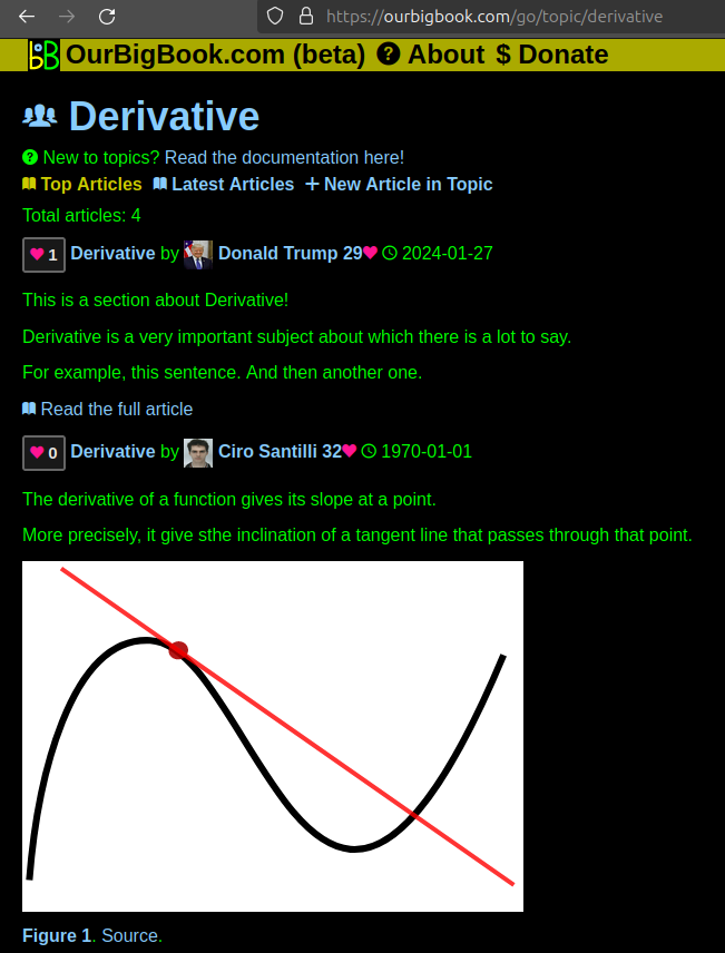
Figure 1. Screenshot of the "Derivative" topic page. View it live at: ourbigbook.com/go/topic/derivativeVideo 2. OurBigBook Web topics demo. Source. - local editing: you can store all your personal knowledge base content locally in a plaintext markup format that can be edited locally and published either:This way you can be sure that even if OurBigBook.com were to go down one day (which we have no plans to do as it is quite cheap to host!), your content will still be perfectly readable as a static site.
- to OurBigBook.com to get awesome multi-user features like topics and likes
- as HTML files to a static website, which you can host yourself for free on many external providers like GitHub Pages, and remain in full control

Figure 2. You can publish local OurBigBook lightweight markup files to either OurBigBook.com or as a static website.
Figure 3. Visual Studio Code extension installation.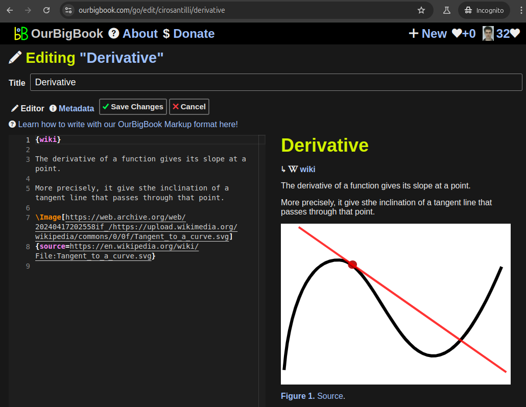
Figure 5. . You can also edit articles on the Web editor without installing anything locally. Video 3. Edit locally and publish demo. Source. This shows editing OurBigBook Markup and publishing it using the Visual Studio Code extension. 
- Infinitely deep tables of contents:


All our software is open source and hosted at: github.com/ourbigbook/ourbigbook
Further documentation can be found at: docs.ourbigbook.com
Feel free to reach our to us for any help or suggestions: docs.ourbigbook.com/#contact