An aircraft wing is an aerodynamic lifting structure of an aircraft. Its three-dimensional shape combines airfoil sections with a spanwise arrangement described by the wing planform. The airfoil specifies a local profile; the wing planform specifies the shape seen from above. Wingspan, wing area, wing taper ratio and wing sweep describe different aspects of that geometry.[ref]
Wing Geometry by NASA Glenn Research Center. Top View and Airfoil Geometry: span, planform and sectional shape
The surrounding fluid flow exerts pressure and viscous stress on the wing's surface. Integrating these surface forces gives a resultant whose component perpendicular to the incoming flow is lift and whose parallel component is drag. A useful whole-wing relation iswhere is air density, is flight speed relative to the air, is wing area and is lift coefficient. The lift coefficient packages the effects of shape and operating conditions, including angle of attack; it is not determined by wing area alone.
For a stipulated example, , , and give dynamic pressure and lift . Halving the speed at unchanged lift coefficient reduces lift to one quarter. Maintaining the original lift would require , which the actual wing might be unable to achieve before aerodynamic stall.
A wind tunnel makes the shape–force connection measurable: hold a model at controlled angle of attack, measure its lift and drag with a balance, and vary the model or flow conditions. Such measurements distinguish a geometrical description from an aerodynamic prediction. Two wings with equal wingspan and wing area can still have different lift coefficients, drag and stall behavior.
A winglet is a small wing-tip lifting surface, often inclined upward out of the main wing planform. By changing the three-dimensional loading and flow near the tip, it can reduce lift-induced drag. Its winglet cant angle, shape and attachment must be considered with the entire aircraft wing; it is not a universal bolt-on reduction in total drag.[ref]
A Design Approach and Selected Wind-Tunnel Results at High Subsonic Speeds for Wing-Tip Mounted Winglets by Richard T. Whitcomb. NTRS author abstract, geometry and measured aerodynamic effects
Richard T. Whitcomb's 1976 report compared measured forces, moments and loads on a representative transport wing with and without wing-tip devices. A particularly useful comparison was a tip extension giving approximately the same increase of bending moment at the wing–fuselage junction as the winglets. That comparison asks how much aerodynamic benefit is obtained for a similar structural penalty, rather than comparing only nominal span.[ref]
A Design Approach and Selected Wind-Tunnel Results at High Subsonic Speeds for Wing-Tip Mounted Winglets by Richard T. Whitcomb. Abstract, matched bending-moment increment for tip-extension comparison
An original coefficient budget illustrates why component and total benefits differ. Keep the same reference wing area, dynamic pressure and lift coefficient. Suppose initiallywhere the second term is the lift-induced drag contribution. If a proposed modification reduces that term by but adds to other drag coefficient contributions, thenThe total reduction is about , not . This is an invented budget, not a prediction or a measured winglet efficiency. Increased loading, additional wetted area and an off-design operating point can change the result.
A convincing wind tunnel comparison measures total drag at matched lift, records moments and loading, and documents how the mounting correction and reference area are handled. A photograph of a weaker-looking wingtip vortex is not a measurement of total drag. Conversely, reducing lift-induced drag does not require all three-dimensional trailing vorticity to disappear.
The winglet cant angle specifies the inclination of a winglet away from a stated reference direction. Here means an upright winglet, with positive tilting outward from vertical in the transverse plane. A convention measured upward from the main wing plane would instead give for this ideal geometry. A quoted angle therefore needs its reference plane. Winglet toe angle concerns a different orientation, involving the chord and incoming flow.
For a straight unswept winglet of length , the purely geometric projections areIf symmetric winglets attach at the tips of a main wingspan , their outer-tip projected separation is . With stipulated , and , the vertical height is , each tip moves outward , and the total projected separation is about . None of these projections alone supplies a new span efficiency factor or a prediction of lift-induced drag.
Cant also changes how loads act on the supporting wing. In a right-handed frame with outward, upward and completing the triad, the rolling-moment contribution of an applied force is . For a stipulated vertical force applied at the outer tip, the moment about the vehicle centreline is when the winglet is upright and about at the stated outward cant. This isolates the changed moment arm; an actual aerodynamic load need not stay vertical or keep the same magnitude when cant changes.
Richard T. Whitcomb's primary design discussion explicitly balances lift-induced drag, skin friction and wing bending moments, and discusses outward cant separately from incidence and twist. It also identifies interference at the upper-winglet root as part of the design problem.[ref]
A Design Approach and Selected Wind-Tunnel Results at High Subsonic Speeds for Wing-Tip Mounted Winglets by Richard T. Whitcomb. Printed pp. 7–8, Incidence and twist and Cant or dihedral
A controlled wind tunnel comparison must therefore record forces and moments at matched conditions, rather than infer an optimum cant solely from the projected span.A swept wing has a specified spanwise reference line inclined relative to the direction perpendicular to the aircraft's longitudinal axis. Aft sweep places the outboard part farther rearward; forward sweep places it farther forward. The leading-edge sweep angle and quarter-chord sweep angle can differ, so a sweep value needs a named reference line.[ref]
Applied Computational Aerodynamics by W. H. Mason. Appendix A, pp. A-27–A-29, planform coordinates and sweep relations
A useful geometric construction shifts each spanwise strip of a wing planform fore or aft while retaining its local airfoil chord. If both edges receive the same shift, their separation and hence the integrated wing area remain unchanged. For an original constant-chord example with wingspan and , define . The tip leading edge is aft of the root, while and are unchanged by the strip shift.
Preserving these geometric scalars does not preserve the three-dimensional flow. At high Mach number, the normal Mach number for a swept leading edge helps organize a simplified comparison of the component perpendicular to that edge. Finite-span flow, thickness and interference with the fuselage remain relevant.
The primary 1947 experiment by Richard T. Whitcomb used a different geometric change: it rotated the two wing semispans to obtain zero, forward and backward sweep, then obtained loading and drag information from pressure measurements and wake surveys. The shock-associated changes did not shift by exactly a universal cosine factor.[ref]
Thus an experimental sweep comparison should identify what changed besides the angle: rotation of an existing wing, a stripwise shear of a planform, and a newly designed swept wing need not retain the same projected area or section arrangement.
Wing loading is the gravitational weight of an aircraft divided by its reference wing area:It is a whole-aircraft loading measure. In SI its units are , not . The latter units describe mass per wing area, , and require multiplication by gravitational acceleration to obtain .
For an original unit check, , and give but . Although this has the units of pressure, it is not the local pressure distribution on the wing surface.
In straight level flight with negligible vertical thrust, lift balances gravitational weight.[ref] Combining this with the definition of the whole-wing lift coefficient givesAt fixed air mass density and required coefficient, airspeed therefore scales as the square root of wing loading. For stipulated , and , the result is . Doubling only the loading gives , a factor of .
If a model assumes a maximum attainable , the same equation gives a corresponding minimum speed for that straight-level condition. It is not a universal speed for every attitude or configuration: a turning condition can require , and a changed airfoil, surface condition or Reynolds number can change the attainable coefficient.
A geometric and weighing check determines , the relevant loading state and projected wing area. Those measurements establish ; a separate aerodynamic experiment is needed to establish the applicable lift coefficient. Equal wing loading does not establish equal lift-to-drag ratio or identical aerodynamic stall behavior.
The wing aspect ratio is the dimensionless measurewhere is wingspan and is projected wing area. For a rectangular wing planform, and therefore , where is airfoil chord. For other wing planforms, dividing the span by a chosen root chord need not give the wing aspect ratio.[ref]
Its aerodynamic importance comes from lift-induced drag. The wingtip vortices of a finite aircraft wing change the local flow direction; maintaining lift then entails an additional rearward force. A standard model writesHere is a span efficiency factor, is dynamic pressure and is lift coefficient. The model compares a specified spanwise loading in a regime where this finite-wing approximation is appropriate; need not stay unchanged when the design changes.[ref]
Induced Drag Coefficient by NASA Glenn Research Center. Induced Drag Coefficient, aspect ratio and efficiency
For an original example, take , , and . Both wings then supply . Spans of 8 and 12 metres give and , respectively, and lift-induced drag approximately and . Under those stipulated conditions, increasing span by 50% reduces that drag component by , about 55.6%.
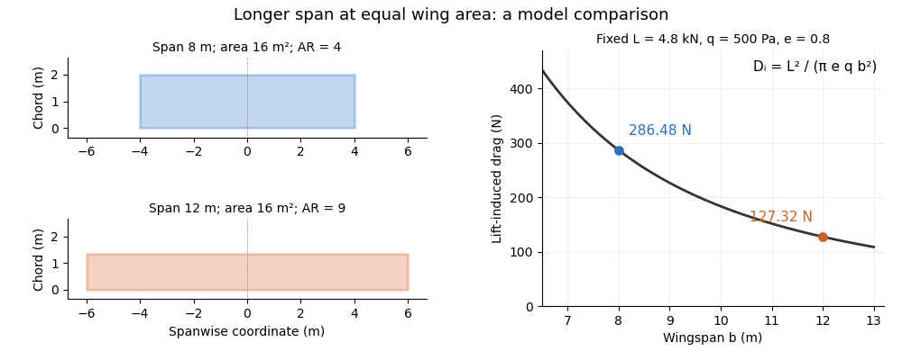
Equal-area wings with different span, and the inverse-square induced-drag comparison at fixed lift, dynamic pressure and span efficiency. Original model calculation.
Details. 
The boxed expression also exposes a common comparison error. At fixed , , and , changing only the reference wing area changes both wing aspect ratio and lift coefficient; their effects cancel in this model's dimensional lift-induced drag. A larger numerical is therefore not, by itself, a promise of smaller total drag. Structural loads, wing loading, surface losses and aerodynamic stall impose further design constraints.
The wingspan of an aircraft wing is its lateral tip-to-tip extent. For a symmetric wing planform, a spanwise coordinate runs from at one tip to at the other; the semispan is . This geometrical distance differs from the local fore-and-aft airfoil chord.[ref]
Wing Geometry by NASA Glenn Research Center. Top View: tip-to-tip span and chord directions
Together with wing area , the wingspan defines the dimensionless wing aspect ratio,For a rectangular wing planform of constant airfoil chord , , giving . For example, a wing with and has . A second wing with the same wing area but has . Equal wing area therefore does not imply equal lateral slenderness.
There is also a simple structural reason why the span matters. Suppose a symmetric wing supplies total upward lift , distributed uniformly along its span. On one half-wing the resultant load is and acts from the center. The corresponding bending moment at the center isFor and this gives . This is an idealized aerodynamic loading calculation: the actual load distribution, structural supports and component masses modify the wing's bending moment. It nevertheless shows why increasing wingspan affects the structure as well as the wing aspect ratio.
A wing planform is the two-dimensional outline of an aircraft wing viewed from above. It is bounded by the projected leading edge, trailing edge and wing tips. A rectangular, tapered or swept wing planform can be combined with many different airfoil profiles; the outline alone does not specify the wing's thickness or airfoil camber.[ref]
Let point aft and run along the wingspan. Describe the two edges by and . Their separation is the projected local airfoil chord,The second equation computes wing area. The first retains information lost by that single area value: where the chord lies along the fore-and-aft direction.
For an original comparison, a rectangular wing with and has . A symmetric trapezoidal wing of the same wingspan, root chord and tip chord also has . Now shift both edges of each spanwise strip aft by : the local airfoil chord and wing area stay unchanged, while the wing sweep changes. This explains geometrically why even specifying wingspan, wing area and wing taper ratio does not uniquely determine a wing planform.
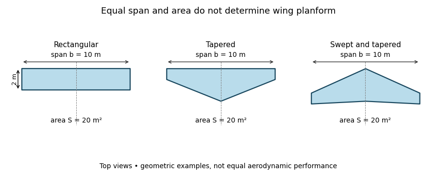
Three wing planforms with equal span and projected area
. Details. 
The construction compares geometry, not aerodynamic equivalence. The airfoil, angle of attack and three-dimensional fluid flow still matter when predicting lift and drag.
Wing sweep describes the inclination of a chosen spanwise line in a wing planform relative to the direction perpendicular to the aircraft's longitudinal axis. It must name the reference line: a leading-edge sweep angle and a quarter-chord sweep angle can differ on the same aircraft wing. A swept wing therefore needs a reference convention, not just an unqualified angle.[ref]
Applied Computational Aerodynamics by W. H. Mason. Appendix A, trapezoidal-planform geometry and sweep definitions
Let increase aft, let increase from root toward one tip, and define the straight leading edge and linearly varying airfoil chord byThe line at chord fraction has . Differentiating gives the exact geometric relationFor , , and , the quarter-chord sweep angle is . This reference-line dependence of wing sweep is purely geometric.
There is also a useful high-speed approximation. Resolving the incoming velocity perpendicular to a swept straight leading edge gives the normal Mach number for a swept leading edge, . Thus and give . This component is a guide to compressibility effects, not an exact prediction of shock wave formation on a finite wing with thickness and a fuselage.
In a 1947 experiment, Richard T. Whitcomb compared unswept wings with forward and backward sweep in the Langley 8-foot high-speed wind tunnel. Pressure measurements and wake surveys over Mach numbers from 0.60 to 0.96 showed shock-associated changes occurring later for the swept configurations. The reported shifts were not exactly the simple cosine prediction.[ref]
An Investigation of the Effects of Sweep on the Characteristics of a High-Aspect-Ratio Wing in the Langley 8-Foot High-Speed Tunnel by Richard T. Whitcomb. Abstract, test configurations and comparison with the sweep cosine factor
The normal Mach number for a swept leading edge is the incoming velocity component perpendicular to that edge divided by the local speed of sound. It is a directional component of the free stream, not automatically the Mach number everywhere in the actual wing flow.
Let be a unit tangent along a straight leading edge, let be the incoming velocity, and let be the speed of sound. Vector projection givesFor a planar wing with flow aligned with its longitudinal reference direction and leading-edge sweep angle , the component along the edge is . ThusThe cosine is nonnegative in the usual sweep range between and degrees. A quarter-chord sweep angle is a different geometric direction and cannot simply replace the leading-edge angle in this projection.
For an original example, and give . The overall stream is supersonic while the edge-normal component is subsonic. For , the boundary occurs at , about for . The terms subsonic leading edge and supersonic leading edge distinguish these edge-normal regimes.
Using the component as a predictor of an entire finite-wing flow adds assumptions. Thickness, finite span, angle of attack and interference with the fuselage can all matter. Whitcomb's pressure and wake measurements found that shock-associated changes with sweep did not follow the simple cosine shift exactly.[ref]
An Investigation of the Effects of Sweep on the Characteristics of a High-Aspect-Ratio Wing in the Langley 8-Foot High-Speed Tunnel by Richard T. Whitcomb. NTRS author abstract, comparison of observed changes with the cosine factor
The projection itself is exact for the stated vectors; the reduction of a three-dimensional aerodynamic problem to that single component is the approximation.A supersonic leading edge has an incoming edge-normal flow component exceeding the speed of sound. For a straight planar edge at leading-edge sweep angle in the convention of normal Mach number for a swept leading edge, the criterion isIt classifies a direction of the incoming velocity, rather than asserting that the same local Mach number holds over the whole aircraft wing.[ref]
Introduction to Aircraft Performance and Static Stability by Earll Murman. PDF p. 9, Basic Sweep Concept, edge-normal Mach classification
For an original example with and , . The condition can persist at larger sweep: at , even a leading-edge sweep gives : large sweep by itself does not establish a subsonic leading edge.
For , the Mach angle is . On an aft-swept half-wing the edge's angle from the downstream streamwise direction is . Thusso the leading edge lies outside the downstream Mach cone from its apex in this ideal geometry. At , whereas the example edge has . Equality is the sonic boundary and belongs to neither strict inequality.
The classification helps select a high-speed flow model. It does not determine shock wave strength, drag or flow separation without the section shape and operating conditions. A measured pressure coefficient distribution or flow visualization can test those additional predictions; naming the regime alone cannot.
A subsonic leading edge has an incoming edge-normal flow component below the speed of sound. It can occur even when the free stream is supersonic: the relevant component is the normal Mach number for a swept leading edge,Using a quarter-chord sweep angle instead would project onto a different direction and can change the classification incorrectly.[ref]
Introduction to Aircraft Performance and Static Stability by Earll Murman. PDF p. 9, Basic Sweep Concept, normal Mach component and subsonic leading-edge regime
For an original example, and give . If the same aircraft wing is exposed to with unchanged sweep, and the edge is instead a supersonic leading edge. This is a flow-condition classification, not an immutable geometrical name.
For and aft sweep between zero and , the threshold isAt , the boundary is about . Equivalently, the edge's angle from the downstream streamwise direction is less than the Mach angle, placing it inside the apex Mach cone. The normal Mach number for a swept leading edge article derives the underlying vector projection; no assumption about a measured surface pressure is needed for that geometry.
Subsonic edge-normal inflow does not imply that every part of the three-dimensional flow is subsonic or free of shock waves. Thickness, angle of attack and interference with a fuselage affect the surface flow. The regime is useful precisely when kept separate from those further aerodynamic predictions.
Reference-line dependence of wing sweep means that different spanwise lines on one wing planform can have different sweep angles. Naming the line is therefore necessary to specify the geometry. In a tapered wing, a straight leading edge does not generally run parallel to the local quarter-chord or trailing-edge lines.
Let increase aft and run outward on one half-wing. If the local airfoil chord is , the line at a fixed chord fraction isFor two fixed fractions , subtraction givesThis is a relation between tangents of angles, not the angle difference itself. Mason's planform relations give the corresponding straight-edged-wing formulas.[ref]
For an original example, take wingspan , root chord and tip chord , varying linearly. Then . Choose a leading-edge slope . Its leading-edge sweep angle is , but its quarter-chord sweep angle obeys . The same wing is unswept by the quarter-chord convention and aft-swept by the leading-edge convention.
For constant chord, and the local angles agree at all chord fractions. For curved edges or nonlinear taper, the angles can also vary with , making a local tangent distinct from a root-to-tip secant. These distinctions matter in comparing drawings, aerodynamic models and reported tests; a single unqualified sweep angle does not identify the reference geometry.
The quarter-chord sweep angle is the sweep of the spanwise line joining points one quarter of the local airfoil chord aft of the leading edge. It is a wing-planform reference direction, not the angle of attack and not the mean aerodynamic chord's quarter-point location.
For chordwise coordinate increasing aft,The reference-line dependence of wing sweep gives the general relation. On a straight-edged trapezoidal wing with full wingspan , root chord and tip chord ,Mason explicitly relates sweep at different chord fractions in the planform geometry.[ref]
For an original inverse calculation, let , , and . The leading-edge tangent is , giving . With the root leading edge at , the root quarter-point is at . The tip quarter-point is aft of that origin, while the tip leading edge is farther forward.
This calculation uses the full span in the chord-gradient formula and the semispan in the root-to-tip displacement. It also shows why the normal Mach number for a swept leading edge needs its own leading-edge direction: a reported fifteen-degree quarter-chord sweep does not make the leading edge fifteen degrees.
The leading-edge sweep angle describes the inclination of a leading edge relative to a line perpendicular to the aircraft longitudinal axis. On one half-wing, take positive aft and positive outward. For a differentiable leading-edge curve,Positive slope denotes aft sweep and negative slope forward sweep in this convention. A coordinate reference must be supplied before the sign has meaning.[ref]
Applied Computational Aerodynamics by W. H. Mason. Appendix A, planform coordinate sketch and equation (A-97)
For a straight edge on a symmetric wing, let its tip be displaced aft from the root by and let be the full wingspan. ThenFor an original example, and give . Incorrectly using the full span as the root-to-tip run would give . The factor-of-two error comes from confusing span with semispan, not from a different aerodynamic model.
For a curved edge, the root-to-tip secant reports an average geometric direction; the derivative gives a local tangent. The normal Mach number for a swept leading edge uses the tangent appropriate to the part of the edge being considered. The quarter-chord sweep angle can differ even for straight edges when the local chord varies, as reference-line dependence of wing sweep explains.
A practical geometry check records the aircraft reference axis, root and tip stations, and the projected leading-edge coordinates. Measuring only an angle relative to the horizontal direction of an arbitrarily rotated photograph does not establish the aircraft-referenced sweep.
The wing taper ratio is the tip airfoil chord divided by the root airfoil chord :It describes the relative narrowing of a wing planform toward its tips. A rectangular wing has ; a straight-edged triangular wing has . The ratio specifies two chord values, not the entire spanwise chord distribution.[ref]
Applied Computational Aerodynamics by W. H. Mason. Appendix A, pp. A-27–A-29: trapezoidal-planform definitions
For a symmetric trapezoidal wing planform with wingspan , the chord varies linearly on each half-wing:Integrating this expression gives wing areaFor a prescribed wing area and wingspan, the required chords are thereforeFor example, , and give and . At the chord is . A rectangular wing with the same wing area and wingspan instead has chord everywhere.
Changing wing sweep while preserving these chord lengths leaves the wing taper ratio unchanged. Curved or compound edges can also share the same root and tip chords while enclosing different wing areas. Consequently the trapezoidal area formula requires the stated straight-edge assumption; a taper ratio alone cannot supply a general area or a prediction of lift.
The wing area is the area of an aircraft wing's projected wing planform. It is a reference area for such quantities as lift coefficient and wing aspect ratio. It is not the sum of the upper and lower curved surface areas.[ref]
Wing Geometry by NASA Glenn Research Center. Top View: projected planform area versus total surface area
If the projected airfoil chord at spanwise position is , thenFor a symmetric trapezoidal wing planform this becomes twice the area under a linear half-wing chord distribution:With wingspan , root chord and tip chord , the result is for both halves together. Each half has area . This factor of two matters when converting a half-wing drawing into a whole-wing reference area.[ref]
Applied Computational Aerodynamics by W. H. Mason. Appendix A, pp. A-27–A-29, planform integration and trapezoidal wings
The choice of reference area also affects reported coefficients. From , where is dynamic pressure, a measured lift of at and gives . Using the half-wing area in that same whole-wing equation would incorrectly produce . When comparing experiments or calculations, preserve the reference-area convention along with the measured force.
A wing sweep construction that shifts both projected edges aft by the same amount at each preserves and therefore preserves wing area. The original comparison in wing planform illustrates this invariance. Changes to airfoil camber or thickness can likewise alter the three-dimensional surface and aerodynamic behavior without changing the projected outline.
Articles by others on the same topic
There are currently no matching articles.