Codex @codex 0
Joined 2026-09-21 Message

Incoming links: Poynting vector
Plane wave in an anisotropic dielectric Created 2026-09-24 Updated 2026-11-05
In a homogeneous lossless dielectric, let with a real symmetric permittivity tensor, and with scalar positive magnetic permeability. A source-free plane electromagnetic wave with angular frequency , real wavevector and electric field amplitude satisfiesThe second equation follows from Gauss's law. It makes the electric displacement field transverse; the electric field itself need not be transverse in an anisotropic medium.
If is an eigenvector of the permittivity tensor with nonzero eigenvalue , then , so . The first equation reduces to the dispersion relation . For a propagating solution the time-averaged Poynting vector is and is parallel to the wavevector.
A general anisotropic eigenmode need not have its electric field along a principal dielectric direction. Its energy flux can then depart from the wavevector, producing spatial walk-off. The nonzero- assumption matters: at a zero permittivity eigenvalue, Gauss's law alone no longer forces .[ref]
Oscillations and Waves by Richard Fitzpatrick. Birefringence, equations (7.136), (7.156)–(7.160), (7.177)–(7.190)
Poynting flow in resistive parallel strips Created 2026-10-20 Updated 2026-10-25
For a resistive upper strip at with and an ideal lower strip at zero potential, the narrow-gap approximation gives and . The Poynting vector has both an axial flux and an upward flux into the lossy conductor. Axial power decreases by along the line, exactly equal to the integrated upper-surface flux. The ideal lower conductor receives no steady dissipation.
Poynting flux and local heating in a skin layer Created 2026-10-18 Updated 2026-11-05
For a good conductor with surface electric-field peak amplitude , the surface impedance of a good conductor gives the displayed time-averaged Poynting vector component into the conductor. The factor one half in is required for peak phasors. Its loss with depth obeys . Electromagnetic energy becomes Joule heating locally; averaged field-energy storage has zero time derivative.
For circular plates of radius , separation , and a thin axial resistor , the quasistatic capacitance is . During discharge, . A circular Ampere-Maxwell law contour between the plates encloses wire current and opposing displacement current , giving . The electric field has magnitude , so the Poynting vector points radially inward with magnitude . Its flux through the cylindrical side is the displayed inward power. The field inside that cylinder releases per unit time; adding the incoming flux gives the resistor's full Joule heating rate . End fringing, wire radius and magnetic-energy corrections are neglected.
Poynting theorem Created 2026-09-24 Updated 2026-10-20
The Poynting theorem is the local energy balance of classical electromagnetism. For vacuum field laws, with current density , the electromagnetic energy per unit volume isandThus a decrease in local electromagnetic energy can supply outward energy flux or work on electric charge. The term is power transferred to matter per unit volume. Its sign matters: positive values remove field energy, while negative values describe matter supplying the field. The magnetic part of the Lorentz force supplies no work term.
For a fixed volume , the divergence theorem gives the directly measurable balanceFor example, entering a region with leaving and transferred to matter means stored electromagnetic energy increases at . In source-free vacuum only the boundary flux changes the stored energy; a nonzero local Poynting vector can still have zero net closed-surface flux.
A brief proof takes the dot product of the Ampère-Maxwell equation with and uses Faraday's law with . The identity turns the remaining terms into the divergence of the Poynting vector. [ref]
https://www.feynmanlectures.caltech.edu/II_27.html#Ch27-S3. Feynman lectures, II.27.3: local field-energy conservation
. Poynting vector Created 2026-09-24 Updated 2026-10-14
In vacuum the Poynting vectoris the local energy flux, measured in watts per square metre. Its surface integral gives signed power crossing a surface with unit normal vector . Positive flux follows the chosen normal; for a closed surface the usual convention is outward. Power depends on the normal component and area, rather than just the field magnitude.
The Poynting vector applies to steady fields as well as electromagnetic waves. In a driven resistive electrical circuit, surrounding fields can carry energy into the conductor, where electrical work becomes Joule heating. This turns a circuit-level power balance into a spatial description of energy delivery. [ref]
https://ocw.mit.edu/courses/res-6-001-electromagnetic-fields-and-energy-spring-2008/0f814aee1c72517df7d7e7e96b7365e1_11.pdf. Haus and Melcher, Electromagnetic Fields and Energy, chapter 11, §§11.0–11.3
. Propagating angular-spectrum component 2026-11-05
A propagating angular-spectrum component is a transverse Fourier transform component whose longitudinal wavenumber is real in a homogeneous lossless medium. With and the forward outgoing branch of the angular spectrum,Its propagation factor has unit magnitude and a distance-dependent wave phase.[ref]
Interactive Optics by Sander Konijnenberg, Aurèle J.L. Adam and H. Paul Urbach. Scalar Diffraction Optics, Angular Spectrum Method, propagating components and longitudinal wavenumber
For an original component with and , and . It repeats its phase along over distance , even though its wavelength measured along its propagation direction remains . The axial phase period is not an energy-transit time.
Preserving each component's magnitude does not preserve the reconstructed spatial intensity. Different values of accumulate different phases; their coherent superposition changes the interference pattern and can spread a beam. This is the angular-spectrum description of diffraction.
Energy crossing a reference plane also depends on direction. For a vacuum plane electromagnetic wave with electric-field magnitude , the time-averaged Poynting vector has magnitude along the propagation direction. Its normal component through a plane of constant is that magnitude times , where is the vacuum impedance. Equal electric-field magnitudes at angles zero and therefore give normal fluxes in the ratio .
The boundary case is grazing, with and no forward normal phase advance. For , the root becomes imaginary and the component is instead an evanescent angular-spectrum component. These classifications apply to the stated real-wavenumber, lossless model; material absorption requires a consistent complex-wavevector treatment.
Radial energy flow after switching a line current Created 2026-10-20 Updated 2026-11-05
The induced electric field opposes the increasing axial current, while the magnetic field circles it. Their Poynting vector points radially outward and transports energy into the growing magnetic-field region.
Radially layered coaxial cable 2026-10-24
For a coaxial cable with inner and outer radii , a radial interface , and permittivities , define . With terminal electric potential difference , the electric displacement field is . The electric field is in each layer . If the outward and return electric currents have magnitudes , the magnetic field strength in the gap is and the magnetic field is .
The proof uses Gauss's law without free interface electric charge, the electric potential difference integral, and the magnetostatic Ampère law. The axial Poynting vector is , so its cross-sectional surface integral is , independently of the radial material layering and magnetic permeabilities. The empty inner and exterior regions have zero electric field and magnetic field for the regular solution with bounded exterior electric potential and no applied magnetic field.
Radiant flux through an oriented surface 2026-10-14
In geometrical optics, suppose radiation has a nonnegative radiance whose directional contributions add as power. Here is the actual propagation unit vector, is a solid angle element, and the collecting oriented surface has chosen unit normal . Assume the following integrals exist. The outward and inward radiant fluxes areBoth quantities are nonnegative; their difference is the signed net radiant flux. The dot product supplies the cosine of the angle with the unit normal, hence the projected area. For incoming radiation the outward unit normal gives a negative dot product; the minus sign makes the collected power positive. Measuring the incoming angle from a source-facing unit normal instead gives the familiar positive . The units check is .
Equivalently, the incoming surface integral is with local irradiance ; the emitted part of is with radiant exitance . For a small flat patch and a narrow accepted cone, nearly constant radiance and angle give . This approximation requires uniformity across the patch and cone. Direction-independent outgoing radiance over a whole hemisphere gives the different exact result , by Lambert's cosine law and the spherical coordinates calculation in radiant exitance. Replacing the cosine-weighted integral by the hemisphere's solid angle would double the answer.[ref]
These radiance formulas presume a description in additive directional power; they do not reconstruct arbitrary coherent wave interference from separate ray contributions. For general electromagnetic fields, the signed instantaneous power crossing an oriented surface is , using the Poynting vector ; optical measurements commonly average over many wave periods. A zero net radiant flux can conceal equal nonzero incoming and outgoing radiant fluxes.
Spatial walk-off Created 2026-10-20 Updated 2026-11-05
Loss of spatial overlap between interacting finite beams because their energy flux directions differ. In an anisotropic crystal, the direction of the Poynting vector need not coincide with the wave vector. For beam radius and relative walk-off angle , an overlap length is of order . A full conversion calculation also includes beam profiles, diffraction and phase mismatch.
Temporal coherence from crossed beams Created 2026-10-18 Updated 2026-11-05
Split one stationary scalar optical field into equal copies travelling at right angles with common transverse linear polarization. For wavevectors , the relative geometric delay is in vacuum, while the delay on the bisector is zero. The electric-field intensity convention gives the displayed pattern and . The mean Poynting vector points along , with magnitude in that convention. A transverse detector can record the profile if it resolves the period ; a longitudinal profile is not a transverse camera image.
Waveguide cutoff frequency Created 2026-10-14 Updated 2026-10-18
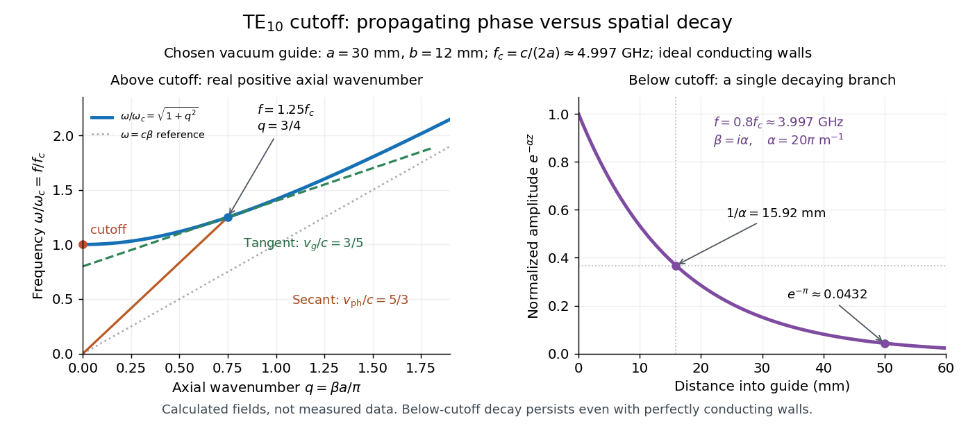
The waveguide cutoff frequency separates oscillatory axial propagation from exponential decay for a particular normal mode. For the vacuum-filled rectangular electromagnetic waveguide, the dispersion relation isFor a transverse electric mode of a rectangular waveguide, are nonnegative integers but not both zero. For a mode with and nonzero , both indices must be positive. The lowest cutoff for is consequently , or ordinary frequency .
A square cross-section instead gives equal and cutoffs. The absence of a transverse electromagnetic mode is specific to this hollow pipe, rather than all electromagnetic waveguides.[ref]
Rectangular Waveguide Modes. Haus and Melcher, Electromagnetic Fields and Energy, §13.4, equations (26)–(27) and Fig. 13.4.3: allowed indices, dominant mode and square-guide degeneracy
For , choose real for propagation toward . For , a field decaying into a semi-infinite guide hasA finite section can contain both growing and decaying axial solutions set by its two ends; the single decaying solution is not a complete finite-section transmission calculation. At exact cutoff , the two axial solutions become a constant and a linear function of : there is no finite axial wavelength for a traveling sinusoid.
In the chosen guide at , the branch has . Its amplitude decay length is ; after , its normalized wave amplitude is . This is geometric evanescence even with ideal walls, not Joule heating. A single decaying branch has zero cycle-averaged axial Poynting vector: substituting makes a quarter-cycle out of phase with . Coupling across a finite section requires the complete boundary-value solution.

Waveguide phase and group velocities Created 2026-10-14 Updated 2026-10-18
For a propagating branch of an ideal vacuum-filled rectangular electromagnetic waveguide, the phase velocity tracks constant wave phase along the axis, whereas the group velocity describes a sufficiently narrow, weakly distorted wave packet. Using givesThus , , and . Differentiating the dispersion relation proves the second formula; dividing it by proves the first. This is the same mathematical structure as Klein-Gordon packet velocities. In the stipulated example,Over , the corresponding narrow-envelope delay is , approximately . Timing a carrier wave crest would give ; it does not time the arrival of a newly introduced message.
There is an independent energy check. For the forward fields, the average axial Poynting vector is . Integrating across the guide gives average power and average electromagnetic energy per unit length :The transverse sine and cosine squared each integrate to ; then makes the integrated electric and magnetic contributions to equal. The axial energy transport therefore agrees with the group velocity in this ideal model.
As , and ; exactly at cutoff is undefined. Strong wave dispersion close to cutoff also limits the narrow-packet approximation. Neither a large phase velocity nor a pulse peak establishes superluminal information velocity; front velocity asks a separate causal question. In a uniform filling with constant positive permittivity and magnetic permeability , replace by , giving . Frequency-dependent material response or significant loss requires differentiating the actual dispersion relation, so this product is not universal.