Source paper: www.whatdotheyknow.com/request/physics_preliminary_examinations/response/1162943/attach/3/Twain.7z?cookie_passthrough=1
Solutions for the ordinary sitting of 3 June 2013, including all four alternatives in Section B. The cover prints the placeholder XXXX; no numerical formal code is inferred from the resit.
The parallel axis theorem states for parallel axes separated by , with the reference axis through the centre of mass. The perpendicular axis theorem states for a planar lamina in the plane, about mutually perpendicular axes through one point. It does not apply directly to a three-dimensional solid.
For the transverse moment of inertia of a uniform solid cylinder, divide the cylinder into thin disks at axial positions . Symmetry and the perpendicular axis theorem give the diametral moment of inertia of each disk; the parallel axis theorem adds . HenceThe thin-disk limit is , while the slender-rod limit is .
A cyclic coordinate is absent explicitly from the Lagrangian: , even though may occur. The Euler-Lagrange equation then givesThus a continuous coordinate-translation symmetry gives a conserved conjugate momentum. The conserved quantity need not be ordinary linear momentum: an absent azimuthal angle can give conserved angular momentum. The derivative is taken holding the other coordinates and velocities fixed.
Define the energy function . Along solutions of the Euler-Lagrange equations,ConsequentlyFor an ordinary isolated mechanical system with , a time-independent quadratic kinetic energy and a velocity-independent potential energy, , so . For a more general Lagrangian, the conserved quantity is the displayed energy function; identifying it with requires these assumptions.
For the relativistic head-on elastic collision with a stationary target, use as stipulated, so masses are measured in energy units. The incoming momentum is and the invariant squared total four-momentum isThe centre-of-mass frame moves at , with . In this frame the incident particle hasA nontrivial head-on elastic collision reverses and preserves . Boosting back to the laboratory frame givesThe no-interaction forward branch instead leaves ; the requested formula describes the actual one-dimensional encounter and recoil.
With and , one also has . The denominator in a is then dominated by , and the numerator by :This residual total energy is still much larger than the incident particle's rest energy , but is a small fraction of its incident energy . The target acquires most of the available energy in this high-energy, heavy-projectile limit.
For , retain the ratio until a further limit is specified. Since , the leading expression from a isFor an infinitely heavy target at fixed incident energy, and : the projectile reverses with negligible target recoil energy. If the incident particle is ultrarelativistic even relative to the target, , the same leading expression instead gives . The mass hierarchy alone does not justify replacing by zero.
For maximum projectile range from an elevated launch, let be horizontal projectile range from the tower and the launch angle above horizontal. The projectile motion trajectory isPut . For a fixed , its largest possible occurs at ; the envelope is . The furthest attainable ground point satisfies , soThe optimum angle is less than for and approaches as . The result is the maximum horizontal distance, using uniform gravity and no drag.
If moves at relative to , the Lorentz transformations areA rod at rest in has length . To measure it in , select endpoint events simultaneous there: , so and . This is length contraction.
Now let a clock at rest in cross the two rod endpoints. These are different events, with , and . Their transformed time interval isThusThe moving clock measures the proper time . The rod's contracted length divided by its speed in that clock's frame gives exactly the same crossing time; time dilation and length contraction are consistent consequences of the same transformation. Measuring a length and measuring a traversal interval require different simultaneity conditions.
Choose the positive axis from the approaching source towards the observer. The photon that reaches the observer is emitted forward, with source-frame four-momentum . Boosting to the observer frame gives , where . Since photon energy is ,This is the approaching-source relativistic Doppler effect. A photon emitted in a general source-frame direction would instead have the factor ; forward emission is the geometry of the photon directed to the observer here.
The alpha particle has electric charge and acquires kinetic energy . For Coulomb head-on closest approach with target recoil, the initially stationary beryllium nucleus is free to recoil. Approximating the nuclear masses by and , the initial relative-motion kinetic energy isAt closest separation the relative radial velocity vanishes, although the centre of mass continues moving. Conservation of energy for the relative motion givesUsing gives . If the nucleus were externally held fixed, the relevant energy would be , yielding instead. Initially stationary is not the same as constrained stationary; the given proton and neutron counts supply the recoil correction. Nuclear sizes and strong interactions are negligible at this separation.
A geostationary orbit has the same angular velocity as the Earth. Let and . Balancing the required centripetal acceleration with the exterior gravitational field givesThe orbital plane must be equatorial and the motion prograde for the satellite to remain over one point. The uniform density assumption supplies in terms of the specified and .
Taking the Earth's sidereal rotation period as , , and givesThe orbital radius is therefore about , or an altitude of about . Replacing the sidereal day by changes this estimate by less than .
For the uniform unloaded space-elevator cable, let the constant linear mass density be and the outer endpoint be . In the co-rotating frame the outward effective force per unit length is . The cable is just clear of the surface, with neither a ground load nor an endpoint counterweight, so both ends have zero applied tension. The integrated effective force must vanish:Using , this becomesThe root is a zero-length cable. The physical nonzero cable hasIt extends well beyond the geostationary orbit so its outer centrifugal force balances the inner segment's weight. If a cable is anchored with a nonzero endpoint load or has a counterweight, that load changes the integrated balance; its length is not fixed by the zero-end-load formula.
An element of the rotating cable satisfiesWith , integration givesIt increases below , decreases above , and returns to zero at . HenceThe tension is greatest at the geostationary orbit, where local effective gravity is zero. A zero local effective force does not mean zero tension: that section transmits the loads of the entire inner and outer cable portions.
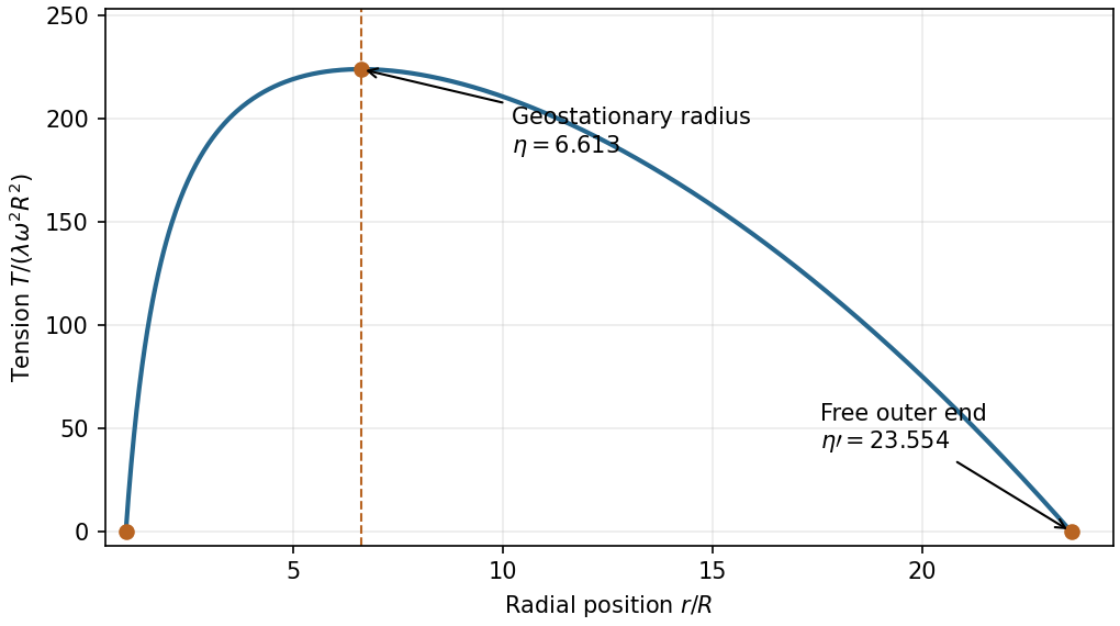
Tension in the uniform unloaded space-elevator cable
. The tension vanishes at both ends and peaks at the geostationary radius. The outer endpoint follows from the integrated rotating-frame force balance, using the specified uniform Earth density. Details.
Let measure the rim point mass's displacement from vertically below the fixed axis. The disk has moment of inertia , and the rim mass contributes another . Its varying gravitational potential energy is . ThusThe disk's centre of mass remains fixed, so its own gravitational contribution is a constant and has been omitted. The total fixed-axis moment of inertia is .
The Euler-Lagrange equation from a is . Linearizing about givesBoth angular frequency and ordinary frequency are given to distinguish the two conventions. The stable position places the extra mass below the pivot.
For the rolling disk with a rim point mass, impose rolling without slipping and take the clockwise angular displacement from the configuration with the extra mass at the bottom. The disk centre has and . The extra mass hasThe disk's translational and rotational kinetic energies sum to . Including the rim mass givesThe exact Euler-Lagrange equation isTo first order, . ThereforeAt the bottom the extra mass is instantaneously at the contact point and has no first-order velocity. The increased effective inertia comes from the moving disk. Static friction enforces the rolling constraint without doing work at the stationary contact.
In the rim-mass pulley coupled to a hanging mass, the printed figure shows the smaller pulley fixed overhead, and the mechanical string leaves the right-hand tangent of the larger pulley. Let increase counterclockwise from the downward vertical to the radius carrying . Then the hanging mass moves downward by . The string is taken to grip the rim without slipping. Its tension must be solved dynamically, rather than set equal to during motion.
The kinetic energy and potential energy areThe Euler-Lagrange equation and the condition for equilibrium areOne can also eliminate the tension from and . For , the solution with is stable; the other solution in a full turn is unstable.
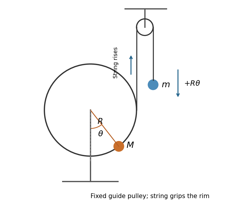

Put at the stable equilibrium. Since , linearization of d givesThusAs , the result approaches , the simple pendulum value. As , the restoring curvature tends to zero and this small-amplitude frequency tends to zero; the endpoint itself is not a stable quadratic minimum.
For the approaching ship, and . Its station-frame length contraction gives . Adding the two station-frame clearances givesThis is the berth's proper length, since the berth is at rest in the station. It is a simultaneous station-frame allocation, not a ship-frame guarantee of a safe docking maneuver.
The berth moves at in the ship's initial rest frame, so it too is subject to length contraction:The ship remains long in this frame. The two length comparisons use different simultaneous endpoint events; this is the same relativity of simultaneity that resolves the ladder paradox. Physical docking also requires deceleration, whose later effects are outside these initial inertial measurements.
Interpret the one-light-day separation as measured in the station frame at capsule launch, and retain the ship's initial inertial rest frame until reception at the station. The phrase does not explicitly name a frame; an alternative is given below. The ship-frame simultaneous separation is . The capsule moves at towards a station approaching at , so their separation decreases at in this frame. This is a separation rate, not either object's speed. Hence the elapsed ship-frame coordinate time isIt is the interval assigned using synchronized clocks in the ship frame to the launch and remote arrival. A single onboard clock does not directly mark the remote arrival event; observing its arrival signal would add a light-travel delay. If the stated one-light-day separation were instead measured in the ship frame, the answer would be .
Launch and arrival occur on the capsule's own worldline, so its clock measures the proper time. In the ship frame its Lorentz factor is ; thereforeThis uses the station-frame distance convention stated in i. With a one-light-day distance in the ship frame instead, it becomes . The uncertainty is a distance-frame convention in the wording, not a missing figure or an unanswered mathematical part.
The velocity-addition formula combines the ship's station-frame velocity and the capsule's ship-frame velocity:For the distance convention in i, station-frame arrival takes . Transforming its two endpoint events back to the ship frame gives , agreeing with i. The capsule remains below the speed of light in either frame.
The capsule continues inertially at while the ship reduces its station-frame speed to . Transform the ship's new velocity into the capsule frame:Thus its speed is , and the negative sign means it recedes behind the capsule along the chosen axis. The same transformation compares the subsequent local inertial velocities; the details of the intervening deceleration are not needed.
Let and use plane polar coordinates in the orbital plane. The Newtonian gravitational potential energy is , soA central force keeps the orbit in a plane. The star is treated as stationary, appropriate when ; otherwise the two-body reduction uses the reduced mass and the relative separation.
The Lagrangian has no explicit time dependence, so its energy function is constant. With total speed , division by givesConsequently, between the initial point and any other point,This energy relation holds for nonradial motion too. Radially outward motion is the stipulated approximation for the subsequent probe calculation; angular momentum is then zero.
Retain the source's idealized solar radial trajectory. Use , and . At ,The speed has decreased because the probe gains gravitational potential energy while moving away from the Sun. This is the supplied simplified model, rather than a reconstruction of Voyager 1's actual three-dimensional trajectory or planetary encounters.
Setting in b gives the asymptotic speedThe radicand is positive, so the ideal probe has positive total mechanical energy and escapes the Sun. The later dust-cloud model takes this limiting speed as its initial speed.
For constant-area capture of stationary dust, let at cloud entry, , , and define with fixed collecting area . Every swept volume adds stationary mass, soThere is no external longitudinal force, and the incoming dust has zero momentum in the cloud frame. The variable-mass system therefore satisfies , rather than . Using givesHenceThe kinetic energy decreases during sticking: . The lost energy becomes internal energy. Radiation, gravity, sputtering and changes in area are excluded by the ideal complete-collection model. The zero-density limit recovers , and .
Articles by others on the same topic
There are currently no matching articles.