These solutions use the ordinary sitting. The cover gives 2019 although the annual release is named 2018. The tunnel formula in question 1 requires a ceiling-height regime, and the offset circular orbit in question 8(c) is singular where it meets the force centre.
For a launch angle , the projectile motion equations give a flight time , a projectile range , and an apex height . Thus the ceiling requires .
Set . Then , which increases up to . The optimum is therefore , giving the projectile range under a ceilingThe printed expression is valid in the first regime. A higher ceiling leaves the usual launch admissible, so it cannot reduce the maximum range. The angle in the ceiling-limited regime is . Equality at the roof is allowed in this ideal geometrical model; if touching the roof is forbidden, the same value is a supremum approached from below.
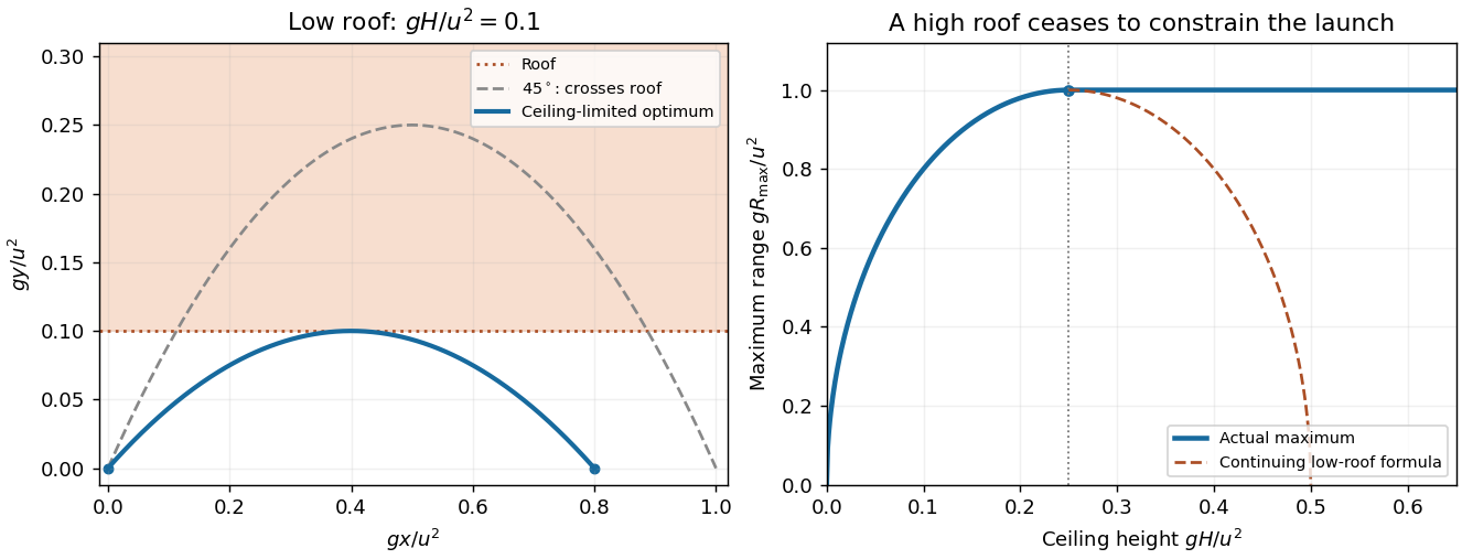
The tunnel ceiling limits low launches, while a sufficiently high roof leaves the ordinary maximum range unchanged
. Details. 
Let be the relative velocity and the centre-of-mass velocity. Inverting givesSubstitute into the sum of the two kinetic energies. The cross terms cancel, while the coefficient of is the reduced mass . HenceThe first term is translation of the centre of mass; the second is the kinetic energy measured in the centre-of-momentum frame. For an isolated perfectly inelastic collision, the bodies finish with a common velocity, while their total momentum and thus are unchanged. The kinetic energy converted to internal forms is thereforewhere is their initial relative speed. Total energy remains conserved; it is the translational-plus-relative kinetic energy that decreases.
Measure position along the ideal thin rod from its centre of mass. Its perpendicular distance from the inclined axis is , and its linear mass density is . The moment of inertia is thereforeThis tends to zero for an axis along an infinitely thin rod and to for a perpendicular central axis. A finite rod thickness would add a contribution absent from the stated thin-rod model.
The parallel axis through the centre is the rod's own long axis, with zero moment of inertia in the thin-rod approximation. By the parallel axis theorem, the displaced parallel axis hasEquivalently, every mass element is the same perpendicular distance from that axis, so the defining integral immediately gives this result.
Write the incoming particle speed as , its final signed speed as , and the rod's final centre-of-mass velocity along the impact direction as . Let be the signed impact distance from the centre, and choose the sign of the angular velocity so that the contact point's velocity component is . The rod's central moment of inertia is .
The impulse delivered to the rod is . Conservation of linear and angular momentum givesUsing these in conservation of kinetic energy,This is the equal-mass instance of the effective contact mass calculation. For , both final speeds are nonnegative, so equal speeds require . Therefore andBoth symmetric impact points lie on the rod, since .
More generally, the relative contact velocity immediately afterwards isThus its magnitude equals the incoming relative speed and its direction reverses. At the specified impact point, and , which makes the reversal particularly explicit.
With metric convention , the invariant interval is along an inertially moving clock. For constant speed in the ground frame, , soThe aircraft records proper time . The ground duration is measured by a network of clocks at rest in the ideal ground frame, with Einstein synchronisation. Its excess isThus the ground-frame duration is longer by about . This is the special-relativistic time dilation contribution under the stated constant-speed assumptions; gravitational potential differences and Earth's rotation are outside this model.
First work in the receiver's rest frame. If a source recedes at speed , two successive emissions separated by source proper time occur apart in this frame. During that interval the source retreats by , so the arrival interval is . The longitudinal relativistic Doppler effect is consequentlyA negative describes approach and gives a blueshift.
Interpret as the laser's rest-frame wavelength and the stated detector velocity as measured in the initial laboratory frame. Choose from source to sensor, with detector velocity . The required relative recession speed follows fromBy relativistic velocity addition, the source velocity in the laboratory obeys . HenceThe laser must move away from the sensor at about in that laboratory frame. Although the sensor moves toward the source's initial location, the retreating source produces the required net redshift. The frame qualification matters: a velocity permanently fixed relative to the moving source would specify the Doppler factor already, rather than leave it adjustable.
During , the remaining rocket has mass and velocity , while the expelled positive mass has velocity to first order. Subtract the initial momentum from their final momentum to obtain . Equating this to the external impulse gives the rocket equationWith and , this reduces to . Therefore, for initial velocity and ,For a launch from rest,The inequality makes the initial upward acceleration positive. Equality gives no upward launch from rest. In the zero-drag limit, . These expressions apply while the prescribed burn law and constant- approximation remain valid.
The escaping sand initially has the bucket's velocity, so it produces no relative-velocity thrust. This distinction is essential in a leaking Atwood machine. With upward velocity for the leaky side, the two bucket equations areTheir sum gives . Since , it follows thatIntegrate from , where the velocity is zero:At emptying, , givingThis is upward and positive for . For no initial sand, , the emptying time is zero and the speed is zero. As the dry bucket mass tends to zero,This finite limit refers to the idealized model; the endpoint itself would describe a massless empty bucket. For small , , consistent with initially zero acceleration that grows as mass is lost.
A central force exerts zero torque about its centre, so angular momentum is conserved and the motion is planar. In plane polar coordinates, andUse and either the radial Euler-Lagrange equation or differentiation of the energy away from turning points to getThe radial acceleration is , so this is exactly , not an additional physical outward force in an inertial frame. The variational derivation remains valid at turning points where dividing an energy derivative by would be illegitimate.
The effective potential includes the angular part of the kinetic energy. Taking gives , henceFor , this diverges at both zero and infinity and has a unique minimum. Finite-energy motion therefore remains between two radial turning points, or at the minimum itself. For , the centrifugal barrier is absent, but still bounds every finite-energy trajectory; radial motion can pass through the force centre.
A circular orbit requires , soIt is stable because . These are nonzero-radius orbits for ; also permits the stationary particle at the origin. Boundedness does not mean that every noncircular orbit is closed.
The diagram places the force centre on the circumference, not at the centre of the circle. Choose the polar axis through the circle's geometric centre. Its equation is , so andSubstitute into Binet's equation:Consequently a circular orbit through the force centre is generated byThe result applies to the regular arc where and . The force is singular at the point where the geometrical circle meets the origin, so the curve is not a regular periodic orbit continued through that point. Indeed, and this trajectory has zero total energy, with kinetic and negative potential terms diverging as the centre is approached.
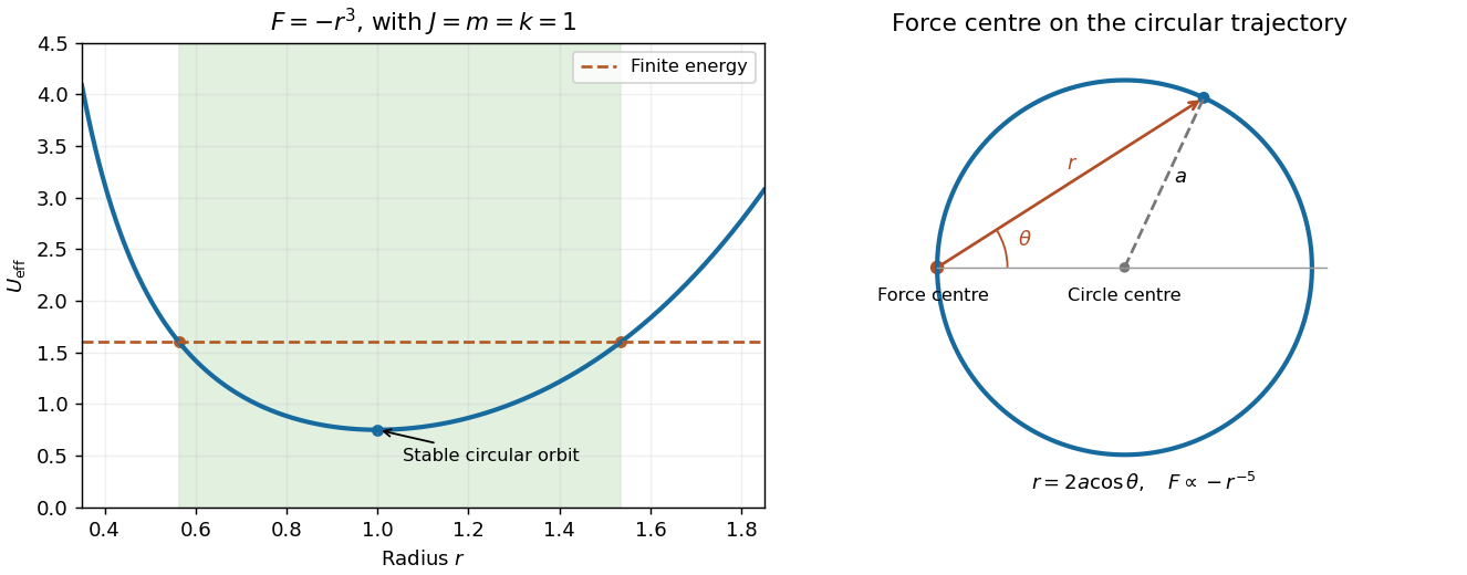
Bounded radial motion for an attractive cubic force and the distinct offset-circle geometry produced by an inverse-fifth-power force
. Details. 
For a Lagrangian expressed in independent generalized coordinates, stationary action gives the Euler-Lagrange equationsIdeal constraints can either be incorporated into the independent coordinates or treated using Lagrange multipliers, as in solution.
A cyclic coordinate is absent from the Lagrangian itself: . Its conjugate momentum therefore obeys . In the rolling-wedge calculation, the cyclic horizontal translation gives conservation of the system's horizontal momentum.
A holonomic constraint can be expressed as , rather than as a genuinely nonintegrable relation among velocities. A fixed rod length is an example. Rolling along a single straight incline also gives an integrable relation with the sign convention used below; arbitrary rolling in more dimensions need not be holonomic.
Take positive uphill, positive to the right, and the cylinder's rotation positive anticlockwise. Contact with the fixed-angle surface determines its normal position; no slipping gives . These two constraints leave as the two independent coordinates of the cylinder rolling on a freely translating wedge.
The cylinder centre is at . Since the angle is constant, its squared speed is . Including the block's kinetic energy and , and dropping a constant from the potential, givesThe cyclic coordinate is . Its conserved conjugate momentum is , the total horizontal momentum. The two Euler-Lagrange equations areEliminating the accelerations, with , givesThus the cylinder rolls downhill and the wedge accelerates rightward. For , and , the ordinary fixed-incline result.
With the wedge fixed, let be the signed gap between the cylinder bottom and the surface, positive outwards. The centre height is . Retaining all three coordinates before imposing constraints givesUse the holonomic constraints and . With the convention , the Lagrange multiplier equations areThe constraint gradients identify , the normal reaction, and , the uphill static friction force. The latter supplies the rolling torque. Setting and yieldsThe static friction condition therefore becomesfor . Static friction is required to create rotation, but does not dissipate energy here because the contact point is instantaneously at rest on the fixed plane.
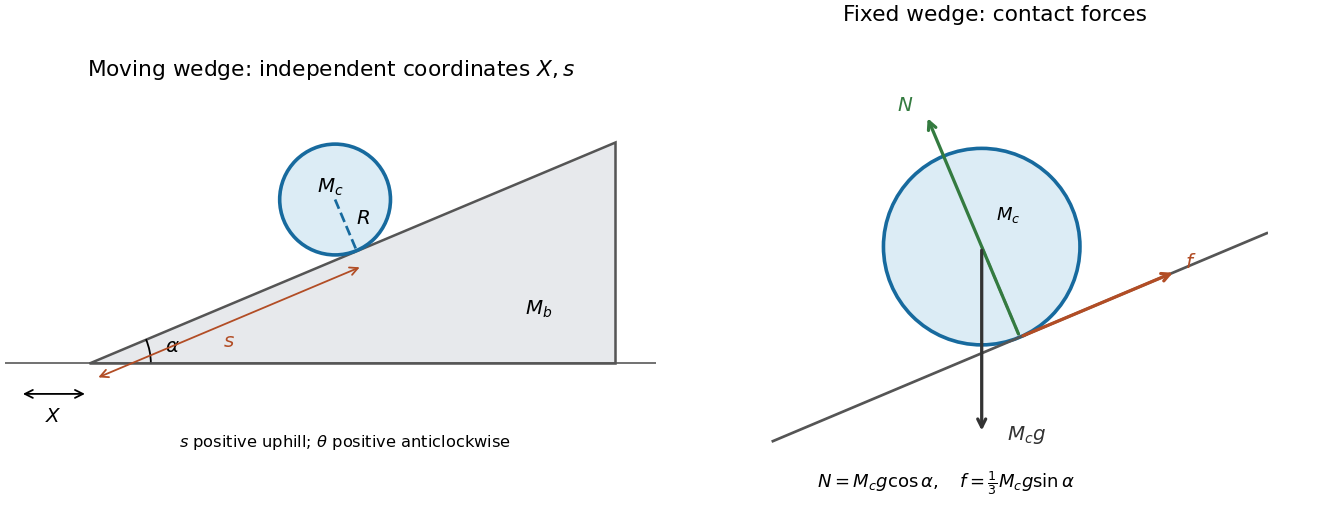
Coordinates for a rolling cylinder on a moving wedge and the normal, friction and weight forces for the fixed-wedge case
. Details. 
For a boost along at speed , the energy-momentum four-vector transforms asThe total four-vector is the sum over the particles. Write and . A centre-of-momentum rest frame exists when this total is timelike, with . Boost along and use :ThereforeThe timelike qualification is needed: exactly parallel photons alone have null total four-momentum and no such rest frame.
Use the squared total energy-momentum four-vector, expressed in energy-squared units. With the proton initially at rest,At the reaction threshold, the outgoing proton and pion have no relative kinetic energy in their centre-of-momentum frame, so . Solving givesThe numerical value uses the supplied and rest energies. The threshold exceeds the pion's rest energy because the outgoing system must carry the incident photon's nonzero laboratory momentum.
At threshold, the pion is at rest in the final centre-of-momentum frame, which moves in the laboratory withIn the pion's rest frame, its two-photon decay produces opposite photons of equal energy . The specified forward and backward directions remain collinear under this boost, soAt threshold, and . HenceThe forward photon is the more energetic one. Their product remains , as required by the invariant mass of an oppositely directed photon pair, while their sum equals the laboratory pion energy.
Articles by others on the same topic
There are currently no matching articles.