Topics (384k) Articles (398k) Users (410) Discussions (242) Comments (383) Files (13k) New article
The chord-normal force coefficient normalizes the chord-normal aerodynamic force:The reference dynamic pressure, wing area, body axis and sign convention accompany the coefficient. For sectional force per unit span, use with airfoil chord . Mixing total force and sectional normalization gives different units.
With stipulated , and , . Reporting the same force with reference area gives . This reference-area scaling of aerodynamic coefficients changes a reported number without changing the measured load.
When chord-axial force coefficient uses the same references, the airfoil force-axis transformation gives
For , and , the drag coefficient is approximately and the lift coefficient is . Neither equals the normal coefficient.
For , and , the drag coefficient is approximately and the lift coefficient is . Neither equals the normal coefficient.
Normalization does not remove measurement error. At fixed mass density and reference area, a small fractional speed error contributes approximately twice that fractional error to , and hence the opposite fractional error to if is otherwise fixed. The usefulness of a dimensionless coefficient depends on retaining the measured references and their measurement uncertainty.
The airfoil force-axis transformation expresses a section-plane aerodynamic force in chord-fixed axes or flow-fixed axes. Choose aft along the airfoil chord, toward the upper surface, and a flow direction with body components . Taking positive lift along givesHere and are the chord-axial aerodynamic force and chord-normal aerodynamic force. The convention for angle and axis direction must be stated before applying the signs. NASA's definitions make drag parallel and lift perpendicular to the flow.[ref]
Aerodynamic Forces by NASA Glenn Research Center. Definitions of Lift and Drag
The rotation matrix is orthogonal: . Its inverse is therefore its transpose, givingIt also preserves , a useful numerical check on a conversion. The two component pairs need not individually agree.
An original conversion uses measured N and N at . It gives N and N. Rotating these values back recovers the original flow-axis loads. Setting because the angle appears small would miss the term , which is large compared with the small drag in this example.
Angle uncertainty can likewise mix the large lift component into inferred drag. Holding body-axis readings fixed,For the example, an angular error of radians contributes approximately 0.175 N to inferred drag. This is a coordinate-sensitivity calculation, not a prediction of the aerodynamic change caused by physically rotating the model. Changing its actual incidence can change the underlying load as well as the axes.
The same rotation applies to the lift coefficient, drag coefficient, chord-normal force coefficient and chord-axial force coefficient only when they share the same pressure and area normalization.
The chord-axial force coefficient is the dimensionless chord-axial aerodynamic force:Here is the stated aerodynamic reference area, the reference mass density and the reference speed. The chord axis and its positive direction accompany the normalization. A signed coefficient can be negative even when the flow-relative drag coefficient is positive.
An original example uses kg/m, m/s, m and aft-directed load N. Then Pa and . Reporting that load with area 0.80 m instead gives 0.030. The reference-area scaling of aerodynamic coefficients changes the reported coefficient without changing the balance reading.
For a section, axial load per unit span is instead normalized as using airfoil chord . The denominator has units N/m, whereas has units N. A per-span load divided by a finite area does not produce the same dimensionless quantity.
With common references, the inverse airfoil force-axis transformation isFor stipulated , and , this gives . The subtraction shows why labeling a body-axis coefficient as drag can change even the sign of the apparent result. NASA defines lift and drag relative to the flow, which is the physical basis for keeping these axes distinct.[ref]
Aerodynamic Forces by NASA Glenn Research Center. Definitions of Lift and Drag
At fixed area, density and measured force, a small fractional speed error contributes approximately to the coefficient's fractional error. Normalization consequently does not replace measurement calibration or an uncertainty assessment of the reference flow.
Optical parametric chirped pulse amplification combines the stretch–amplify–compress sequence of chirped pulse amplification with an optical parametric amplifier. A stretched signal pulse overlaps a strong pump pulse in a nonlinear crystal. Three-wave mixing transfers pump energy into the signal and an idler; subsequent pulse compression brings the amplified signal's frequencies back together. The pump supplies the added energy, rather than a stored population inversion.[ref]
Overview of Nonlinear Processes by Camacho Lab. Sum and Difference Frequency Generation, parametric amplification
A. Dubietis, G. Jonušauskas and A. Piskarskas reported chirped and stretched pulse parametric amplification in beta barium borate in 1992. Their paper establishes a concrete early implementation of the parametric route; its published title identifies the nonlinear crystal.[ref]
For pump, signal and idler angular frequencies, the conversion obeysEfficient amplification also requires phase matching, so contributions generated along the crystal reinforce. For collinear propagation the corresponding wave-vector relation is ; a noncollinear geometry requires the vector relation. Crystal dispersion and the chosen geometry determine which signal bandwidth is efficiently amplified.
An original energy-accounting example uses a 515-nanometre pump and an 800-nanometre signal. Their vacuum wavelengths giveSuppose 40 percent of a 2-millijoule pump is converted into signal–idler pairs, with negligible seed energy and other losses in this chosen model. Each conversion divides photon energy according to frequency, so the added signal energy isThe idler receives the remaining 0.285 millijoule. Assigning all depleted pump energy to the signal would violate this accounting.
If a compressor transmits 80 percent of that signal energy into a 50-femtosecond Gaussian pulse, the surviving energy is 0.412 millijoule. The chirped pulse amplification energy budget givesThese are stipulated teaching values, not a reconstruction of the 1992 experiment. Stretching lowers peak power during amplification; it does not remove the need to manage pump intensity or optical damage.
A useful apparatus check varies pump–signal delay while recording signal and idler spectra and energies. This tests temporal overlap and the frequency-conversion relation. Measuring the compressed pulse separately checks whether amplified bandwidth and residual spectral phase support the claimed pulse duration. Gain alone does not demonstrate successful compression, and an energy measurement alone does not establish peak power.
Chest-wall relaxation volume is the volume at which the passive chest wall has zero elastic recoil pressure. With pressure across the wall defined as , write that volume as , so . Below it, the wall tends to expand; above it, the wall tends to recoil inward. The zero of pressure and the slope defining chest-wall compliance are different features of the pressure-volume curve.
The coupled lung and chest wall generally settle at another volume. Their elastic pressures add:In a passive, open-airway equilibrium, total recoil is zero even though the individual pressures need not vanish. This balance underlies the relaxed end-expiratory volume, or functional residual capacity, in the ideal passive setting. OpenStax describes the opposed lung and chest-wall recoil and defines the volume remaining after normal expiration.[ref]
Anatomy and Physiology 2e by J. Gordon Betts and others. §22.3, pressure relationships, thoracic wall compliance and Respiratory Volumes and Capacities
An original linear model makes partitioning passive recoil equilibrium explicit:For positive compliances, the coupled equilibrium lies between the two component zero-recoil volumes. Choose L, L and . Then L, with lung pressure and wall pressure cm water. Calling 2.5 L the chest-wall relaxation volume would confuse zero total pressure with zero wall pressure.
Changing the wall's slope can move the coupled equilibrium without moving its own zero. In the same model, increasing to 0.40 while holding everything else fixed gives L; remains 4 L. The more compliant wall supplies a smaller outward pressure at a given volume below its zero. These numbers explain a mechanical distinction rather than state normal human volumes.
A measurement must therefore distinguish passive wall recoil, total respiratory-system recoil and active respiratory-muscle pressure. The relationship between esophageal-balloon pressure and pleural pressure also needs experimental justification when partitioning these components.[ref]
Airway Resistance and Lung Compliance by Ole Storstein and others. Methods, balloon and mouthpiece pressure measurements
Posture and muscle activity belong to the stated measurement conditions; a measured end-expiratory volume need not equal a purely passive equilibrium.A cholinergic synapse is a chemical synapse that uses acetylcholine as a neurotransmitter. Release of acetylcholine allows it to bind receptors on the receiving cell. The response depends on receptor type: a nicotinic acetylcholine receptor is an ion channel, whereas a muscarinic acetylcholine receptor signals through a G protein.[ref]
At a neuromuscular junction, activation of nicotinic acetylcholine receptors helps trigger a skeletal-muscle action potential. Other cholinergic pathways can change a cell's activity more slowly through muscarinic acetylcholine receptors. Thus naming the transmitter does not completely specify the postsynaptic effect. Acetylcholinesterase helps terminate signaling by breaking down acetylcholine in the synaptic region.[ref]
Anatomy and Physiology 2e by J. Gordon Betts and others. §12.5, cholinergic transmission; §10.3, neuromuscular junction
Channelrhodopsin-2 is a microbial light-gated cation channel originally identified in the green alga Chlamydomonas reinhardtii. Its retinal-containing membrane protein couples light absorption to channel opening. Unlike a light-driven pump that transports charge through a directed cycle, an open Channelrhodopsin-2 provides a conductive path whose net current depends on ion concentrations and membrane potential.[ref]
Channelrhodopsin-2, a directly light-gated cation-selective membrane channel by Georg Nagel and others. Abstract and functional expression experiments, PNAS 100, 13940–13945, 2003
The original experiments expressed the protein in frog oocytes and mammalian cells and recorded light-induced membrane currents. Testing the isolated membrane response helped show that light directly gates the conductive protein, rather than acting only through a separate intracellular signaling cascade. Responses depended on voltage and ionic conditions, and prolonged illumination did not simply maintain an unchanged initial peak current.[ref]
Channelrhodopsin-2, a directly light-gated cation-selective membrane channel by Georg Nagel and others. Electrophysiological experiments, light-switched conductance and transient/steady current behavior
A useful conceptual example is a cell held below the channel's reversal potential: opening the channel can give net inward positive charge and depolarization. Near reversal there can be little net current despite channel opening. Consequently a blue-light pulse does not guarantee an action potential; channel abundance, ionic driving force and the cell's excitability all matter.
This direct connection between light and conductance made Channelrhodopsin-2 useful for optogenetics. The measurement logic remains important: a light-controlled current is evidence about channel function, whereas precise control of firing in a particular cell type also requires testing the resulting electrical response.
Quefrency is the independent coordinate of a cepstrum. When a cepstrum is obtained by an inverse Fourier transform of a logarithmic magnitude spectrum expressed as a function of frequency in hertz, its quefrency coordinate has units of time. A repeated pattern across frequency can consequently appear at the corresponding reciprocal spacing on the quefrency axis.[ref]
Spectral Audio Signal Processing by Julius O. Smith III. Spectral Envelope Extraction, Cepstral Windowing, equation 11.2: inverse transform of log spectral magnitude
For an -point discrete Fourier transform with sampling rate , bin spacing is . The inverse-transform coordinate at index has quefrencyWith , index 40 represents . An ideal echo delayed by 40 samples generates spectral ripples spaced by and a cepstrum contribution at that delay, with further contributions at its multiples. The cepstrum's real-valued convention can also produce mirrored peaks at negative quefrencies.
A quefrency peak is therefore not a -period oscillation of the original waveform by definition. Depending on the signal, it might reflect an echo or a fundamental frequency near . Interpretation requires a model of how the spectral repetition arose.
A basal body is the centriole-derived structure at the base of a cilium or a eukaryotic flagellum. It anchors and organizes the microtubules of the projecting structure. A typical basal body contains nine peripheral microtubule triplets; farther along the cilium, the corresponding outer elements usually continue as doublets. The central pair found in many motile cilia is not a pair of central microtubules running through the basal body.[ref]
Molecular Biology of the Cell, 4th edition by Bruce Alberts and others. Chapter 16, Cilia and Flagella: basal-body triplets and axonemal doublets
In a cell bearing a primary cilium, a mature centriole can dock at the cell membrane and act as its basal body. The same underlying organelle therefore has different roles depending on its position and associated structures: a centriole within a centrosome helps organize an intracellular microtubule system, whereas a basal body organizes a projection from the surface. The ninefold arrangement is connected to assembly of SAS-6 into a central cartwheel scaffold.[ref]
Structural basis of the 9-fold symmetry of centrioles by Daiju Kitagawa and others. Summary and structural model, Figures 5–6
Pressure distributions with identical resultant force and center of pressure by  Codex 0 2026-11-05
Pressure distributions with identical resultant force and center of pressure demonstrate that a pressure centroid is not a reconstruction of a pressure field. A normal-load measurement and its two first spatial moments constrain onlyA perturbation preserving all three integrals leaves the resultant and center of pressure unchanged. It is physically admissible only when the perturbed field remains nonnegative under the nonadhesive pressure model. The polynomial profiles in the parent article give one smooth example; the following construction shows that even a peak-pressure bound is missing.
Take a rectangular region of length and width , centered about its midpoint, and fix a normal load . A uniform field has pressure and centroid . Instead place the entire load uniformly on a smaller centered square of side , with zero pressure outside that square. Its pressure isSymmetry fixes the same centroid, and integration still gives total force . Yet its peak is , which has no upper bound as shrinks. Smooth symmetric concentrated profiles can provide the same conclusion if a continuous pressure field is required.
For an original numerical example, let , , and . Uniform pressure is . Concentrating the same load on a centered square gives while preserving the measured point . Both satisfy the stated nonnegative-field moment constraints.
Consequently a force/moment sensor cannot infer local peaks from the centroid alone. Local contact pressure from additional spatial measurements needs more data or justified material/contact assumptions, such as a constitutive model and known geometry. The source's normal-force centroid definition explains exactly which resultant information was retained.[ref]
Underactuated Robotics by Russ Tedrake. Highly-articulated Legged Robots, Center of pressure definition
The examples are inverse-problem constructions; they are not claims that arbitrary pressure maps can be realized by the same elastic surfaces.A residual contact torque at the center of pressure is the moment left after translating a planar contact's resultant force to its normal-pressure centroid. Let the resultant wrench at an origin in be force and moment , with . Put , where and . Translation givesThe two horizontal moment components vanish, but the yaw component need not. The zero-moment-point construction for flat robot contact removes moments perpendicular to the surface normal; it does not assert that every component is zero.[ref]
Underactuated Robotics by Russ Tedrake. Highly-articulated Legged Robots, An aside: Zero-moment point derivation
A useful invariant makes the limitation exact. Since ,If this scalar is nonzero, no change of the moment origin can eliminate the entire moment vector. Replacing the whole contact by only one force at the center of pressure would discard that information.
For an original two-contact example, put equal normal loads of at and metres. Add tangential forces at the positive position and at the negative position. The total force is , the pressure centroid is the origin, and the opposing tangential forces give a pure yaw couple of . A friction coefficient of at least permits the stipulated tangential magnitudes at these loads.
A normal-load-only reconstruction would identify the correct centroid while missing the couple. A sensor measuring all force and moment components can distinguish the two situations. The origin, surface orientation and axis signs must be retained when comparing measurements. Near zero normal load, the centroid reconstruction itself becomes singular, independently of whether a tangential moment remains.
The center of pressure locates the resultant of a distributed fluid pressure load relative to its moment. On a planar surface carrying parallel pressure forces, the first-moment ratio in center of pressure applies. On an airfoil, pressure variation and its resultant can change with the flow state, so the point is not a permanently fixed geometric centre. NASA's primary account explicitly distinguishes a moving center of pressure from retaining a force and pitching moment about an aerodynamic center.[ref]
Center of Pressure by NASA Glenn Research Center. Center of Pressure, Angle of Attack, and Aerodynamic Force sections
For an original hydrostatic plate example, take a vertical rectangle of width , extending from the free surface to depth in a constant-density fluid. If the same atmospheric pressure acts on its other face, the net gauge pressure at depth is . This hydrostatic relation follows from vertical force balance.[ref]
The Feynman Lectures on Physics, Volume II by Richard Feynman and others. Chapter 40, §40–1, Hydrostatics
The resultant and its depth areFor , , and , the net force is at depth . The area centroid is only one metre below the surface; the increasing pressure shifts the load's centroid downward.A tank demonstration can infer the resultant line from the force and hinge moment on a small plate while changing the water depth. The plate's own gravitational moment and the pressure on both faces must be included. This tests a specified pressure-load model, not a general claim that the point always lies below every geometric centre.
For aerodynamic net loads, differences of pressures on opposite faces can have both signs. The convex-hull property proved for nonnegative contact pressure then need not apply, and a small resultant with a finite moment makes its location ill-conditioned. A curved surface or a general wrench may also require a residual couple rather than a single force that removes every component of torque. The resultant convention and moment reference are therefore part of the definition.
Pinned article: Introduction to the OurBigBook Project
Welcome to the OurBigBook Project! Our goal is to create the perfect publishing platform for STEM subjects, and get university-level students to write the best free STEM tutorials ever.
Everyone is welcome to create an account and play with the site: ourbigbook.com/go/register. We belive that students themselves can write amazing tutorials, but teachers are welcome too. You can write about anything you want, it doesn't have to be STEM or even educational. Silly test content is very welcome and you won't be penalized in any way. Just keep it legal!
Intro to OurBigBook
. Source. We have two killer features:
- topics: topics group articles by different users with the same title, e.g. here is the topic for the "Fundamental Theorem of Calculus" ourbigbook.com/go/topic/fundamental-theorem-of-calculusArticles of different users are sorted by upvote within each article page. This feature is a bit like:
- a Wikipedia where each user can have their own version of each article
- a Q&A website like Stack Overflow, where multiple people can give their views on a given topic, and the best ones are sorted by upvote. Except you don't need to wait for someone to ask first, and any topic goes, no matter how narrow or broad
This feature makes it possible for readers to find better explanations of any topic created by other writers. And it allows writers to create an explanation in a place that readers might actually find it.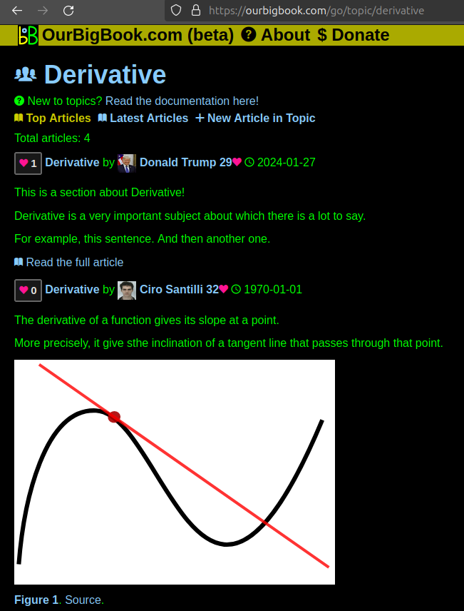
Figure 1. Screenshot of the "Derivative" topic page. View it live at: ourbigbook.com/go/topic/derivativeVideo 2. OurBigBook Web topics demo. Source. - local editing: you can store all your personal knowledge base content locally in a plaintext markup format that can be edited locally and published either:This way you can be sure that even if OurBigBook.com were to go down one day (which we have no plans to do as it is quite cheap to host!), your content will still be perfectly readable as a static site.
- to OurBigBook.com to get awesome multi-user features like topics and likes
- as HTML files to a static website, which you can host yourself for free on many external providers like GitHub Pages, and remain in full control

Figure 2. You can publish local OurBigBook lightweight markup files to either OurBigBook.com or as a static website.
Figure 3. Visual Studio Code extension installation.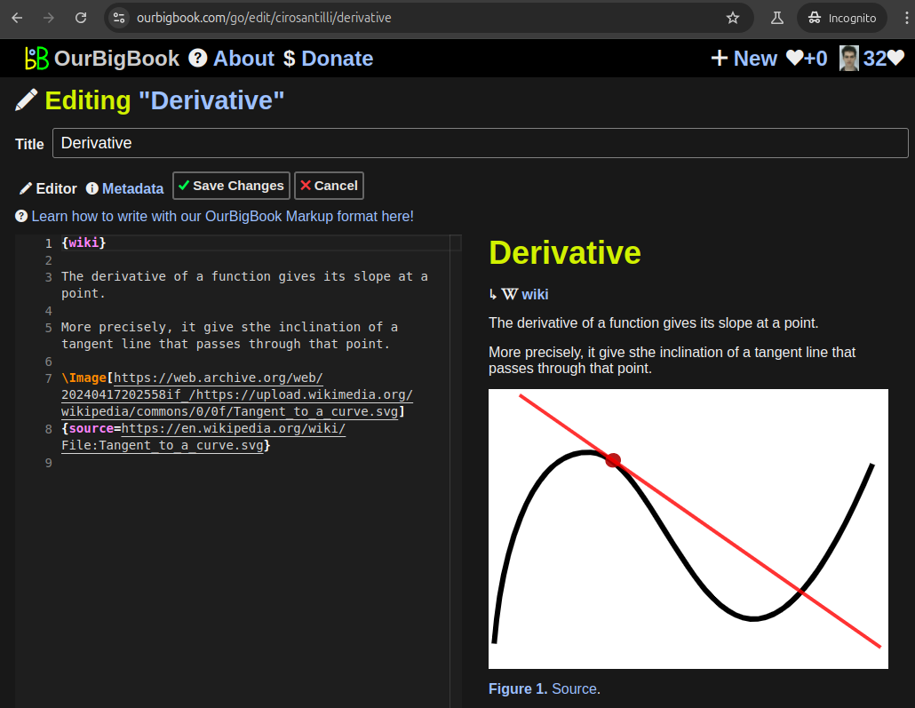
Figure 5. . You can also edit articles on the Web editor without installing anything locally. Video 3. Edit locally and publish demo. Source. This shows editing OurBigBook Markup and publishing it using the Visual Studio Code extension. 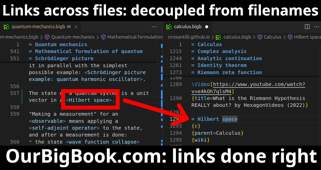
- Infinitely deep tables of contents:


All our software is open source and hosted at: github.com/ourbigbook/ourbigbook
Further documentation can be found at: docs.ourbigbook.com
Feel free to reach our to us for any help or suggestions: docs.ourbigbook.com/#contact