
A mass on a spring of stiffness , subject to linear viscous damping and a sinusoidal drive, obeys the forced harmonic oscillator equationHere is displacement, has units , and is a force in newtons. A series RLC circuit is an electrical analogue, with , , and .
- For underdamping, , the motion is , where . The amplitude decays on time and the frequency is reduced from its undamped value.
- At critical damping, , the repeated root gives . This marks the boundary between oscillatory and nonoscillatory relaxation; it is the usual fastest settling without oscillation for a release from rest.
- For overdamping, , with both roots real and negative. At large damping the slow root approaches , so increasing the resistance to motion can slow equilibration.
The constants are set by initial position and velocity. The mechanical energy and its rate of change in free motion areFor weak damping, the cycle-averaged energy decays approximately as . The quality factor is ; for it equals times stored energy divided by the loss per cycle. Logarithmic decrement of successive free-decay peaks determines experimentally.
For driven motion the complete answer is the decaying free transient plus a steady response at the driving angular frequency:At low frequency, and the displacement is nearly in phase with the drive. At , the lag is and . At high frequency, and the lag tends to . The displacement resonance maximum lies atonly when . Thus an underdamped oscillator need not have a nonzero-frequency displacement resonance peak.
In the steady state the mean input power equals the mean dissipated power:This absorption peaks exactly at , rather than at . Its half-power points have bandwidth , so for this linear model. For weak damping, a high quality factor therefore means a narrow strong resonance and a long free-decay time. Exactly zero damping at resonant driving has no finite steady response: a secular amplitude grows with time.
Past exam of the physics A course of the University of Cambridge 2022 Paper 2 Section C C8 f Solution Created 2026-10-18 Updated 2026-10-20
Keep the electron number fixed, soand . Heating smooths the Fermi-Dirac distribution across the Fermi energy, creating holes below and particles above it. The sign of the low-temperature adjustment of chemical potential follows from the local slope of the density of states.
In one dimension, decreases with energy. At fixed , smoothing removes more electrons below it than it adds above it, so initially rises. In three dimensions, increases, so falls. In two dimensions the constant density of states makes the leading changes cancel, so stays extremely close to in the degenerate regime.
For quantitative checks, a Sommerfeld expansion gives, for ,For a constant two-dimensional density of states above an unbounded parabolic band bottom, the number integral can be done exactly:soIt actually decreases, but its low-temperature correction is exponentially small rather than quadratic. “Constant in two dimensions” is therefore a low-temperature approximation, not an exact statement for every .
The one-dimensional rise is also only an initial trend. In the high-temperature Maxwell-Boltzmann distribution limit, the ideal -dimensional electron gas has , where and is the thermal de Broglie wavelength. It eventually becomes negative and decreases in every dimension. The one-dimensional chemical potential thus passes through a maximum. This high-temperature statement refers to the stipulated unbounded free-electron dispersion relation, not a claim that a real finite-width crystal band remains parabolic indefinitely.
Past exam of the physics A course of the University of Cambridge 2022 Paper 2 Section C C8 e Solution Created 2026-10-18 Updated 2026-10-20
The length, area and volume of a first Brillouin zone are . The corresponding occupied -space measures areHenceThis is state counting, independent of the interval/disk/ball geometry. One Brillouin zone contains one spatial state per unit cell in a single energy band, and that band can hold two electrons per cell because of spin. One electron per cell therefore occupies half of it. The “volume enclosed” is the occupied Fermi sea, not the lower-dimensional area of the Fermi surface itself. Its half-volume does not mean half the distance to the zone boundary in two or three dimensions.
For each primitive linear, square or cubic Bravais lattice of spacing , the reciprocal lattice has spacing . The first Brillouin zone is consequently the interval, square or cube with faces at components . The nearest zone boundary is a distance from the centre. The ratios areAll are below one: the ideal free-electron Fermi surface lies wholly inside the first Brillouin zone. Its nearest approach to the boundary is in three dimensions, where it lies only about short of the nearest face. A lattice-induced band gap at a zone face therefore does not by itself make these half-filled systems insulating in the stated free-electron model. Interactions, structural changes and actual electronic band structure can alter that model prediction.
Past exam of the physics A course of the University of Cambridge 2022 Paper 2 Section C C8 c Solution Created 2026-10-18 Updated 2026-10-20
Let and take a specimen of length, area or volume . One monovalent atom per unit cell supplieselectrons. At zero temperature, the Pauli exclusion principle fills the lowest energy states, with two spin states per spatial wavevector. The occupied region is an interval, disk or ball of radius . Using the -space density of states gives, in one dimension,In two dimensions,In three dimensions,Each Fermi energy follows from the free electron model dispersion relation . The Fermi wavevectors have units and the Fermi energies have units joules for in metres and in kilograms. No numerical lattice spacing is supplied, so numerical energies in electronvolts cannot be uniquely calculated. The spin factor of two is necessary here for actual monovalent crystals; the spinless auxiliary count of part (a) was not an instruction to remove electron spin from these crystals.
For a plane wave wavefunction , impose the cyclic or periodic boundary condition . It requiresAdjacent allowed wavenumbers on the full signed axis are spaced by . Ignoring spin, the density of states per unit is consequentlyBoth positive and negative are included in this density. It is not yet the density per unit magnitude , which has an extra factor of two away from zero. In independent dimensions the same periodic boundary conditions give one spatial state per -space cell of measure .
The required resolving power of a diffraction grating isFor illuminated slits, . In orders , the ideal resolvable wavelength differences are respectively , , and . ThusFourth order gives , only a modest margin. It must also exist: for normal incidence the grating equation requires , with needed to avoid an exactly grazing order. The relevant order must transmit appreciable light intensity rather than lie at a single-slit diffraction zero, and the source and detector widths must preserve this resolution.
The original question gives only the slit count, not the line spacing, slit width, usable diffraction order or instrumental broadening. It therefore supports the conditional conclusion “yes in fourth or higher usable order”, but not an unconditional historical claim that this particular instrument resolved the sodium absorption line doublet in its observed configuration.
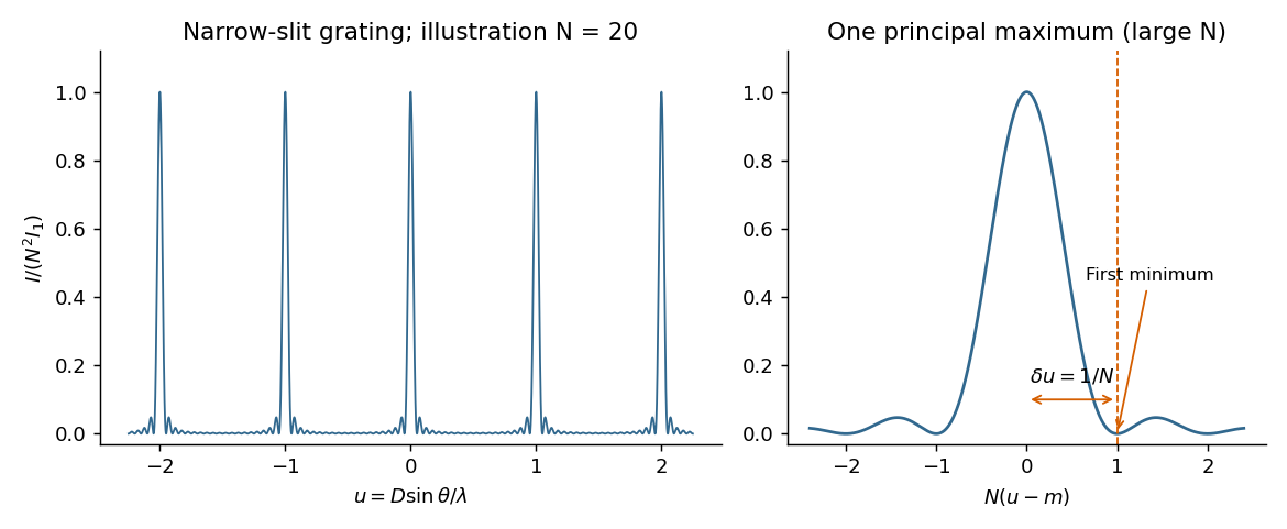
For equally spaced illuminated slits, with , summing a geometric series of complex amplitudes givesHere is the one-slit single-slit diffraction wave envelope. The grating equation for principal maxima iswith height and much weaker subsidiary maxima between orders. The first zeros around order are , so the angular distance from a maximum to its first minimum is, for large ,Changing wavelength by moves the same diffraction order byThe Rayleigh criterion places the maximum for one wavelength at the first zero for its neighbour. Equating these separations givesThis is the ideal resolving power of a diffraction grating, for an illuminated and transmitted order with sufficiently narrow source and instrumental broadening. The zeroth order has no wavelength separation and therefore no useful spectral resolving power. The distinction between and the span of the outer slit centres is a small edge convention; the exact state count in the resolving-power formula is .

The far-field complex amplitude is the two-dimensional Fourier transform of the aperture amplitude transmittance, evaluated at transverse spatial frequencies , . The light intensity is proportional to the squared magnitude of this transform.
Use linearity to add the transforms of simpler aperture components, preserving their relative phases. A translated component acquires a complex exponential factor. Repeated identical openings can be expressed as the convolution of one opening with a sum of Dirac delta functions; the convolution theorem then factors the field into a single-opening transform and an array factor. Multiplying aperture functions instead convolves their transforms. These operations simplify complex apertures without repeatedly evaluating the full diffraction integral. It is the complex amplitudes, rather than their wave intensities, that are added for coherent illumination.
For the normally incident plane wave, the incident complex amplitude and phase are uniform across the aperture. Treat the field using scalar diffraction, with the aperture represented by its prescribed amplitude transmittance . Let be the distance from the aperture centre to the observation point and let be the transverse direction cosines of that point.
Across an aperture of characteristic size , the Fraunhofer diffraction assumptions are that , so and the obliquity factor is nearly constant, and that the quadratic contribution to the propagation phase is negligible:The remaining path-length dependence is linear:A coherent monochromatic wave and an aperture large enough relative to wavelength for the scalar aperture model complete the usual physical assumptions. The complex amplitude becomeswhere includes the common propagation phase, distance factor and nearly constant obliquity factor. For the central part of a planar screen in the paraxial approximation, and . Small observation angles are useful for that screen-coordinate formula; a general far-field Fourier transform can instead use the exact direction cosines. A lens can also produce this pattern in its focal plane without requiring a physically very distant screen.
Different transverse normal modes have different cutoff frequencies and group velocities. A pulse exciting several of them reaches the output in delayed modal components, causing intermodal dispersion, pulse distortion and overlap of successive signals. Their interference also makes the transverse wave intensity pattern depend on propagation distance; irregularities can transfer energy between modes.
Mitigations are to operate between the first and second cutoff frequencies of a membrane waveguide, excite only the desired mode shape with a suitable source, and use smooth uniform boundaries or gradual transitions to reduce mode conversion. Reducing the signal bandwidth keeps its spectrum inside the single-mode interval and reduces group velocity dispersion within the selected mode. Single-mode operation removes intermodal dispersion but does not remove the dispersion derived in part (b).
The natural interpretation is the fundamental transverse normal mode, . Indeedso only propagates over the main part of the given Gaussian distribution of angular frequencies. Its centre travels atDifferentiate the group velocity with respect to angular frequency:At the centre this is . The one-standard-deviation group velocity spread is consequentlyOver the central travel time the associated spatial shear isEquivalently, use representative components at , for which and . Their separation after isAt a fixed detector away, the corresponding arrival-time difference is .
The paper asks for an estimate of spreading, without specifying a spatial width convention or the initial spectral phase. A Gaussian distribution has no finite full range. Thus is a one-standard-deviation dispersive contribution, whereas about describes the separation of the representatives. Neither is automatically the increase in the packet's original width. For an initially unchirped Gaussian wave packet in the narrow-band approximation, independent initial and dispersive contributions combine as ; a packet with an initial chirp can behave differently. The modal assumption and width convention must accompany the numerical answer.
A nondispersive wave has a linear dispersion relation over the relevant range, so every Fourier transform component has the same phase velocity and group velocity . A wave packet then translates without spreading in an ideal homogeneous lossless medium.
For wave dispersion, depends on frequency or wavenumber. Different components accumulate different phases, and in general the group velocity differs from the phase velocity; variation of group velocity across the spectrum produces spreading of a wave packet. The membrane material can be nondispersive while confinement in a membrane waveguide introduces wave dispersion along its length.
There are unlisted articles, also show them or only show them.