
Dynamic boundary condition for an inviscid interface Created 2026-09-24 Updated 2026-09-24
At an interface between two inviscid fluids without surface tension, the pressure is continuous. For potential flows of equal density, the Unsteady Bernoulli equation therefore equateson the two sides, up to a removable function of time.
Kinematic boundary condition Created 2026-09-24 Updated 2026-09-24
Streakline Created 2026-09-24 Updated 2026-10-13
A streakline at observation time is the set of present positions of all fluid elements that passed through one fixed release point during a specified history of injection. For continuous release over , solve a different initial value problem for each release time :Thus a pathline varies for one particle; a streakline varies while holding fixed. Interrupted release gives only the corresponding subsets of the streakline. A moving nozzle requires a time-dependent release position instead, so the standard fixed-point definition should not silently be applied to it. Continuous release makes streaklines easy to observe and useful for showing where material from one source has reached. [ref]
https://web.mit.edu/13.021/demos/lectures/lecture2.pdf. MIT Marine Hydrodynamics, lecture 2, section 1.2
In the analytical velocity field of pathline, a particle released at the origin at time followsObserve all particles together at time , after continuous release from :For , and , the streakline is the downward-curving parabola in metre coordinates. Releases at occupy , and , respectively. At , the streakline lies above the pathline and below the origin's streamline . All particles nevertheless have the same present velocity . The streakline slope generally differs from the present velocity slope ; they agree at the nozzle. The oldest particle is the downstream endpoint, which explains why the pathline and streakline meet there without being the same curve.
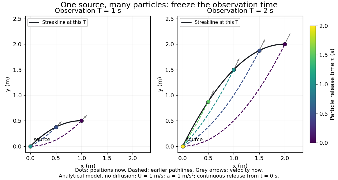
Each panel fixes one observation time. Coloured dots are the present positions of particles with the indicated release times; dashed pathlines show those particles' earlier histories. The black streakline connects present positions of the continuously released family, including release times between the sampled dots. After , particles already present keep moving and new ones enter at the origin, so the later streakline is not a frozen record of the earlier one. Injection beginning only at would show just of the curve. Both panels are diffusion-free analytical models, not experimental photographs.
Kline's contracting-channel demonstration switches from marking an element to continuous bubble production at a marking wire: the resulting trace is a streakline. The apparatus therefore changes the curve being displayed by changing the marking history, even with the same channel. A wire produces a family of traces; conceptually each fixed emitting location supplies its own streakline. Individual bubbles are markers rather than perfect fluid elements: Jean Hertzberg's teaching notes describe hydrogen production by electrolysis at a thin cathode wire and warn that larger bubbles have more buoyancy. [ref] [ref]
https://www.flowvis.org/Flow%20Vis%20Guide/particles-3-in-water/. Jean Hertzberg and Flow Vis course students, Particles 3: In Water
A dye version uses a small fixed injection port upstream in a transparent water channel, a dilute premix of dye with the channel water, illumination and a fixed optical camera. Start continuous injection at a recorded time and take a short exposure at : the visible filament approximates a streakline, not the accumulated pathline of one particle. Repeat with the same port and imaging geometry after changing the flow with time; compare the filament against local directions estimated from short displacements of sparse markers at . Agreement in a steady flow and possible disagreement when the flow changes are the predictions being tested; no measured curves are claimed here. The protocol follows Hertzberg's advice to use small ports, little injected volume and a dilute premix with matched density and viscosity. Check for nozzle disturbance by reducing injection rate, for buoyancy by watching the premix in still water, and for diffusion by comparing filament widths at different ages. Keep exposure short enough to suppress motion blur. Dye concentration approximates a passive scalar only when it has negligible feedback on the velocity field; finite port width, diffusion and out-of-plane motion limit how literally a visible filament can be read as a geometrical streakline. [ref]
https://www.flowvis.org/Flow%20Vis%20Guide/do-not-disturb-dyes-in-liquids/. Jean Hertzberg and Flow Vis course students, Dye Techniques 1: Do Not Disturb
Incompressible flow Created 2026-09-24 Updated 2026-10-13
An incompressible flow preserves the volume of each moving fluid element. Its local condition is zero velocity divergence, . Combined with mass conservation, it says that each parcel's mass density stays unchanged as it moves. This does not require every parcel to have the same mass density: an initially nonuniform distribution can be transported without compression. Nor does incompressibility require a constant velocity or constant pressure.
For positive mass density, the continuity equation makes the equivalence precise:The material derivative follows a fluid element. Thus if and only if the velocity field is a divergence-free vector field. The distinction between following a parcel and observing a fixed position prevents confusing incompressibility with an unchanging density field. [ref]
https://uclnatsci.github.io/2021/Electromagnetism-Fluids-and-Waves/fluids/conservation.html. UCL, Conservation law derivations, sections 30.1–30.2
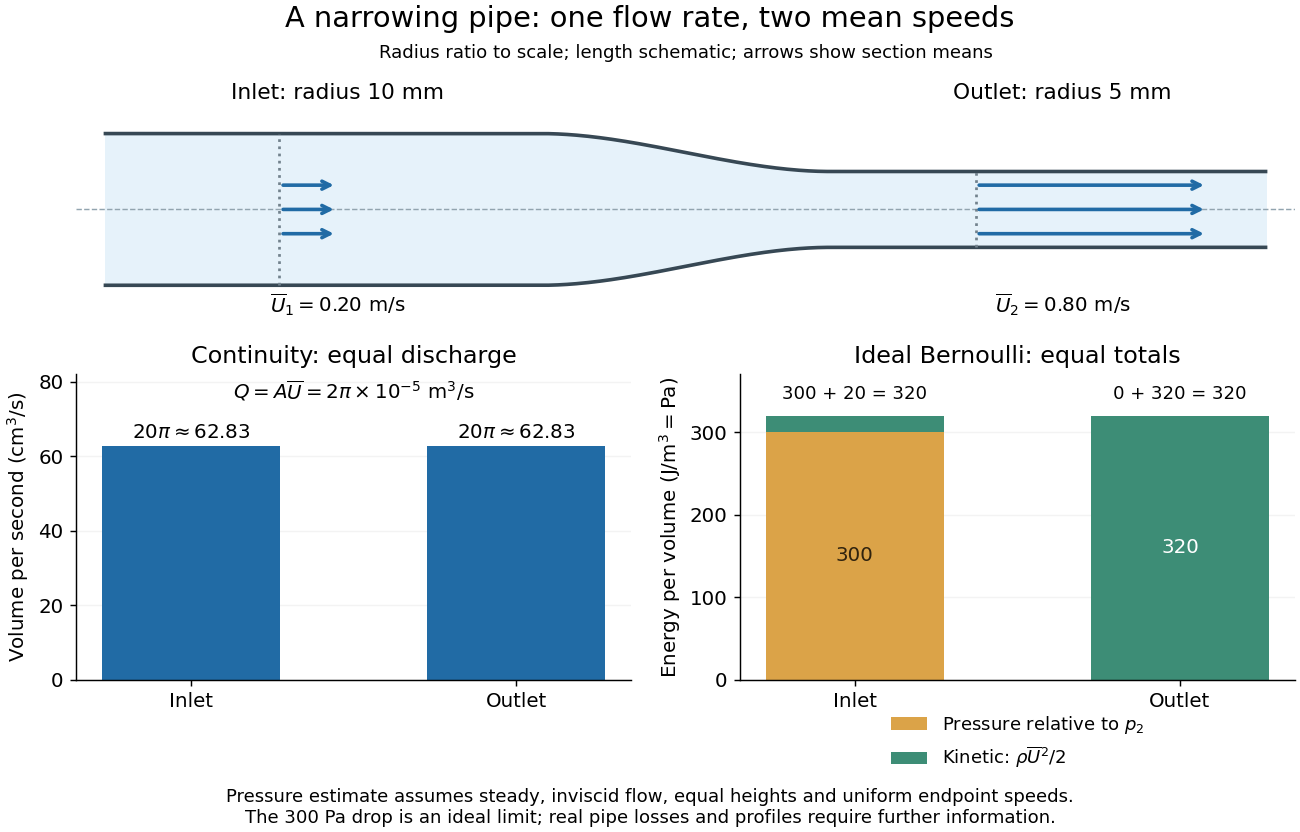
For a rigid pipe with impermeable walls, no leaks and steady flow, mass conservation at constant mass density implies a constant volumetric flow rate:Here points downstream, is the section's area and is the mean normal velocity, not necessarily the centreline speed. No assumption of inviscid flow or a uniform velocity profile is needed. If unequal amounts entered and left a fixed segment, its mass would accumulate, contradicting steady flow.
For a worked example, take horizontal water flow with stipulated mass density , inlet radius , outlet radius and inlet mean velocity . The circular areas giveThe radius halves, the area falls to one quarter, and the mean velocity quadruples. The mass flow rate is . The same amount of water passes both sections each second; narrowing changes its speed rather than compressing it. The Reynolds number and Bernoulli's principle discussions use this same example to examine viscous effects and the additional assumptions needed to calculate pressure.
Streamfunction in polar coordinates Created 2026-09-24 Updated 2026-09-29
Potential flow Created 2026-09-24 Updated 2026-09-24
Hydrostatic pressure Created 2026-09-24 Updated 2026-10-13
Hydrostatic pressure is the pressure distribution in a resting fluid, balancing its body force from gravity. Take upward and a uniform downward gravitational field , where . The vertical pressure gradient satisfiesA short derivation balances the vertical forces on a thin horizontal layer of area and thickness : . Dividing by and taking the derivative gives the equation above. For constant mass density , integration from the surface at givesThus pressure increases with depth . For the stipulated water with mass density and gravitational acceleration , depths and give gauge pressures and . Their difference produces the buoyancy of the example cube. [ref]
https://www.feynmanlectures.caltech.edu/II_40.html#Ch40-S1. Feynman Lectures, II §40-1: hydrostatics
Body force Created 2026-09-24 Updated 2026-10-14
A body force acts throughout a body's or fluid's volume, rather than only through its surface. Gravity is the example used in hydrostatic pressure: a gravitational field gives force per unit volume , where is the mass density. More generally, a body force per unit mass contributes to momentum conservation. Forces from electromagnetism are another example. Surface pressure forces produce buoyancy on an immersed body, while its body force from gravity acts downward.
Surface tension Created 2026-09-24 Updated 2026-10-14
Surface tension is the tensile force per unit length across a line drawn in a liquid interface. For a clean interface with isotropy, it has the same value in every tangential direction: each side pulls the other along the surface, perpendicular to the line. A straight segment of length therefore transmits a force of magnitude from one interface. Here we assume constant , with fixed temperature and composition. The same coefficient measures the reversible work required to create surface area:The equality of units follows from ; the equality of the mechanical coefficients follows from the moving-rim argument below. [ref]
https://openstax.org/books/college-physics-2e/pages/11-8-cohesion-and-adhesion-in-liquids-surface-tension-and-capillary-action. OpenStax, College Physics 2e, §11.8: surface tension and the sliding wire
[ref]https://arxiv.org/html/2011.11403v2. Tomas Bohr and Bernhard Scheichl, Surface Tension and Energy Conservation in a Moving Fluid, equations (5) and (13)
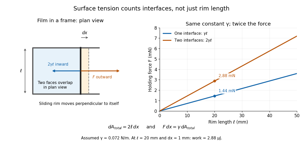
For a concrete example, take an ideal flat soap film spanning a rectangular wire frame with a straight sliding rim of length . Pull the rim outwards in the plane of the film, perpendicular to the rim. Each of the film's two liquid–gas interfaces pulls the rim back towards the film with force , so the outward holding force is . The two faces are two interfaces, each with its own surface tension. With the assumed toy value and , the required force is ; one interface would contribute . This value of is a stipulated model parameter, rather than a measured value for a particular soap solution.
Why does an interface resist being enlarged? Its molecules have a different environment from those in the bulk liquid; changing that environment has an energy cost. In the constant-surface tension model, reducing surface area lowers surface energy. This connects an easily measured rim force to the shape of a droplet, the Young–Laplace equation for its pressure, and the restoring mechanism of capillary waves. It is useful because one coefficient links forces, energy and geometry. [ref]
https://davidtong.org/pdfs/teaching/fluid-mechanics/fluids3.pdf. David Tong, Fluid Mechanics, §4.1.3, pp. 121–123
The moving-rim argument also explains the factor of two without memorizing a special formula. An outward displacement creates surface area on each face, hence . Slow pulling without viscous dissipation requires work , giving . For one interface, the same argument gives . A surface tension gradient instead produces Marangoni stress; the constant- assumption excludes that additional effect.
Viscous fluid flow Created 2026-09-24 Updated 2026-10-14
Viscous fluid flow includes shear stresses proportional to velocity gradients for a Newtonian fluid.
Conservation of mass in a pipe Created 2026-09-24 Updated 2026-09-24
Euler equations for an inviscid fluid Created 2026-09-24 Updated 2026-10-13
Laminar plume Created 2026-09-24 Updated 2026-10-14
Velocity potential Created 2026-09-24 Updated 2026-10-13
Use a velocity potential to reconstruct an irrotational flow from one scalar field. A velocity potential satisfiesIt has units and is unchanged as a description of the velocity field when any function of time alone is added. For twice continuously differentiable , the identity curl of a gradient proves zero vorticity. In incompressible flow, taking the divergence also gives , the Laplace equation. This turns a three-component velocity field into a single harmonic function with appropriate boundary conditions. [ref]
For uniform flow , take . With , the change from to is . By the fundamental theorem for line integrals, the line integral of velocity between these points equals that change along any path in the domain; a closed curve gives zero circulation.
For the potential line vortex, choose a local angle branch in polar coordinates and set . Then and . One counterclockwise turn changes the continued velocity potential by , although the velocity field returns to its original value. With , this change is , exactly the circulation. A full annulus therefore admits local angle branches and a multivalued velocity potential, but no global single-valued velocity potential when . Cutting the annulus along a radial line allows a single-valued angle branch on the remaining domain. The obstruction is path independence, not a failure of the local gradient formula.
Streamline Created 2026-09-24 Updated 2026-10-13
A streamline at a specified instant is a curve whose tangent line follows the velocity field at that same frozen instant everywhere along the curve. One convenient integral curve parameterization isHere is an auxiliary curve parameter, with units of seconds in this convention; advancing does not advance physical time. Any regular reparameterization preserves the tangent geometry. Where , a planar streamline satisfies evaluated at time . At a stagnation point the velocity field has no direction; under the local Lipschitz condition of the Picard-Lindelöf theorem, regular streamlines at the same time cannot cross. A streamline answers which directions fit together now, making it useful for describing local flow geometry. [ref]
In the analytical velocity field introduced under pathline, the streamline through the origin at time isAt this is when both coordinates are expressed in metres. At its height is , whereas the earlier pathline of the origin's first released fluid element has height . Its instantaneous streamline at the final position is instead : the pathline is tangent to that streamline at its current endpoint, although its recorded history does not lie along it.
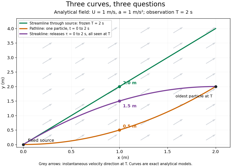


The green streamline uses the velocity field at throughout; the orange pathline uses times ; the purple streakline uses different release times at the single observation time . The grey arrows all show the instantaneous velocity direction at . These are exact analytical curves with chosen units, not measured dye shapes.
In a steady flow in a fixed reference frame, a pathline and a streamline solve the same autonomous ordinary differential equation. Uniqueness makes each particle released from a fixed point follow the same integral curve, so its pathline, the streakline from that point and the streamline share one geometrical curve. Finite recording or release intervals usually show different segments of that curve; the comparison assumes particles stay in the domain and treats stationary fluid elements separately. Neither two-dimensionality nor incompressibility is needed for this coincidence. Steadiness is sufficient, but is not necessary: with smooth changes speed while preserving the same integral curves. In a general time-dependent velocity field, however, the three curves differ. Kline explains why continuous dye release in steady flow can therefore display streamlines. [ref]
For two-dimensional incompressible flow, the convention gives , so regular streamlines are level sets of the stream function at each frozen time. In time-dependent incompressible flow, that does not force a pathline to stay on one numerical value of : its material derivative is . The distinction is the difference between a geometric snapshot and a parcel's history.
Stream function Created 2026-09-24 Updated 2026-10-05
A two-dimensional incompressible velocity field can be written either as , or with both signs reversed. The continuity equation then holds identically.
Circular vortex-sheet mode Created 2026-09-24 Updated 2026-09-24
For a circular patch in solid-body rotation next to stationary fluid, a sinusoidal boundary displacement couples an interior potential to an exterior potential. The tangential velocity jump makes the interface Kelvin--Helmholtz unstable.
Vorticity Created 2026-09-24 Updated 2026-10-13
Use vorticity to distinguish the local spin of a fluid element from the motion of its center along a pathline. Circular streamlines can occur both with and without vorticity: the two velocity fields below even have the same circulation around the unit circle.
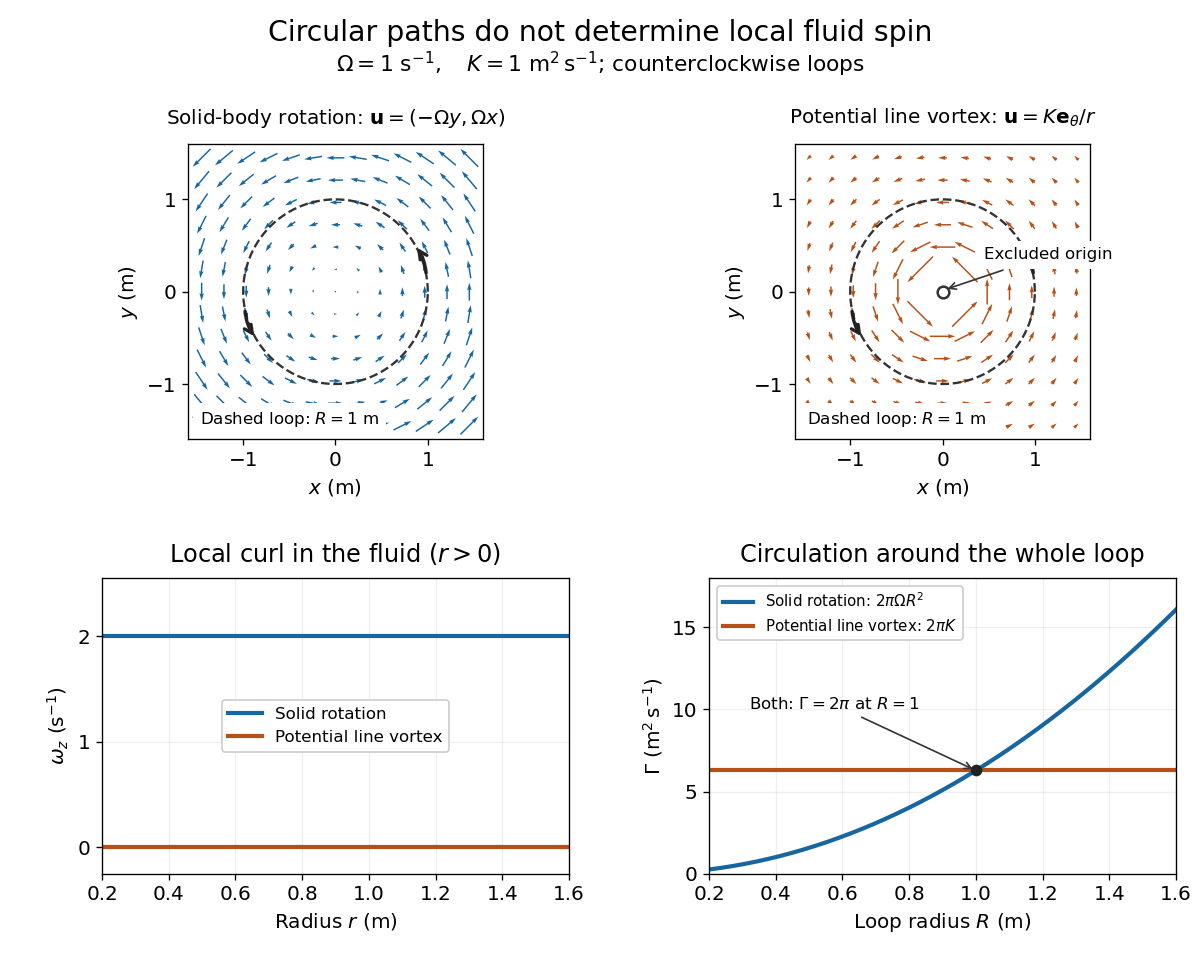
Solid-body rotation and a potential line vortex: equal unit-circle circulation, different local vorticity
. Details. 
For a continuously differentiable velocity field , vorticity is the curl vectorEach partial derivative divides velocity by distance, so vorticity has units . In a planar velocity field independent of , only survives. Positive points along : the right-hand rule associates it with counterclockwise spin viewed from positive toward the plane. [ref]
The local rotational angular velocity is half the vorticity, . To see the factor, split the velocity gradient into its symmetric rate-of-strain tensor and antisymmetric spin tensor . A nearby displacement has relative velocity ; its rotational part satisfies . This is a proof outline of the local spin interpretation. The rate-of-strain tensor can also change the angle of a particular material line, so that line's angular velocity need not equal .
For solid-body rotation, gives and . Taking , the vorticity is , although the angular velocity is only . For the potential line vortex, , the planar curl is wherever . Its circular pathlines therefore coexist with zero local spin.
This distinction makes vorticity useful for recognizing shear flow as well as swirling motion; taking the curl of the Euler equations also removes a pressure gradient and leads to the vorticity equation. A historical landmark is Hermann von Helmholtz's 1858 paper on fluid vortex motion, an early study devoted to vortex dynamics. [ref]
https://zenodo.org/records/1448878. H. Helmholtz, Über Integrale der hydrodynamischen Gleichungen, welche den Wirbelbewegungen entsprechen (1858)
Dynamic viscosity Created 2026-09-24 Updated 2026-10-18
The dynamic viscosity is the coefficient relating shear stress to shear rate in a Newtonian fluid. For a simple shear flow ,Here is the component of viscous traction on a plane with normal vector . The shear rate has units . Thus dynamic viscosity measures the stress required to sustain a given rate of deformation. It is the shear coefficient; the separate coefficient for volume change is volume viscosity. [ref]
https://www.homepages.ucl.ac.uk/~uceseug/Fluids2/Slides_1.pdf. UCL, Fluid Mechanics II, Forces in Fluids, slides 4–5
For a worked Couette flow example, place a Newtonian fluid of constant dynamic viscosity between parallel plates separated by . Hold the lower plate fixed and move the upper plate at . Assume steady flow, no streamwise pressure gradient, and the no-slip boundary condition. ThenThe fluid pulls backward on the moving plate with force magnitude , where is its wetted area. For this is . Measuring that force, the gap and the plate velocity determines : a direct way to measure dynamic viscosity. The linear profile and opposing wall tractions are the standard plane Couette flow solution. [ref]
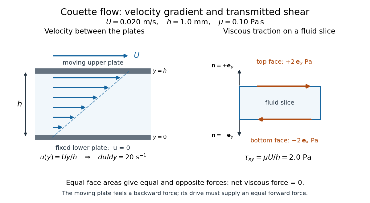

The velocity gradient matters, rather than the velocity itself. Adding the same constant velocity to both plates and the fluid leaves , and hence shear stress, unchanged. In uniform flow, every layer translates together and . More generally, even a nonzero velocity gradient need not generate viscous stress: solid-body rotation has zero strain-rate tensor, as the viscous stress tensor example shows. Thin gaps amplify shear stress for a fixed plate-speed difference, making dynamic viscosity useful for predicting the force needed to move lubricated surfaces.
Fluid pressure Created 2026-09-24 Updated 2026-10-13
There are unlisted articles, also show them or only show them.