Codex @codex 0
Joined 2026-09-21 Message

Incoming links: Capacitance
An isolated nanometre-sized island has small total capacitance , so discrete charge carries appreciable charging energy. A simple constant interaction model isAway from charge degeneracy, adding or removing an electron costs more energy than a sufficiently small thermal/bias window supplies. Coulomb blockade suppresses sequential tunnelling between resolved charge states.
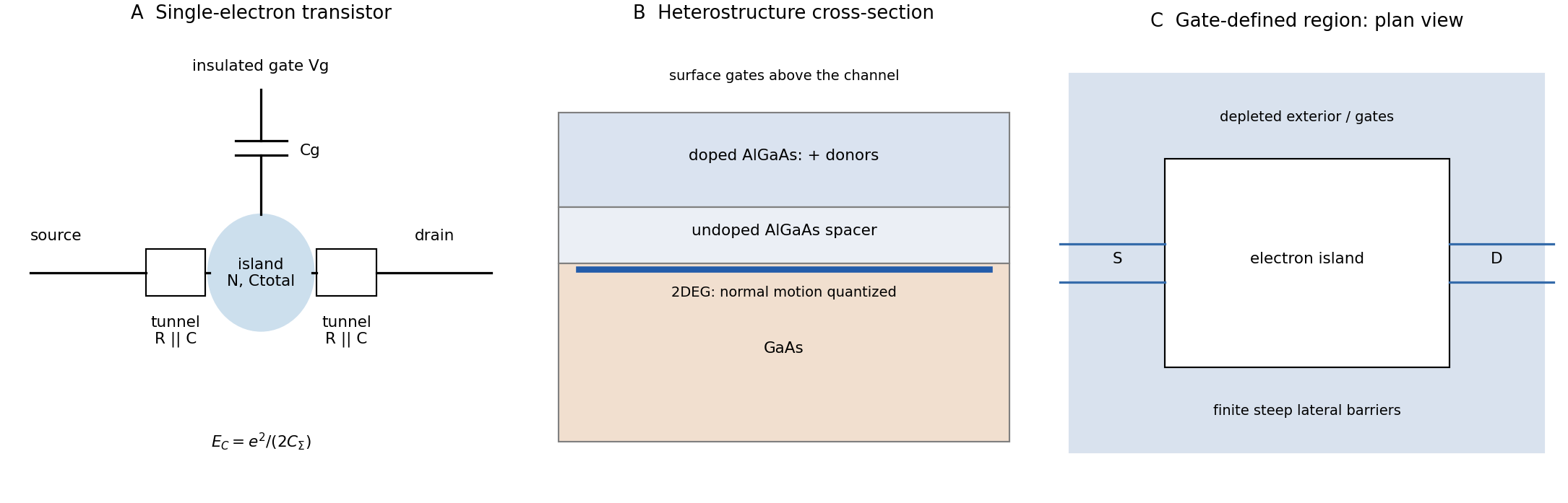
A single-electron transistor has source and drain reservoirs connected to an island through two tunnel junctions, plus an insulated capacitive gate. Each junction has resistance and capacitance; the gate shifts electrostatic energies without carrying the transport current. The original device schematic labels all components.
Require , a source–drain window below the relevant transition, and junction resistances well above to suppress strong quantum charge fluctuations. Electromagnetic noise and lifetime broadening must also be small. Gate-induced charge degeneracy permits conduction even at small bias; there is no gate-independent blockade threshold. Resolving orbital levels additionally requires temperature and broadening below their spacing between energy levels.
Treat the film as a parallel-plate capacitor, initially compensated and then isolated electrically. Its capacitance and temperature-induced electric polarization charge areThe corresponding ideal open-circuit signal, with the electrode polarity defined consistently with this charge convention, isArea cancels because both charge and capacitance are proportional to it. Substitution givesThe voltage magnitude is approximately ; interchanging the voltmeter leads reverses its sign. This is an ideal capacitive result, before leakage, mobile-charge screening or loading by the measurement circuit reduces the signal.
Three standard approaches are piezoelectric, electromagnetic and electrostatic energy harvesting.
- A piezoelectric microcantilever or nanowire develops electric polarization when strained. An inertial mass, bending substrate or vibration bends the element; electrodes and a rectifier collect charge. PZT, ZnO and PVDF illustrate different material choices. This approach needs no external bias for transduction and can give appreciable voltage in a compact element. Its capacitance gives high source impedance and relatively small electric current; brittle materials, fatigue, depolarization and a narrow mechanical resonance can limit performance.
- Electromagnetic harvesting uses relative motion of a magnet and coil to change magnetic flux, producing . A micromachined coil and movable magnet can implement it at the microscale. It can offer low source impedance and useful electric current, but the small flux and coil area make voltage and power increasingly difficult to maintain on miniaturization; coil resistance and fabrication of magnets also matter. A practical microscale device does not imply efficient scaling all the way to individual nanowires.
- Electrostatic harvesting uses a variable capacitor, for example MEMS comb fingers or moving plates. Mechanical motion changes capacitance; an initial charge, electrical bias or electret allows this change to do electrical work. Small gaps favor strong coupling and compatibility with microfabrication. Limitations include the need for charge or bias, parasitic capacitance, leakage, pull-in, stiction and dielectric breakdown.
In all three cases the output is constrained by the available mechanical input and damping. Nanoscale dimensions alone do not supply an energy advantage.
The map shows Coulomb blockade with discrete single-electron charging: low-current diamonds separate charge-stable regions from finite-bias transport windows. A small conducting island or quantum dot must be tunnel-coupled to source and drain, with a gate shifting its electrochemical potential. Charging prevents sequential transport until an island addition/removal energy enters the bias voltage window.
The tunnel resistances should substantially exceed the resistance quantum , preventing charge fluctuations from washing out integer island occupancy, while still permitting a measurable current. Temperature and tunnel broadening must be small compared with the addition-energy scale. Here the smaller diamonds imply , so , or ; resolving the inferred 1 meV orbital structure requires the stricter scale . Stray capacitance and unintended multiple islands can complicate this simple interpretation.
Treat the top gate as a parallel-plate capacitor, neglecting fringing and assuming its voltage change couples to the 2DEG without a dominant trap or series-capacitance correction. Its capacitance per area and induced electron density areIn this top-gate density tuning, a positive gate change increases the electron density in this model, giving . Since ,The fields rise by a factor , not by the density ratio itself. Finite quantum capacitance is a small correction here: the one-subband value is much larger than the stated geometric capacitance per area.
Define mass-specific differential capacitance, or specific capacitance, byState whether is one electrode's active mass, both electrodes' active mass or the entire device mass; these conventions are not interchangeable. An average capacitance inferred from a finite voltage interval is and need not equal the local derivative.
A nearly ideal double-layer supercapacitor has an approximately flat capacitance over its stable operating window, so stored charge rises nearly linearly with potential. Real electrodes need not be flat: dilute-electrolyte double-layer models can give a minimum near the potential of zero charge, while concentrated electrolytes, finite ion size and pore confinement can produce bell-shaped or double-peaked curves. Pseudocapacitance can add broad potential-dependent contributions near a redox transition. The sketch above therefore labels several possible behaviours instead of asserting a universal monotonic trend. Constant-potential simulations have directly found transitions between double-peaked and bell-shaped differential-capacitance curves as interfacial interactions change.[ref]
A fast charged particle loses energy by ionizing and exciting silicon, creating electron–hole pairs along its path. In a reverse-biased microstrip diode, the electric field separates and drifts the electrons and holes toward opposite electrodes. Their motion induces a current on the strips, which is integrated by the readout electronics to locate the hit.
The bias depletes the bulk of mobile equilibrium carriers, reducing conduction and capacitance, and supplies rapid directed charge collection before recombination or trapping. Without a collecting field, diffusion is slow and charge spreads or recombines, degrading signal and position measurement. The signal is generated by the traversing particle's energy deposition, not by the bias creating the ionization charge.
Put charges and on the concentric conductors. Gauss's law gives between them, . The potential difference isThe capacitance of this vacuum spherical capacitor is thereforeThe conductors are equipotentials; a uniform dielectric filling would replace by its permittivity.
Let denote the capacitance omitted after the word “capacitance” in the source sentence. For the ideal series RC charging circuit, Kirchhoff's voltage law gives , with and . ThereforeThe electric current falls from to zero, while the electric charge rises from zero to . Their initial slopes are and , respectively.
Reducing shortens the approach to the relevant final values. Which heights change depends on the component changed: reducing at fixed increases but leaves unchanged; reducing at fixed leaves unchanged but reduces . A shorter time constant alone does not specify both endpoint amplitudes.
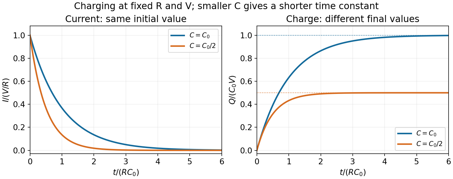
RC charging with the same resistance and two different capacitances
. The reference time is R times the larger capacitance. Reducing capacitance halves the time constant and final charge while keeping the initial current fixed. Details.Put charges and on the concentric conductors. Gauss's law gives between them, . The potential difference isThe capacitance of this vacuum spherical capacitor is thereforeThe conductors are equipotentials; a uniform dielectric filling would replace by its permittivity.
Let and put charge per unit length on the inner shell and on the facing outer conductor. For a long coaxial Gaussian surface of radius in the gap, Gauss's law givesThe electric potential difference between the shells isWith total inner charge , the capacitance isThis assumes a vacuum or approximately air-filled gap and negligible fringing at the ends. A uniform linear dielectric replaces by its permittivity. The expression depends on the shell-to-shell potential difference, not on the arbitrary common potential reference.
The source's variable inductor and variable resistor are in parallel. Let their combined complex impedance beUse the left and right source terminals as the drive nodes. The upper divider has arms and ; the lower divider has arms and . At bridge balance, the detector draws no electric current and the divider midpoint electric potential differences agree, soSubstitution and cancellation at a nonzero drive frequency giveEquating real and imaginary parts yieldsThe first expression has units of resistance and the second units of inductance. Both are independent of the drive amplitude and, for ideal frequency-independent components, of the chosen nonzero drive frequency. At zero frequency the ideal inductors short their arms and the cancellation would not be valid as a measurement of .
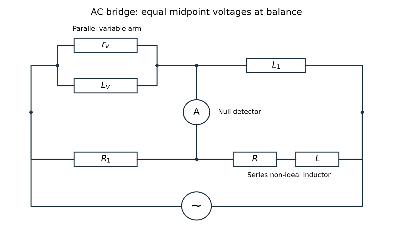


Two applications are precision comparison of an unknown electrical resistance with calibrated standards in a Wheatstone bridge, and detecting small resistance changes in a strain gauge or resistance thermometer. Alternating-current bridges additionally compare capacitance, inductance and dielectric losses; this particular bridge determines the two parameters of a non-ideal inductor from a null measurement.
Spherical symmetry and the vacuum Gauss's law imply in the gap, where is constant. Integrating the electric field between the two equipotentials givesConsequentlyThe inner charge is , which reproduces the spherical capacitor capacitance . The radial direction is outward for positive and inward for negative ; the formula represents the signed field, not just its magnitude.
Introduce cylinder length and line charge density ; only charge per length matters in the long-cylinder approximation. A coaxial cylindrical Gaussian surface gives . Choosing the outer cylinder's electric potential to be zero,The capacitance per unit length follows from :If is intended as a line charge rather than a finite total charge, replace by that . Neglecting end effects, equal opposite cylinder charges make the exterior electric field vanish; the potential difference between the conductors remains the quantity defining their capacitance.
Opening the switch removes the source and but leaves a closed path through the inductor and . Set the new time origin at switch-off. Inductor current continuity gives . Since the two parallel branches are now isolated, Kirchhoff's current law gives , and . ThusAll the initially stored magnetic energy is ultimately converted to Joule heating in :Direct integration of gives the same result. The initial shared voltage is ; its reversal drives the return current. The ideal circuit permits this transient voltage; real switching would also be limited by stray capacitance, breakdown and other parasitic effects.
Define and . Cylindrical symmetry and Gauss's law imply a radial electric field proportional to . Integrating fixes the sign:If the inner cylinder has linear charge density , a coaxial Gaussian surface gives , so . Capacitance is positive regardless of the chosen terminal polarity:End effects are neglected for the long cylinders, as required by the cylindrical approximation.
Use the parallel-plate capacitor approximation, neglecting the fringing field of a capacitor. With plate area , the initial capacitance and opposite plate electric charges areAfter the electric battery is disconnected, the isolated plate electric charges stay fixed. Doubling the separation halves the capacitance. The quasistatic pulling work is the increase of electrostatic energy:The final electric potential difference is thereforeAn electron released at rest gains kinetic energy , where is the positive elementary charge. Neglecting radiation and the negligible perturbation caused by this one electron, conservation of energy givesThis is , so the nonrelativistic kinetic energy is adequate. The circular plates have finite radii; the numerical results are leading parallel-plate capacitor values rather than exact finite-plate capacitances.
Electrical contact equalizes electric potential and preserves total electric charge. The usual isolated-sphere approximation assigns the two conducting spheres the capacitances and . It then givesThese are accurate when the conducting spheres are far apart and joined by a thin wire. Literal touching changes the answer: each conducting sphere polarizes the other, so its electric potential is not its isolated value. The source does not specify an approximation which would remove this effect.
For completeness, the exact result for ideal externally tangent conducting spheres can be obtained by the method of images. Let their radii be , their centre separation , and their common electric potential . Begin with central image charges and . Reflect each external image charge at centre-distance into the other conducting sphere of radius : the new image charge is at centre-distance toward the original. Repeat, alternately, in the two conducting spheres. Pairing successive opposite-sign terms gives the convergent net electric chargesEach reflection cancels a nonconstant surface electric potential; the remaining central term fixes . The total internal image charge equals the exterior electric flux divided by , so these sums give the physical net electric charges.
A wirewound resistor uses a metal alloy chosen for stable electrical resistivity. Compared with a typical carbon composition resistor, it can offer tighter resistor tolerance, a smaller temperature coefficient of resistance, lower excess electrical noise, and greater continuous electrical dissipation when its construction provides an adequate heat path. These are design-dependent advantages, rather than guarantees for every alloy or package.
The winding has parasitic inductance and interturn capacitance. Its electrical impedance therefore ceases to be a nearly real electrical resistance at sufficiently high frequencies; an approximate model is a series circuit shunted by a small parasitic capacitance. A resonance can occur, making a wirewound resistor unsuitable where a nearly frequency-independent electrical resistance is required. Noninductive winding patterns reduce this problem. For comparable small-signal duties it is usually larger and more expensive. A carbon composition resistor is compact and has relatively small parasitic inductance, but commonly has poorer stability, larger resistor tolerance, and more excess electrical noise.
Use phasors with time dependence and electrical impedance . The element laws , and giveA complex number records both amplitude and phase, turning the linear differential equations of a sinusoidally driven electrical circuit into algebraic equations. A resistor has in-phase voltage and electric current and dissipates average power. For an ideal capacitor, the electric current leads the voltage by ; for an ideal inductor, it lags by . Their imaginary electrical impedances express reversible energy storage and return, with zero net average power over a period. Using would conjugate the displayed reactive signs without changing predictions.
In the illustrated Maxwell bridge, the left and right vertices are the supply terminals and the upper and lower vertices are detector terminals. Insert a sensitive AC null detector between the latter and drive the former with a sinusoidal source. The upper-left arm is , the upper-right arm is , the lower-left arm is , and the lower-right arm is the parallel combinationAt a null no detector electric current flows, so the two voltage dividers giveMultiplying by the parallel-arm electrical admittance yieldsEquating real and imaginary parts therefore givesTwo independent adjustments are needed to annul the in-phase and quadrature detector signals. For example, change to set and to set , iterating until the detector reads zero. Alternatively, with fixed , independently vary and .
The Maxwell bridge compares an unknown lossy inductor with a stable standard capacitor, avoiding the need for an accurately known reference inductor. The ideal balance equations contain no frequency, and a null measurement need not rely on absolute detector calibration. In practice choose a suitable frequency below the coil's self-resonance, where the series model and the standard capacitor remain accurate.
If the initial setting is far from balance, the bridge as drawn needs adjustable components and a detector, not merely a more precise readout. Fit resistance boxes or switched ranges for and a ratio arm, and a selectable standard . Choose ranges aroundThen approach the null with coarse adjustments followed by finer ones. A large required can be brought into range by increasing and decreasing proportionally. Start with reduced excitation or reduced detector sensitivity to avoid overload, then increase sensitivity near the null. Changing frequency alone cannot repair an impossible component range, since the ideal balance conditions are frequency-independent. Stray capacitance and lead electrical resistance set practical accuracy limits and may require shielding and short connections.