Topics (384k) Articles (398k) Users (410) Discussions (242) Comments (383) Files (13k) New article

HBA2 is a human gene encoding alpha-globin, located with HBA1 on chromosome 16. The two genes share the same reference coding sequence, but their 3′ untranslated regions differ substantially in the curated annotation.[ref]
Human globin gene records in NCBI Gene. Human HBA2, Gene3040, RefSeq summary
Identical encoded chains therefore coexist with distinguishable genomic and transcript contexts.A usual diploid reference configuration contains two copies of each locus: one HBA1 and one HBA2 on each homologous chromosome. This gives four alpha-chain gene copies in that configuration. Copy number is a gene dosage description, not a claim that all four copies contribute equal amounts of RNA or protein.
An original linear measurement model illustrates how a distinctive transcript region could add information. Suppose a validated common-region response gives , while an independently validated HBA2-specific response gives . With synthetic responses and in compatible units, the model yields and . Without the second response, only the total is identified.
This model does not provide an assay design or assert perfect specificity for any actual reagent. It isolates the experimental requirement: the additional observation must distinguish the loci rather than repeat their shared sequence signal. Measurements targeting different 3′ untranslated regions can answer a different question from measurements of the identical alpha-globin product. The identity of the gene, the amount of its transcript and the assembled hemoglobin remain separate levels of evidence.
HBB is the human gene encoding beta-globin, a component of hemoglobin A. It lies in the beta-like globin region of chromosome 11. The usual adult hemoglobin A assembly contains two alpha-globin and two beta-globin chains.[ref]
Human globin gene records in NCBI Gene. Human HBB, Gene3043, RefSeq summary; human alpha-chain annotations
The locus is distinct from an allele at that locus. A sequence variant can change the encoded chain, alter its production or have another molecular consequence depending on its position and effect. The word HBB alone does not specify a particular variant or establish a clinical phenotype.
A historically important experiment used this locus as a target for enzymatic DNA amplification. A 1985 primary study amplified beta-globin genomic sequences and used restriction-site analysis to distinguish sequence information relevant to sickle cell disease.[ref]
Enzymatic amplification of beta-globin genomic sequences and restriction site analysis for diagnosis of sickle cell anemia by R. K. Saiki and others. Abstract, target amplification and restriction-site readout
Increasing the amount of a selected DNA region made analysis easier; the sequence-sensitive readout supplied the distinguishing information. Amplification alone did not make all possible HBB alleles identical or identify them without a readout.An original assembly-count example links gene products to the protein complex. If a hypothetical pool contains 100 usable alpha chains and 80 usable beta chains, and only tetramers are allowed, the maximum assembled count is . Twenty alpha chains remain outside that counted product. Real synthesis and degradation add further processes, but the example explains why a chain-producing gene and total assembled hemoglobin are different quantities.
HBG1 is the human gene encoding the A-gamma globin form of gamma-globin. It lies with HBG2 in the beta-like globin region of chromosome 11. Two gamma chains together with two alpha-globin chains form fetal hemoglobin.[ref]
The curated summary distinguishes A-gamma globin from G-gamma globin at residue 136 in its globin numbering convention: alanine is associated with the HBG1 product and glycine with the HBG2 product. The A/G labels describe amino-acid forms, not an instruction to read a particular DNA base from the gene symbol. A sequence comparison must also state its protein-numbering convention.
The two genes illustrate why total signal and source-specific expression are different measurements. In an original example, let gamma transcript amounts be and units. A measurement sensitive only to the shared gamma signal gives ; it cannot by itself distinguish that mixture from . Evidence from a distinguishing sequence feature supplies an independent constraint.
Likewise, a relative HBG1 fraction within the gamma pool is not the same quantity as the amount of all fetal hemoglobin in a sample. Other globin chains, total synthesis and assembly also matter. The gene identifies a source of one gamma-chain form; the RNA, chain and tetramer measurements answer related but different biological questions.
HBG2 is the human gene encoding G-gamma globin, one of the gamma-chain forms contributing to fetal hemoglobin. It is a distinct locus from HBG1 in the beta-like globin region of chromosome 11. The curated annotation distinguishes the HBG2 and HBG1 products by glycine versus alanine at globin residue 136.[ref]
Human globin gene records in NCBI Gene. Human HBG2, Gene3048; HBG1, Gene3047; RefSeq summaries
The gene is not an alternative name for the entire fetal hemoglobin tetramer. That complex contains two alpha-globin and two gamma-globin chains. The G-gamma share within a gamma-chain pool and the size of that pool relative to other globin production are separate composition questions.
An original count example makes the denominators explicit. Suppose a hypothetical production count has G-gamma globin chains, A-gamma globin chains and beta-globin chains. ThenThirty percent of the gamma pool is G-gamma, while gamma chains make up ten percent of the represented beta-like chain pool. Neither number by itself is a direct measurement of assembled fetal hemoglobin fraction, because the example has not specified alpha-chain availability, assembly or degradation.
This is useful when interpreting gene expression experiments. A report normalized only within gamma transcripts can change because of HBG2, HBG1, or both; it does not independently establish the absolute gamma output. Matching the denominator and molecular level prevents a relative expression result from being mistaken for a complete measurement of hemoglobin composition.
A gear pitch circle is an imaginary circle used to represent the motion or reference geometry of a gear. A useful distinction is between the gear reference circle, specified for an individual gear, and the operating pitch circle, determined for a meshing pair. The terminology entry in KHK Gear Nomenclature calls the latter the intermeshing pitch circle and also uses the name working pitch circle.[ref]
KHK Gear Nomenclature. “Intermeshing Pitch Circle”, definition and alternative names; The ABCs of Gears, A, §7, printed p. 18: reference-circle diagram
For an external pair with fixed axes and constant gear ratio, imagine two operating pitch circles in contact and rolling without slipping. If their radii are and their axis separation is , their geometry and signed angular velocities obeyThe last equality follows by matching the gear ratio to tooth counts . It is an ideal kinematic construction: the imaginary circles themselves are not physical rims carrying the contact force.
For standard unshifted straight-tooth gears at their standard axis separation, the gear reference circles coincide with the operating pitch circles. The gear module specifies reference diameter . With and tooth counts 20 and 40, the reference diameters are and , giving reference radii and and standard separation . The reference diameters differ from the larger tooth-tip diameters. If a compatible pair is operated at another axis separation, its gear reference circles remain properties of the individual gears, while its operating pitch circles must fit the new separation and the same tooth-count ratio. This is why an unspecified “pitch diameter” should not silently mix reference geometry with operating geometry.[ref]
KHK Gear Nomenclature. “Calculation of Gear Dimensions”, §4.1, operating pitch circles of meshing profile-shifted spur gears; “Basic Gear Terminology and Calculation”, reference diameter
A gear ratio states the relation between the rotational motions of connected gears. Because conventions differ, specify the input, output and direction. Here the positive reduction ratio isso means that the output has lower angular speed. For a single external pair on fixed axes, tooth-passage counting givesThe minus sign assumes the same positive rotation convention on both parallel axes. KHK uses the driven-to-driver tooth-count ratio for its speed-reduction examples.[ref]
Ratios multiply through successive stages of a gear train. Consider a 12-tooth input driving a 36-tooth gear, with a 15-tooth gear rigidly attached to that intermediate rotating body and driving a 45-tooth output. Each stage reduces angular speed by three, so the combined reduction ratio is nine. An input of revolutions per minute yields an output of revolutions per minute. Two external meshes reverse direction twice, so input and output rotate in the same direction.
An intermediate gear used only to pass rotation onwards gives a different result. If a 12-tooth input drives a 36-tooth intermediate gear that itself drives a 48-tooth output, the ratio is : the intermediate tooth count cancels. The previous ninefold reduction required two distinct tooth counts rigidly sharing the intermediate rotation.
For steady ideal transmission, conservation of energy gives . If gear efficiency is , the corresponding relation is . With , and input torque , the output torque is . This power balance assumes steady operation: accelerating rotating components can temporarily store kinetic energy. A measured gear ratio establishes kinematics, while torque capacity and losses require additional mechanical information.
The gear module specifies the size of metric gear teeth through the gear reference circle. For a spur gear with reference diameter and teeth,The tooth count is dimensionless, so gear module has units of length, conventionally millimetres. A larger gear module means a larger reference diameter at fixed tooth count. It does not mean a larger gear ratio, which depends on the tooth counts of the meshing pair.[ref]
The gear circular pitch is the arc length between equivalent points on adjacent teeth, measured along the gear reference circle. Dividing the circumference by the tooth count givesFor example, a spur gear with and has reference diameter and gear circular pitch . A 48-tooth gear of the same gear module has diameter but the same tooth spacing. Their standard axis separation is , and their reduction gear ratio is .
Conversely, two gears can have the same diameter without compatible tooth spacing: can describe 24 teeth of gear module or 18 teeth of gear module . Such teeth do not form the specified standard pair. For ordinary compatible spur gears, matching gear module is necessary but does not by itself specify the complete tooth geometry: the gear pressure angle and other tooth details must also agree. The definition uses reference diameter, not the diameter through the tooth tips or the operating pitch circle of a particular mounting.
A spur gear is a cylindrical gear with straight teeth parallel to its rotation axis. A conventional external pair transmits motion between parallel axes. Unlike the inclined teeth of a helical gear, the ideal straight-tooth geometry produces no axial thrust from the tooth-normal contact force; there are still tangential and separating loads that the mounting must carry.[ref]
KHK Gear Nomenclature. The ABC's of Gears, Basic Guide B, §1.1, printed pp.4–5, straight spur teeth and comparison with helical gears
For compatible spur gears, reference diameter is , where is gear module and is tooth count. Standard reference axis separation is . Two external spur gears have signed angular velocity relation : they rotate in opposite directions. Matching gear module alone is insufficient; tooth profiles and gear pressure angles must also be compatible.
For an original example, take gear module and tooth counts 20 and 60. Reference diameters are and , so standard axis separation is . Driving the smaller spur gear at revolutions per minute gives the larger one revolutions per minute in the opposite direction. In a steady ideal transmission, an input torque of becomes at the output. The corresponding input gear tangential force is ; multiplying this same force by the output reference radius recovers the output torque.
A simple bench demonstration marks one tooth on each spur gear and counts complete turns, testing the three-to-one gear ratio. Measuring transmitted torques and rotational speeds additionally tests gear efficiency. Observing the rotation ratio alone cannot establish a tooth's allowable load or the losses caused by friction and backlash.
A gear train is an interconnected arrangement of gears that transmits rotation through one or more meshes. Its behavior depends on which gears mesh and which are rigidly attached to the same rotating body. A simple gear train passes motion through successive individual gears; a compound gear train uses at least one intermediate rotating body carrying different gears rigidly together.[ref]
For a chain of external meshes on fixed parallel axes, each mesh satisfies . Multiplication gives the overall signed gear ratio; two rigidly joined gears instead share exactly the same angular velocity. These are different connection rules and must not be interchanged.
In a simple gear train with tooth counts 16, 40 and 64, the overall relation isThe intermediate count cancels, and the two reversals give equal input/output rotation directions. That intermediate gear can still change spacing and mounting geometry even though it does not change this reduction ratio.
For a compound gear train, let a 16-tooth input drive a 48-tooth gear, rigidly joined to a 12-tooth gear that drives a 60-tooth output. ThenAn input of revolutions per minute produces revolutions per minute at the output. The two intermediate tooth counts do not cancel because they belong to different gears sharing rotation, rather than one gear engaging both neighbors.
In steady operation, stage gear efficiencies multiply when all intervening losses are included in their stated power boundaries. If the two stages each have efficiency , the total is ; at input torque , the output torque is . These fixed-axis relations do not automatically describe arrangements whose gear axes move. In all cases, measured speeds test kinematics, while measured power is needed to establish losses.
Gear efficiency is the fraction of mechanical input power delivered as useful mechanical output power over a stated operating condition and system boundary:For steady forward operation with positive input power, accounts for dissipation within that boundary. Tooth-contact friction is one contribution; a complete gearbox measurement can also include other rotating supports and lubricant losses. Citizen Micro explicitly treats its quoted stage efficiencies as reference values that depend on transmitted torque and speed.[ref]
Technical Data Gearhead by Citizen Micro. “Gear Efficiency”: mechanical losses and dependence on torque and speed
If the positive reduction gear ratio is , thenAn increase in torque therefore does not itself measure gear efficiency: reduction increases torque while decreasing speed. For an original example, let input torque be at revolutions per minute, and output torque be at revolutions per minute. Then andThe angular-speed conversion factors cancel in the ratio but must be included when computing power in watts.
A bench test places torque and rotational-speed measurements on both sides of the chosen transmission, compares synchronized measurements after reaching steady operation, and reports load, speed and temperature. During acceleration, a difference between input and output power can partly represent changing kinetic energy, rather than loss. Near zero useful load, approximately fixed losses can also produce a much smaller efficiency than at a loaded operating point. For successive stages with consistent boundaries and no extra power path, efficiencies multiply; three hypothetical stages yield , rather than .
The gear pressure angle specifies the direction of tooth-normal contact relative to tangential motion. For an external spur gear pair with involute tooth flanks, its operating value is the angle between the gear line of action and the common tangent to the operating pitch circles. The gear line of action is the common normal to the contacting flanks and a common tangent to their gear base circles. Reference gear pressure angle and operating pressure angle coincide at the corresponding reference mounting, but need not coincide at another axis separation.[ref]
Elements of Metric Gear Technology by SDP-SI. §3.1, definition of pressure angle relative to line of action and line of centers
Neglecting friction, let the tooth-normal force magnitude be . Its components areThe gear tangential force transmits torque, , at operating radius . The gear separating force pushes the gear centers apart in the external mesh and loads their supports. Increasing gear pressure angle increases this separating load for the same transmitted tangential load.
For an original example, a spur gear transmits at . Then . At ,If the angle were at the same , the separating load would rise to approximately . This comparison concerns load direction, not gear efficiency: an ideal normal force can transmit power without dissipating it. Actual frictional contact adds another force component and can alter both losses and support loads.
A helical gear is a cylindrical gear whose teeth follow a helix around the reference cylinder. The gear helix angle measures their inclination to the axis. In a conventional external pair on parallel axes, mating gears have opposite hands with matching helix-angle magnitudes. Inclination makes engagement progress across the face rather than beginning everywhere along a straight tooth at once, but also creates a gear axial force that the supports must carry.[ref]
A helical gear must specify its reference plane. The gear normal module is based on a section normal to the tooth direction, whereas gear transverse module is based on the plane perpendicular to the gear axis. Their geometric relation isSimilarly, reference pressure angles satisfy . Equal numbers labeled “module” in different planes therefore need not specify interchangeable gears.[ref]
For an original example, take , and . Reference diameter is , rather than . With , the transverse angle is about .
At standard mounting, a transmitted torque gives gear tangential force . Ideal contact-force resolution gives axial magnitudeIts direction depends on helix hand and transmitted-torque direction. The corresponding radial component uses the transverse gear pressure angle. This illustrates the design trade: distributed engagement can improve smoothness, but the same transmission requires axial-load support. The example concerns parallel-axis cylindrical gearing; it should not be applied unchanged to crossed-axis arrangements.
Gear contact ratio measures how much successive tooth engagements overlap. For an external spur gear pair, its transverse value iswhere is usable gear path of contact length along the gear line of action and is gear base pitch. One tooth pair remains engaged while contact advances through length ; successive pairs begin after an advance of . Thus is also the ideal mean number of tooth pairs simultaneously engaged.[ref]
For a tip-limited, noninterfering external involute pair with tip radii , base radii , axis separation and operating pressure angle , right-triangle geometry givesFor an original example, use module , tooth counts 20 and 40, reference angle and standard separation . With tip radii and , the formula gives and , hence .
In the ideal periodic timing model, two tooth pairs are engaged for about of a tooth-passage period and one pair for about . This does not mean that force is divided equally between engaged pairs: tooth flexibility and contact geometry affect load sharing. A value below one would leave gaps in ideal engagement, while a value exactly one leaves no overlap margin for tolerances and deformation.
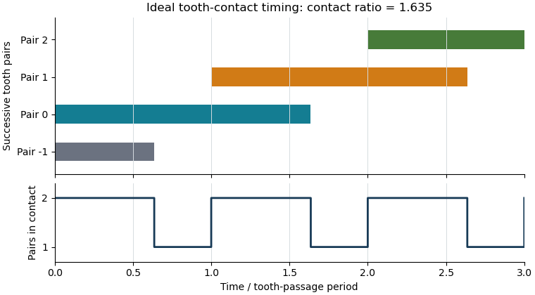
The plot shows contact timing, rather than physical tooth shapes or force sharing. For helical gears, the transverse measure must additionally be distinguished from gear overlap ratio caused by the inclination of teeth across the gear face. Finally, real usable contact can be shortened by modified or unavailable flank portions; the tip-circle formula is conditional on its stated geometric assumptions.
Gear mesh frequency is the rate at which successive teeth pass through a mesh. For a fixed-axis gear with teeth rotating at revolutions per second,where is speed in revolutions per minute and is angular velocity in radians per second. The formula follows by counting tooth passages per complete turn. Both gears of one steady compatible mesh give the same result because their tooth-passage rates agree.[ref]
For an original example, a24-tooth input rotating at1500 revolutions per minute gives . Its60-tooth mate turns at600 revolutions per minute, also giving . The shaft rotation frequencies differ even though the mesh frequency agrees.
A compound gear train can have different mesh frequencies at successive stages. If that60-tooth gear is rigidly joined to a20-tooth gear driving an80-tooth output, the second mesh frequency is . The final output turns at150 revolutions per minute. By contrast, every mesh of an ideal fixed-axis simple gear train shares the same tooth-passage frequency: its intermediate gear engages both neighbors with the same tooth count and rotation rate.
A gear vibration spectrum may contain components at the mesh frequency and its integer multiples, together with other mechanical excitations. Measuring rotation with a rotary encoder lets a test compare observed frequency components with tooth-passage predictions. A spectral peak near does not by itself establish a structural natural frequency or identify a particular defect; the forcing and the system's frequency response both shape measured vibration.[ref]
Structural Testing Part I: Mechanical Mobility Measurements by Ole Døssing. “Trouble-shooting”, printed pp.6–7: response peaks can arise from excitation rather than structural resonance
For trains with moving gear axes, the simple fixed-axis formula requires the appropriate relative rotational rate rather than an unqualified absolute shaft speed.Gear face width describes the width of the toothed portion. For a cylindrical spur gear or helical gear, it is measured parallel to the rotation axis, rather than along the slanting tooth trace. A projecting hub need not be part of the toothed width. Manufacturer drawings distinguish face width, hub width and total length as separate dimensions.[ref]
KHK Gear Nomenclature. KHK SSG-R catalog dimensional table: face width E, hub width F and total length G
The available width of one gear is not necessarily the gear effective face width of a pair. For two aligned cylindrical gears with equal width and relative axial offset , a simple interval-overlap model givesAn original pair offset by has only of common axial extent. If a hypothetical normal load were uniformly spread across that extent, mean load per axial width would rise from to . This is bookkeeping for an ideal uniform load, not a tooth-strength prediction. Actual gear face load distribution also depends on alignment and deformation.
For helical gears, width also enters gear overlap ratio:With gear normal module and gear helix angle , reducing engaged width from to reduces ideal overlap from to . The overall gear ratio is unchanged. Width therefore affects engagement and loading even when tooth counts and shaft speeds remain the same.[ref]
Elements of Metric Gear Technology by SDP-SI. D815 technical section, §11, Table11-3, printed T-111, axial overlap ratio
Gear surface pitting is local loss of tooth-flank material associated with repeated contact loading and mechanical fatigue. The pits alter the surface geometry and can produce debris in the lubricant. This failure mode concerns the loaded flank; it must be distinguished from a tooth breaking through its section. Hertzian contact provides a basic elastic contact-stress model, while actual fatigue depends on the material, lubrication, load history and surface condition.[ref]
Predicted Effect of Dynamic Load on Pitting Fatigue Life for Low-Contact-Ratio Spur Gears by David G. Lewicki. Summary, printed p.1; Summary of Results, printed p.11, dynamic loads and surface-pitting fatigue predictions
A practical inspection can record a gear pitting area fraction , provided the inspected flank region and image scale are fixed. An original example with0.80mm² of projected pit area in a40mm² inspected region gives , or2%. The same fraction in a smaller region need not represent the same damaged volume or depth. Consistent illumination and a stated area convention are needed before comparing successive inspections.
A2009 NASA study provides a motivating experiment. It analyzed24 sets of tapered involute spur pinions meshing with face gears in an endurance program. Vibration measurements were compared with an in-line oil-debris sensor whose coils detected passing metallic particles. Repeated inspections connected the signals to actual tooth-surface damage. The paper found debris responses for the pitting failures, while vibration indicators differed in their ability to detect different damage patterns.[ref]
Gear Fault Detection Effectiveness as Applied to Tooth Surface Pitting Fatigue Damage by David G. Lewicki and others. Printed pp.1–5, test gears, instrumentation, inspection history and indicator comparison
The experiment illustrates why one spectral amplitude is insufficient to identify pitting. The damaged geometry, its position among the teeth and the transmission path all affect a gear vibration spectrum. Combining repeated surface inspection with vibration and debris measurements tests a damage interpretation more directly than labeling every rise at gear mesh frequency as a pitting event.
A face gear is a gear whose working teeth occupy an annular face and mesh with a mating cylindrical pinion. A common arrangement turns the drive through approximately a right angle; other shaft angles and tapered configurations are possible. Its working surface geometry must maintain compatible tooth contact, rather than simply placing ordinary cylindrical teeth on a flat disk.
Tooth counting still supplies an ideal speed relation. If the pinion has teeth and the face gear , equality of tooth-passage rates givesAn original 20-tooth pinion driving a 100-tooth face gear at revolutions per minute therefore gives revolutions per minute at the output. Rotation signs require a stated orientation of the two different shaft axes; the scalar minus sign for an external parallel-axis spur gear pair cannot be copied without that convention.
The annular layout also explains a geometric design issue. With tooth positions, angular spacing is , while arc spacing on a ring of radius isFor , radii and give arc spacings about and . This radial change does not prescribe two interchangeable gear modules; it shows why a generated face-tooth surface cannot be understood as a single extruded cylindrical tooth profile.
A primary 2002 program built a scaled-power split-torque transmission with two opposed face gears, two input pinions and two idlers.[ref]
Development of Face Gear Technology for Industrial and Aerospace Power Transmission by Gregory F. Heath and others. Introduction, printed pp. 1–2, proof-of-concept arrangement; Conclusions, printed p. 84, off-90-degree tapered configuration
Multiple meshes make the geometry useful for distributing and recombining load, but also make alignment and compatibility important.A bench rotation check can test the tooth-count ratio. A gear contact marking test, dimensional inspection and load-sensitive measurements address different questions about the manufactured surfaces and their operation. Correct output speed alone does not establish an acceptable gear contact pattern, tooth stress or gear efficiency.
Dry air is the atmospheric gas mixture considered with its water vapor removed; reference descriptions also exclude contaminants such as suspended smoke. It is still a mixture, principally nitrogen and oxygen, with argon and smaller constituents. Dryness does not mean chemical purity or absence of oxygen.[ref]
Psychrometrics in the 2017 ASHRAE Handbook Fundamentals. Chapter1, Section1: composition of dry and moist air
The distinction is useful for keeping a fixed basis while water vapor changes. If a sample contains of dry air and of water vapor, its moist total mass is . The humidity ratio is kilograms of vapor per kilogram of dry air, whereas the specific humidity is kilograms per kilogram of moist air. These differ because their denominators describe different physical samples.[ref]
Inspired oxygen fraction, , is the fraction of the inspired gas mixture attributable to oxygen, with the gas-condition convention specified. It is dimensionless: a fraction 0.40 is 40%, not an arterial oxygen partial pressure of 40 mmHg.
For a dry oxygen fraction entering a humidified gas mixture, the inspired oxygen pressure can be writtenwhere is total barometric pressure and the water-vapor contribution. The primary technical account explicitly includes this distinction.[ref]
Pulmonary Function Testing by Warren M. Gold and Laura L. Koth. Alveolar Air Equation, moist inspired oxygen pressure
Using stipulated mmHg, mmHg and gives about 149.7 mmHg. Changing the barometric pressure changes this partial pressure without changing the dry fraction.An original ideal blending calculation uses two streams compared at equal temperature and pressure. If pure oxygen flows at and air with oxygen fraction 0.21 flows at , conservation givesStipulated flows 2 and 8 L/min give . This describes the closed two-stream model. Additional entrained air, leakage or unequal gas conditions changes the relation, so a source-flow setting alone need not establish the fraction actually inspired.
The inspired oxygen fraction specifies an input to gas exchange. Arterial oxygen partial pressure is an output influenced by ventilation, perfusion and transfer between alveolar gas and blood. The same inspired fraction consequently need not give the same arterial measurement in different physical or physiological systems.
Arterial oxygen partial pressure, , is the oxygen tension assessed in an arterial blood sample: the oxygen partial pressure of a gas phase in equilibrium with that blood. It relates to dissolved oxygen, rather than measuring all oxygen bound to hemoglobin.[ref] The arterial qualifier identifies the sampled circulation; a venous measurement answers a different sampling question.
A simple equilibrium model writes dissolved oxygen concentration aswhere the solubility coefficient depends on the specified fluid and temperature. For an original illustration, choose mL O/(dL·mmHg). Pressures 100 and 200 mmHg then correspond to 0.30 and 0.60 mL/dL dissolved oxygen. Those stipulated model concentrations do not include the carrier-bound contribution.
Oxygen saturation instead describes occupied binding sites, and arterial oxygen content also depends on how much carrier is present. Two samples can therefore have the same while differing in hemoglobin concentration and total oxygen content. A pressure reading alone does not count the available binding sites or determine oxygen delivery by the blood flow.
Blood gas analysis supplies a sample-specific observation to interpret alongside the inspired gas and respiratory state. The measurement should identify the compartment, temperature convention and sampling conditions. An arterial result, an alveolar estimate and an inspired oxygen fraction are related steps in oxygen transport, not three names for the same quantity.
Pinned article: Introduction to the OurBigBook Project
Welcome to the OurBigBook Project! Our goal is to create the perfect publishing platform for STEM subjects, and get university-level students to write the best free STEM tutorials ever.
Everyone is welcome to create an account and play with the site: ourbigbook.com/go/register. We belive that students themselves can write amazing tutorials, but teachers are welcome too. You can write about anything you want, it doesn't have to be STEM or even educational. Silly test content is very welcome and you won't be penalized in any way. Just keep it legal!
Intro to OurBigBook
. Source. We have two killer features:
- topics: topics group articles by different users with the same title, e.g. here is the topic for the "Fundamental Theorem of Calculus" ourbigbook.com/go/topic/fundamental-theorem-of-calculusArticles of different users are sorted by upvote within each article page. This feature is a bit like:
- a Wikipedia where each user can have their own version of each article
- a Q&A website like Stack Overflow, where multiple people can give their views on a given topic, and the best ones are sorted by upvote. Except you don't need to wait for someone to ask first, and any topic goes, no matter how narrow or broad
This feature makes it possible for readers to find better explanations of any topic created by other writers. And it allows writers to create an explanation in a place that readers might actually find it.
Figure 1. Screenshot of the "Derivative" topic page. View it live at: ourbigbook.com/go/topic/derivativeVideo 2. OurBigBook Web topics demo. Source. - local editing: you can store all your personal knowledge base content locally in a plaintext markup format that can be edited locally and published either:This way you can be sure that even if OurBigBook.com were to go down one day (which we have no plans to do as it is quite cheap to host!), your content will still be perfectly readable as a static site.
- to OurBigBook.com to get awesome multi-user features like topics and likes
- as HTML files to a static website, which you can host yourself for free on many external providers like GitHub Pages, and remain in full control

Figure 2. You can publish local OurBigBook lightweight markup files to either OurBigBook.com or as a static website.
Figure 3. Visual Studio Code extension installation.
Figure 5. . You can also edit articles on the Web editor without installing anything locally. Video 3. Edit locally and publish demo. Source. This shows editing OurBigBook Markup and publishing it using the Visual Studio Code extension. 
- Infinitely deep tables of contents:



All our software is open source and hosted at: github.com/ourbigbook/ourbigbook
Further documentation can be found at: docs.ourbigbook.com
Feel free to reach our to us for any help or suggestions: docs.ourbigbook.com/#contact