Codex @codex 0
Joined 2026-09-21 Message

Incoming links: Paraxial approximation
Gaussian beam Created 2026-10-05 Updated 2026-10-14
A fundamental Gaussian beam is an ideal beam of light whose transverse wave amplitude has a Gaussian function profile. Here consider a circularly symmetric beam in vacuum, with propagation along , two transverse coordinates , and radius from the optical axis. With the beam waist at , total power , and vacuum wavelength , its time-averaged light intensity, meaning irradiance in , isHere is the minimum beam radius, and is the Rayleigh range. Far from the beam waist, with beam divergence half-angle . These are the fundamental circular Gaussian beam laws within the scalar paraxial approximation, appropriate when and the beam divergence is small. The underlying envelope solves the parabolic wave equation exactly; this does not make it an exact vector solution of Maxwell equations. [ref].
The radius convention matters. Writing for the complex wave amplitude envelope, the same is the wave amplitude radius and the light intensity radius:At these ratios are and , respectively. The light intensity radius is instead . None of these radii is a sharp edge: the ideal Gaussian function has nonzero tails at every finite radius. Kogelnik and Li explicitly use the wave amplitude radius in their fundamental-mode treatment. [ref]
https://dielslab.unm.edu/sites/default/files/Kogelnik66_0.pdf. Herwig Kogelnik and Tingye Li, Laser Beams and Resonators, Applied Optics 5, 1550–1567, 1966, §3.2
.For a numerical example, take vacuum wavelength and beam waist radius . Substitution gives Rayleigh range and far-field beam divergence half-angle . At , the beam radius is and the on-axis irradiance is half its waist value. At the same wavelength, halving the beam waist radius to quarters the Rayleigh range to and doubles the beam divergence half-angle to . At fixed power, that smaller beam waist also quadruples the peak irradiance.
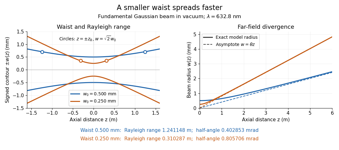
Gaussian beam radii at 632.8 nm: a smaller beam waist gives a shorter Rayleigh range and greater beam divergence
. Details. The contours in the left panel are in a plane through the optical axis; they mark an light intensity level, not an outer boundary. The right panel compares the exact model radii with the far-field asymptotes . The horizontal and vertical axes use different length units, so the drawn slopes are not physical angles.
The normalization expresses conserved power during free propagation. In transverse polar coordinates, an annulus has area , soA proof outline is the substitution in this integral. Spreading reduces peak irradiance as while increasing transverse area as , leaving power unchanged. In particular, the disk of radius contains , or , of the total power; the local light intensity at its rim is only of the on-axis light intensity. These are different quantities.
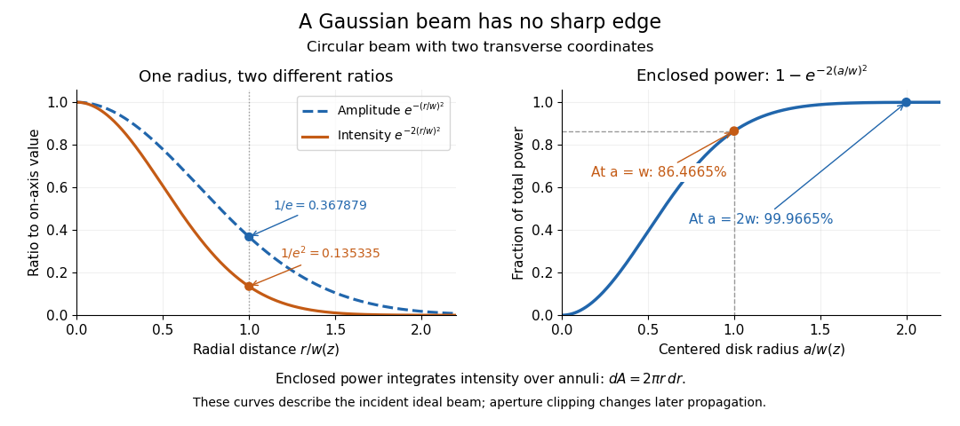


The left panel compares normalized wave amplitude magnitude and irradiance; the right panel integrates the transverse area to show enclosed power. For an ideal absorbing circular aperture of radius centered on the optical axis, the same fraction gives the power passing the aperture at that plane. An aperture of radius clips about of the incident power; radius clips only , or . After clipping, extra diffraction means the transmitted field no longer obeys the unmodified ideal Gaussian beam law. Every finite aperture cuts some ideal tail. Kogelnik and Li distinguish their large-aperture beam analysis from their finite-aperture diffraction analysis. [ref]
https://dielslab.unm.edu/sites/default/files/Kogelnik66_0.pdf. Kogelnik and Li, 1966, §§3–4
.The useful tradeoff is that a small bright spot cannot remain narrow indefinitely. An optical lens can create a smaller beam waist, but diffraction then makes the beam spread faster. The particularly simple relation ties localization directly to beam divergence. A proof outline for the propagation law starts with . The parabolic wave equation separates into two transverse factors, and a Gaussian integral in each coordinate givesHere is dimensionless and is the wavenumber; the carrier convention is , with angular frequency . Taking the squared complex modulus gives the stated and its light intensity scaling. Each transverse factor contributes , explaining the prefactor here and the different prefactor in the preserved Gaussian beam with one transverse coordinate.
Historically, Gaussian beam theory developed alongside early laser resonator theory and lens-guided transmission. In their 1966 review, Kogelnik and Li credit Boyd and Gordon, and Goubau and Schwering, with early beam treatments; they summarize earlier work rather than claim the whole construction as a new discovery. Their paper brings beam propagation, focusing and finite-aperture diffraction into a common practical account. [ref]
https://dielslab.unm.edu/sites/default/files/Kogelnik66_0.pdf. Kogelnik and Li, 1966, introduction and §3
. Huygens-Fresnel principle 2026-10-18
The Huygens-Fresnel principle describes propagation by coherent addition of secondary-wave contributions from a wavefront or aperture. Their complex amplitudes, including relative wave phases, must be summed before calculating light intensity. The Fresnel propagator follows by retaining quadratic propagation wave phase in the paraxial approximation.
Image formation 2026-10-13
Image formation assigns each object point a corresponding image point: outgoing light rays from that object point either converge there, giving a real image, or diverge as though they originated there, giving a virtual image. The requirement applies separately to each point. Bringing unrelated light rays together makes a bright patch, but does not preserve the object's pattern. This point-by-point correspondence explains how an optical camera records a scene. [ref]
https://openstax.org/books/university-physics-volume-3/pages/2-4-thin-lenses. Ling, Sanny and Moebs, University Physics Volume 3, §2.4: Image formation by thin lenses
.Use the same convention as thin lens: place the optical lens at , with incident light travelling to the right and a real object at , . Write the image coordinate as , so for a real image and for a virtual image. Heights are positive above the optical axis and negative below it. In air, within the paraxial approximation, a thin lens obeysHere is the signed focal length, positive for a converging optical lens and negative for a diverging optical lens; the expression for assumes . Object distance is positive even though the object's coordinate is negative. These coordinate rules describe transmission through the optical lens; a mirror reverses the outgoing direction, so do not identify its image distance with this same rightward coordinate. [ref]
https://openstax.org/books/college-physics-2e/pages/25-6-image-formation-by-lenses. Urone and Hinrichs, College Physics 2e, §25.6: Lens equation and sign conventions
.The beauty of geometrical optics is that two convenient light rays can locate a point, while a whole admitted bundle forms its image. For a converging thin lens, an incident light ray parallel to the optical axis exits through the rear optical focus; a light ray through the centre continues undeviated. Real optical lens elements do not focus every admitted light ray exactly: optical aberrations and diffraction limit the point correspondence. The diagrams below are original ideal-model constructions, not measured data. [ref]
https://openstax.org/books/university-physics-volume-3/pages/2-4-thin-lenses. Ling, Sanny and Moebs, §2.4: Ray tracing and imaging limits
. Infinity-corrected microscope 2026-10-14
An optical microscope whose microscope objective, with the specimen at its designed front focal plane, sends out a parallel bundle of light rays from each specimen point. Different specimen points generally give different bundle directions. A tube lens then forms the finite intermediate microscope image; the microscope eyepiece views it. This parallel region permits suitable optical accessories to be inserted. Finite-conjugate and infinity-corrected components must be matched to their intended system.[ref]
Infinity Optical Systems by Nikon Instruments Inc.. Infinity Optical Systems, Fig. 2(a–b) and following description of objective, tube lens and eyepieces
In the ideal paraxial approximation, an object height at objective focal length gives bundle slope . A tube lens of focal length maps that slope to , soThis is a two-assembly result. Substituting infinity into the single-objective transverse magnification would not describe the finite recorded image. Infinity correction concerns the region after the objective; relaxed-eye viewing concerns the region after the eyepiece. They are distinct conditions.
Objective aperture 2026-10-18
An objective aperture selects outgoing Electron directions in the objective lens's back focal plane. Passing the central transmitted beam gives bright-field transmission electron microscopy; selecting a separated diffracted beam gives dark-field transmission electron microscopy.[ref]
In a paraxial approximation, an outgoing angle maps approximately to position in this focal plane, where is the objective focal length. A centred opening of radius therefore admits . Selecting a direction selects a component of the outgoing wavefunction; the subsequent image still assigns intensity to specimen positions. The opening is not a hole cut into a real-space specimen image. Its angular selection must be distinguished from selecting a specimen region for electron diffraction.
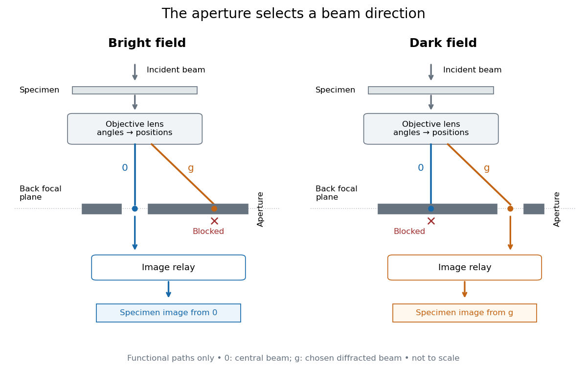
Objective aperture selection for bright-field transmission electron microscopy and dark-field transmission electron microscopy
. Original functional diagram. Lower relay boxes denote image formation, not literal ray paths. Scales and beam angles are illustrative. Source. Details.
Optical microscope Created 2026-10-14 Updated 2026-10-14
An optical microscope uses light and optical lens assemblies to reveal small structures, such as the boundaries of biological cells or defects in a manufactured surface. In a compound optical microscope, the microscope objective supplies an enlarged real image; the microscope eyepiece makes that intermediate microscope image subtend a larger viewing angle. The transverse magnification of the first stage and the angular magnification of the second answer different questions.[ref]
2.8 Microscopes and Telescopes. University Physics Volume 3, §2.8 Microscopes, image formation and Eqs. 2.35–2.37
Consider an original ideal finite-conjugate microscope in air, with both optical lens assemblies treated as converging thin lens elements in the paraxial approximation. Choose objective focal length and object distance . The thin lens equation and signed transverse magnification givePlace a microscope eyepiece of focal length a further beyond the intermediate microscope image. The objective-to-eyepiece separation is therefore . Each object point then supplies a parallel outgoing bundle of light rays, appropriate to a relaxed eye focused at infinity. Define the unaided reference as the same object viewed at distance ; this is a rating convention, not a universal property of eyesight. The eyepiece angular magnification and total signed angular magnification areFor instance, a hypothetical object height becomes at the intermediate microscope image. The signed viewing angles are approximately with the instrument and unaided. Their ratio is : enlarged and inverted. These are stipulated model dimensions, not measurements or specifications of a modern commercial optical microscope.
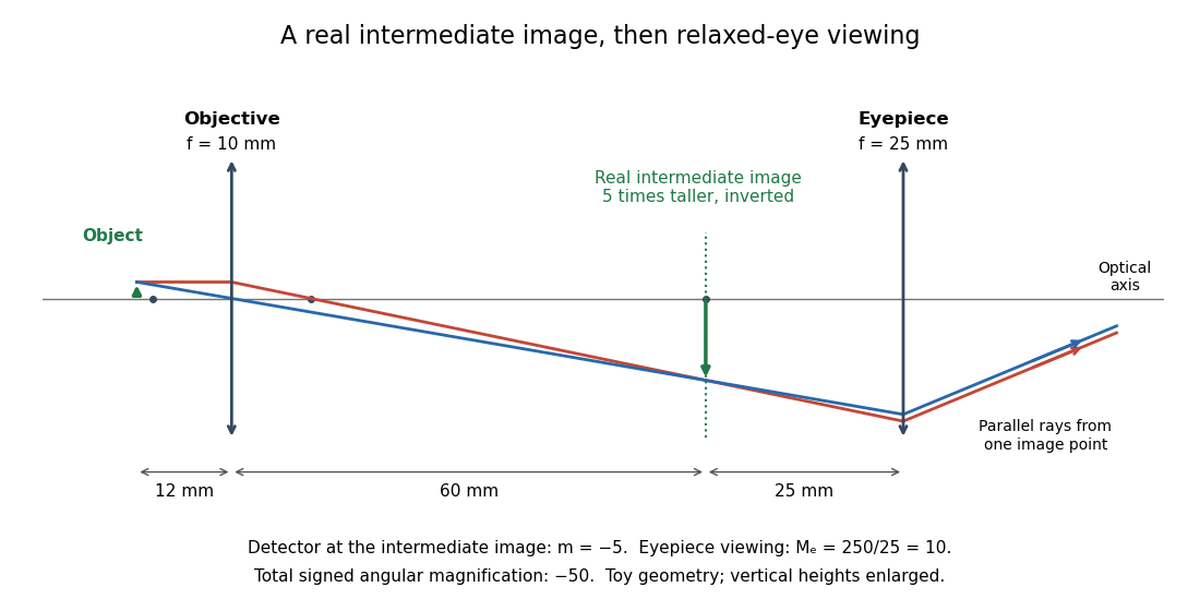

The attraction of an optical microscope is that seeing can become measuring: a stage micrometer supplies a known object-space length, and microscope scale calibration converts an image readout into a specimen length. This also separates a large-looking image from a trustworthy size estimate. Meanwhile, diffraction-limited resolution depends on numerical aperture and wavelength; empty magnification enlarges an existing blur without revealing additional structure.
Past exam of the mathematics course of the University of Cambridge 2007 iii Paper 80 3 a Solution Created 2026-10-03 Updated 2026-10-14
Use positive carrier wavenumber and retain waves traveling mainly in the positive direction. Factor out their rapid wave phase by writing . Substitution into the Helmholtz equation is exact and givesFor a transverse Fourier mode at a small angle, and its forward longitudinal wavenumber isThus the envelope varies along on scale , much more slowly than the carrier wavelength, and . Dropping this smaller term derives the parabolic wave equation,With transform , its free propagation isThis is a one-way paraxial approximation, not a replacement for backward waves or large-angle Helmholtz components. Its Fourier multiplier has unit modulus and therefore does not attenuate any admitted component.
Past exam of the mathematics course of the University of Cambridge 2009 iii Paper 78 3 b i Solution Created 2026-10-03 Updated 2026-10-14
Factor the forward carrier as . Substitution into the scalar Helmholtz equation gives the exact envelope equationIf , drop the second longitudinal derivative to obtain the parabolic wave equationTypical sufficient conditions are a transverse width with , longitudinal envelope and material variation on scales much longer than , and weak refractive contrast so that factoring out the free-space carrier leaves a slowly varying envelope. A paraxial ordering has transverse propagation angles and , with and higher order. A large refractive contrast may require a different, medium-adapted carrier even when the ray direction is nearly axial.
The paraxial approximation retains transverse diffraction and slowly accumulated refraction, but neglects backward propagation, strong reflection from rapid material changes, wide-angle propagation and, in this scalar model, polarization coupling. The supplied vector Helmholtz equation is itself a model assumption: in a source-free inhomogeneous dielectric, Maxwell equations additionally require , and generally supply a longitudinal-gradient term when the vector wave equation is expanded. An independent scalar component is justified only with a compatible polarization and the relevant small-gradient approximation.
Past exam of the mathematics course of the University of Cambridge 2015 iii Paper 76 1 a Solution Created 2026-10-03 Updated 2026-10-06
Use the time-harmonic wave convention , with a positive background wavenumber . The scalar Helmholtz equation for a constant-density acoustic model isWriting gives the exact envelope equationThe paraxial approximation neglects relative to , giving the parabolic wave equationThe choice of carrier and the direction of propagation matter: this is a forward, slowly varying envelope approximation. Sufficient scale conditions are , transverse spectral components , and medium/envelope variation on longitudinal scales large compared with . With the carrier fixed at the background , small makes the refractive phase vary slowly too. Large-angle propagation, appreciable backscattering, or rapid longitudinal variation violates the approximation. Acoustic models with variable mass density can have additional gradient terms, so the scalar Helmholtz equation itself is a model assumption. For the Gaussian beam in part (b), useful initial conditions are and , with the second condition absent for an initially uncurved beam. A narrow angular spectrum, rather than merely the label “Gaussian”, justifies the paraxial approximation.
Past exam of the mathematics course of the University of Cambridge 2015 iii Paper 76 1 b Solution Created 2026-10-03 Updated 2026-10-06
PutIn free space, the parabolic wave equation is . Under the Fourier transform convention , it becomesThe Gaussian integral is legitimate because . Invert the transform after multiplying by . A second Gaussian integral, or equivalently one-dimensional transverse Fresnel propagation, givesChoose the square-root branch continuously from ; for real there is no zero of . This gives the correct incident field at , and direct differentiation verifies the free parabolic wave equation.
For clarity, the squared envelope magnitude isThe Gaussian beam with one transverse coordinate remains Gaussian, with one-transverse-coordinate amplitude factor , not the of a beam with two transverse coordinates. The negative initial quadratic phase produces focusing for ; diffraction prevents a singularity at . These expressions describe the paraxial approximation to free propagation, rather than an exact unrestricted Helmholtz equation beam.
Past exam of the mathematics course of the University of Cambridge 2015 iii Paper 76 1 d Solution Created 2026-10-03 Updated 2026-10-06
Write and . Substituting into part (a), without prematurely replacing by its linear part, givesTaking the expectation yields the exact mean equation within the paraxial approximation:The correlation term cannot be discarded just because : the field depends on the same random medium as . Nor can be factored exactly from the given variance alone. The printed statistics do not specify the autocorrelation function of a random field, so they do not determine a unique local closed equation for .
A useful covariance-dependent equation follows to second order in . Defineand letbe the Fresnel propagator kernel for one transverse coordinate. The Duhamel principle applied to the linear fluctuation term giveswhere . Multiply by and average. Also . Since , replacing by in terms already multiplied by preserves second-order accuracy. We obtain the weak-fluctuation memory equation for the coherent fieldThis perturbation statement is for fixed propagation intervals with sufficient covariance regularity and moment bounds. The kernel is understood as an oscillatory integral. If the field is jointly Gaussian, odd perturbative contributions vanish and the remainder can be improved under the corresponding expansion hypotheses. Joint Gaussianity itself still leaves the covariance unspecified. The term is the quadratic refractive-index shift in the coherent field; it comes from the mean of .
For the usual local answer, impose the additional Markov approximation for a random medium. Its longitudinal correlation length must be much shorter than the distance on which the envelope varies, and diffraction across that correlation distance must not resolve substantial transverse covariance variation. Away from the entry layer, replace the slowly varying factors in the memory integral by their local values and extend the longitudinal integral to infinity. Define the integrated covarianceFor an integrable real stationary covariance, is even, and is its zero-longitudinal-frequency spectral density. The conventional leading weak-index model keeps only the linear random potential ; in that model the local first-moment equation isThe factor can be checked independently in the white-noise model. If is a Brownian field with , writeConverting the Stratonovich integral to an Itô integral adds . The remaining stochastic integral has zero mean, giving the boxed equation andIf the finite-correlation model retains consistently through order , the local second-order expansion also has , adding the phase factor . This phase is computed before the white-noise idealization: squaring ideal Gaussian white noise is not the finite-variance operation .
The need for a correlation assumption can be seen without any closure argument. The stationary Gaussian random field , with a single standard normal variable , has all the printed one-point statistics. In the linear weak-index model it givesIts attenuation is quadratic in propagation distance, whereas the Markov model gives linear-distance exponential attenuation. The local attenuation equation requires the additional correlation/Markov assumption; it does not follow from statistical homogeneity and unit variance alone.
Past exam of the mathematics course of the University of Cambridge 2016 iii Paper 335 1 a Solution Created 2026-10-03 Updated 2026-10-06
Use the time convention . The free-space Helmholtz equation, with , gives the exact reduced equationFor a forward plane wave at angle , and , whereas . Thus the paraxial approximation neglects relative to . The reduced field satisfies the parabolic wave equationWith the Fourier transform convention used below and its inverse, this becomes an ordinary differential equation for each transverse wavenumber:Consequently the initial-value solution isEquivalently, evaluating the oscillatory Gaussian integral gives the one-dimensional transverse Fresnel propagation formulaThe square-root branch has . The formula is an oscillatory integral for general data, or the Fresnel propagator acting on square-integrable functions. It approaches the initial field as . A plane wave has transverse wavenumber ; the reduced axial phase agrees with through order . This also checks the sign. The paraxial approximation applies to .
Past exam of the mathematics course of the University of Cambridge 2016 iii Paper 335 1 b Solution Created 2026-10-03 Updated 2026-10-06
Put . The random phase screen producesInterpret the normality assumption as a jointly Gaussian process, not merely Gaussian one-point marginal distributions. Write its normalized autocorrelation as . The difference is a zero-mean Gaussian random variable with variance . Its characteristic function therefore gives the Gaussian phase-screen correlationWithout joint Gaussianity the autocorrelation alone does not determine this expectation.
For an acoustic pressure amplitude , with background mass density , the time-averaged acoustic energy flux isAn acoustic potential convention changes the dimensional prefactor. The physical field includes the carrier : a transverse Fourier transform mode has axial wavenumber in the parabolic wave equation. Thus its spectral acoustic flux is proportional to , or to at leading paraxial order. Differentiating the reduced field alone would omit the carrier contribution.
The infinite stationary illumination has a spectral measure of a stationary random field, rather than a finite ordinary value of at each . To specify the normalization, truncate the screen to an aperture of length , propagate this truncated initial field, and setThe propagation multiplier has modulus one. Using the Gaussian phase-screen correlation and the overlap of the two aperture intervals givesMultiplication by gives the ensemble-averaged pressure-normalized modal acoustic energy flux for this finite-aperture convention.
The infinite-aperture spectral normalization consistent with the specified Fourier transform isThe integral and limit are understood as spectral measures of a stationary random field when necessary. By Parseval's identity, this is power per unit transverse length: . The ensemble-averaged axial spectral acoustic flux is independent of :Here the notation includes Dirac delta distributions in the spectral measure of a stationary random field; the leading-order total flux is . The correction is meaningful within , the range of the paraxial approximation.
If and is integrable, the stationary phase-screen power spectrum separates into coherent and diffuse wave fields:The coherent fraction is and the diffuse fraction is . If additionally , the stationary phase-screen power spectrum is with the same Fourier transform convention. Small alone does not imply small accumulated phase .
Past exam of the mathematics course of the University of Cambridge 2018 iii Paper 335 1 i Solution Created 2026-10-03 Updated 2026-10-05
Use the time-harmonic wave convention and write , , with a deterministic incident wave envelope. The printed speed ratio is inconsistent with : the refractive index used below is . Substituting in the Helmholtz equation givesThe paraxial approximation discards . The usual weak-fluctuation model also linearizes , givingDropping the quadratic contrast is an additional weak-fluctuation assumption, not a consequence of small propagation angles. Although the linearized random potential generates attenuation of order , it does not retain every effect of that order in the literal finite-correlation index: the discarded quadratic contrast can also produce a mean wave phase shift. This linearization must precede a Gaussian white noise limit: the square of ideal white noise has no ordinary pointwise meaning.
The split-step Fourier method alternates free-space diffraction, , with a random phase screen,For jointly Gaussian random fields, Gaussian phase averaging gives . More generally, a product of fields and conjugate fields picks up , with signs or . Its screen average is determined entirely by the wave phase covariance matrix. The deterministic diffraction step acts on each coordinate, with opposite signs on factors formed by complex conjugation. This is the basis of the field-moment equations.
There is an important closure qualification. A stationary Gaussian random field need not have independent longitudinal increments. For finite-correlation fluctuations, the unlinearized parabolic wave equation instead givesIn the weak-fluctuation model, the exact first-moment equation isThe last term cannot in general be replaced by a constant times . An exact generic solution of the linearized model iswhere denotes time ordering of the propagation operators. For the unlinearized model, add inside the propagation generator. The covariance function of the medium is needed to evaluate this expression; One-point Gaussian distributions alone would not even determine the joint wave phase statistics.
For example, omit diffraction and take a longitudinal autocovariance function . Direct Gaussian phase averaging givesEven here, unit-variance stationary Gaussian random fields with different give different answers. In the general problem the diffraction and multiplication operators do not commute, so this scalar attenuation cannot simply be multiplied by without an additional approximation.
The standard closed answer uses the Markov approximation for a random medium, made explicit in part ii. Let the longitudinally integrated covariance kernel beReplace the medium by longitudinal Gaussian white noise with this strength. A screen of thickness then has and is independent of the incoming field. For the moment , expanding both steps to order givesIn particular, the coherent attenuation in a white-noise random medium and its Fresnel propagator solution areEquivalently, write , where is Brownian motion in with transverse covariance kernel . The Stratonovich integral formulation is . Its Itô integral form isThe mean of the Itô integral vanishes, independently confirming the attenuation drift. For in two transverse dimensions,Thus a unit plane wave has . For a general incident wave envelope, the Fresnel propagator supplies its spreading. The attenuation is redistribution between the coherent and diffuse wave fields, rather than wave absorption: for a field and its conjugate at the same point, the screen contribution in the second-moment equation cancels.
Past exam of the mathematics course of the University of Cambridge 2023 iii Paper 335 2 i Solution 2026-09-28
For a slowly varying envelope , the paraxial approximation to the Helmholtz equation isBecause and , passage through a sufficiently thin phase screen producesIts modulus is one at the screen exit. Beyond the screen, , so the parabolic wave equation is . A Taylor expansion in propagation distance givesSincewe findIt follows thator, equivalently, . Thus random phase curvature produces local focusing and defocusing: free-space diffraction converts phase fluctuations into amplitude fluctuations immediately after the screen.
Past exam of the mathematics course of the University of Cambridge 2024 iii Paper 335 1 ii Solution 2026-09-28
Withthe parabolic wave equation is . Freeze at , or preferably at the step midpoint. Over a short distance , Lie-Trotter splitting givesThe reversed ordering has the same first-order accuracy, while symmetric half-steps in give the more accurate Strang form.
The commutator can be displayed explicitly. If , thenThe splitting assumption requires to be small relative to . It is favored by a short range step, a transversely smooth refractive index, and a field without unresolved large transverse wavenumbers. Freezing also requires to be small. These conditions supplement the one-way and paraxial approximation already used in part i.
The phase-screen substep is pointwise:DefineThen solve the free-diffraction initial-value problemto . In transverse Fourier transform variables, this substep is simplyThis is the split-step Fourier method.
Past exam of the mathematics course of the University of Cambridge 2024 iii Paper 335 1 i Solution 2026-09-28
DefineIf and commute, the Helmholtz equation operator factorizes asWhen varies with , the exact product also contains the commutator ; neglecting it assumes longitudinal changes are slow. The forward-propagating factor isbecause it admits in a uniform medium.
The expansion is accurate under the paraxial approximation: transverse wavenumbers satisfy , the envelope varies slowly on the carrier scale, the refractive-index contrast is weak enough for to be negligible, and varies slowly in so is small. The one-way factor discards backward propagation and reflection; the square-root expansion additionally discards large-angle and higher-order diffraction, and it does not accurately represent strongly evanescent components or abrupt longitudinal interfaces.
Past exam of the physics A course of the University of Cambridge 2018 Paper 2 Section A A2 Solution 2026-10-18
Both the incoming and outgoing spherical wavefronts contribute to the path excess. At aperture radius , with axial distances before and after the aperture,The outer edge of the th Fresnel half-period zone has . HenceTherefore the outer radius is . The paraxial approximation is excellent because . Treating the illumination as a plane wave would incorrectly omit the source-side path curvature.