TODO — user-deferred biology. This part explicitly concerns virus-particle imaging. It is preserved in the numbering tree and left unsolved under the requested nonbiology scope.
TODO — user-deferred biology. This part explicitly concerns virus-particle imaging. It is preserved in the numbering tree and left unsolved under the requested nonbiology scope.
TODO — user-deferred biology. This part explicitly concerns virus-particle imaging. It is preserved in the numbering tree and left unsolved under the requested nonbiology scope.
TODO — user-deferred biology. This part explicitly concerns virus-particle imaging. It is preserved in the numbering tree and left unsolved under the requested nonbiology scope.
TODO — user-deferred biology. This part explicitly concerns virus-particle imaging. It is preserved in the numbering tree and left unsolved under the requested nonbiology scope.
TODO — user-deferred biology. This part explicitly concerns virus-particle imaging. It is preserved in the numbering tree and left unsolved under the requested nonbiology scope.
TODO — user-deferred biology. This part explicitly concerns virus-particle imaging. It is preserved in the numbering tree and left unsolved under the requested nonbiology scope.
TODO — user-deferred biology. This part explicitly concerns virus-particle imaging. It is preserved in the numbering tree and left unsolved under the requested nonbiology scope.
Use anisotropic alkaline wet etching of a suitably oriented crystalline silicon wafer. A KOH- or TMAH-based process etches crystallographic planes at different rates, leaving slow-etching facets as a pyramidal texture on a wafer. The facets redirect reflected light towards neighbouring surfaces, increasing the chance of absorption rather than specular escape.
Choose conditions that give a uniform texture without excessive removal or contamination, and clean the wafer before forming the junction. This mechanism depends on crystallinity: a multicrystalline or differently oriented wafer may need another texture process. The drawing alone does not establish the wafer orientation, so the standard pyramidal-texture method carries that explicit assumption.
Diffuse a donor such as phosphorus into the textured p-type surface, then control the thermal drive-in to form the shallow n-type emitter. A phosphorus-containing vapour source can supply the donor over the exposed area. Diffusion and activation create an n-on-p p-n junction; remove the phosphorus-rich surface glass and isolate the rear and wafer edges as required to avoid shunts.
An alternative is ion implantation followed by an activation and damage-repair anneal. The diffusion route is particularly convenient for large-area coverage of a textured wafer. The indicated roughly layer is a depth target for process control, not an instruction to grow an undoped film and assume that it becomes n-type.
Deposit hydrogenated silicon nitride by plasma-enhanced chemical vapor deposition. A plasma activates a silicon-containing precursor and a nitrogen source, enabling a conformal thin film at a lower substrate temperature than a purely thermal process. Tune gas composition, power and time to control thickness, refractive index, stress and hydrogen content.
The film serves as an antireflection coating and can also provide chemical and field-effect surface passivation. As a simple optical check, a quarter-wave thickness is ; and correspond to a design wavelength near . The textured surface and broadband illumination require a fuller optical optimization, so this check is an order-of-magnitude explanation rather than an exact reflectance calculation.
X is an aluminium-doped back surface field region. Annealing alloys the rear aluminium with silicon; on cooling, silicon regrowth adjacent to the contact incorporates aluminium as an acceptor. This creates a more heavily p-type region between the p-type base and rear metal contact.
The resulting doping gradient creates a field that reduces the minority-electron population near the recombination-active rear metal interface. It therefore reduces rear-surface recombination and improves collection of photogenerated carriers. Heavy doping also helps form a low-resistance majority-carrier contact. This is a rear isotype doping transition, not the front n–p junction and not an electrically insulating blocking layer.
In physical vapor deposition, material is physically released from a source and transported to the substrate, where it condenses. Three examples are thermal evaporative deposition, electron-beam evaporation and sputtering. Their angular distributions, source heating and energetic bombardment differ, even though all belong to the physical-deposition family.
In chemical vapor deposition, volatile reactants undergo chemical reactions that produce a solid film at or near the substrate, with gaseous products removed. Examples are atmospheric-pressure thermal CVD, low-pressure CVD and plasma-enhanced chemical vapor deposition. These are three established process variants, distinguished by pressure and activation method. Surface chemistry, precursor delivery and temperature determine growth, rather than condensation alone.
Atomic layer deposition is a related cyclic surface-reaction method, but need not be counted as a separate conventional CVD example to satisfy the requested three. Reactive sputtering can involve chemistry, so the boundary is best explained by the dominant source and transport mechanism rather than by claiming that a PVD chamber can contain no chemical reactions.
Choose conventional diode current as positive in forward bias. The ideal dark and illuminated current densities areThe dark reverse-bias asymptote is before breakdown. Illumination shifts the curve down by : the short-circuit point is , and the open-circuit point is . The power-generating region has positive voltage and negative diode-convention current. A plot using positive delivered current would flip the vertical sign; its physical intercepts are the same.
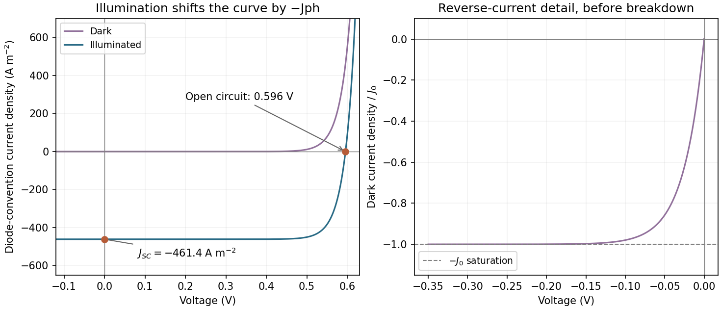

Assume one collected electron per absorbed photon, ideality factor one and . The question does not specify temperature, so the result should also be understood through its temperature-dependent formula. The photocurrent density isAt open circuit the diode current balances that photocurrent:Using gives approximately . These are current densities, so no device area is needed. Incomplete collection would replace by the collected current and reduce this estimate.
Without texturing, more incident photons generally escape by reflection, so the absorbed flux and decrease. Holding and temperature fixed, the voltage falls logarithmically: if absorption is multiplied by and , then . A real texture also changes surface area and recombination, so an unchanged is an assumption rather than a guarantee.
C2 is favoured by kinetic control; C1 is favoured by thermodynamic control. Starting from the central reactant well, the path towards C2 has the smaller activation barrier, so it normally forms faster at low temperature or short reaction time, assuming comparable prefactors. C1 lies lower in energy and is the more stable product on the drawn energy scale.
Raising temperature can make the larger barrier accessible and permit equilibration through reverse reactions. If products interconvert and entropy contributions do not reverse the energy ordering, the equilibrium mixture then favours C1. It would be incorrect to say that high temperature alone guarantees C1: an irreversible reaction may remain kinetically controlled, and the figure does not provide the full temperature-dependent free energies. The useful distinction is rate selection before equilibration versus relative free energy after equilibration.
Remove the gaseous coproduct as it forms, for example by a controlled inert-gas sweep or reduced pressure compatible with the solvent and apparatus. Lowering its partial pressure reduces its chemical potential. For the decomposition equilibrium,so removing G lowers the reaction quotient and drives net conversion towards F until equilibrium is re-established. As D is consumed, reversible conversion from E can replenish it, allowing the coupled network to feed F.
Removing or selectively precipitating F can have a similar effect if feasible. Heating may increase the rate, but its effect on equilibrium requires the reaction enthalpy; a catalyst accelerates equilibration without changing the equilibrium constant. The gas-removal argument works because it changes product activity, not because it changes the identity of the catalyst.
Two neutral carboxylic acids can form a carboxylic acid dimer with two reciprocal O–H···O=C hydrogen bonds. In water, each acid group already makes favourable solvent contacts. Association must displace some of those contacts and loses translational freedom, so the extra stabilization of the dimer may be small. Any ionized carboxylate population also cannot form the same neutral two-donor carboxylic acid dimer.
A nonpolar, weakly hydrogen-bond-accepting solvent such as dry toluene or a compatible hydrocarbon generally favours this dimerization relative to water, provided the acid dissolves. The solvent competes less strongly for the donor and acceptor sites. Dilution still disfavors the dimer because : the dimer fraction depends on concentration even in a favourable solvent. Thus trace dimer in the aqueous sample is not evidence that the acid lacks hydrogen-bonding ability.
Reversible imine formation and disulfide exchange provide two suitable dynamic covalent chemistry reactions.
An aldehyde and a primary amine can reversibly form an imine with loss of water:Multifunctional components can build rings or cages. Acid catalysis, solvent and water activity must permit both formation and hydrolysis or exchange, so that initially incorrect connections can rearrange.
For disulfide exchange, a thiolate attacks a disulfide and substitutes one sulfur-containing fragment:Suitable pH, redox conditions and exchange kinetics let a library of connectivities equilibrate. A template that stabilizes one assembly can shift the library towards it. Reversibility under the actual conditions is essential: calling a covalent reaction “dynamic” does not make a kinetically trapped product mixture equilibrate.
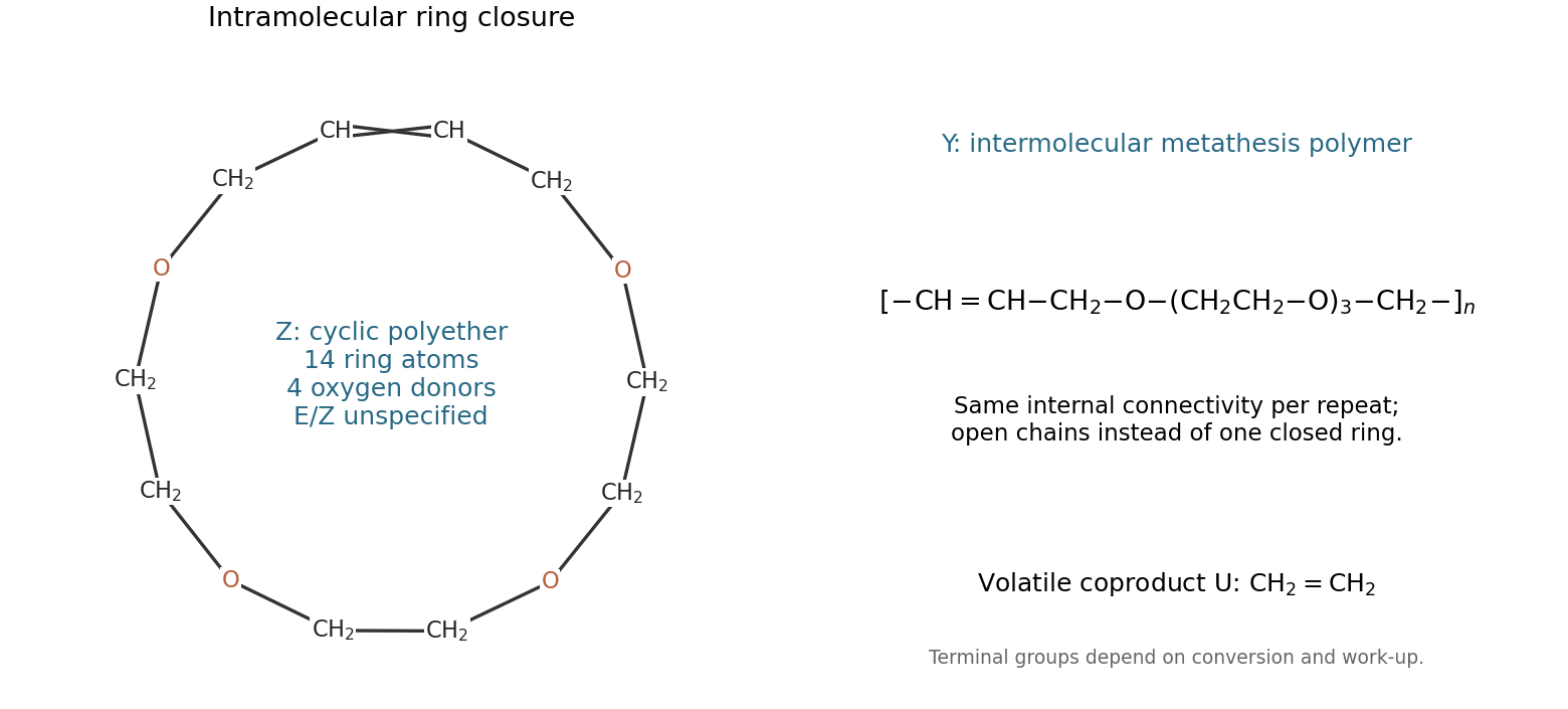
The two terminal alkenes undergo olefin metathesis. Their terminal methylene groups combine to give U = ethene, . Connecting the two internal alkene carbons of the same molecule gives Z, the unsaturated crown ether macrocycle. Following the drawn chain gives four oxygens, six carbons in the three internal ethylene links, two O-adjacent methylenes at the ends and two alkene carbons: a 14-membered ring containing four oxygens.
The ring connectivity is specified completely by the cyclic sequenceThe final methylene reconnects to the first alkene carbon. The examination does not fix alkene stereochemistry, so a single E/Z assignment is not required.
At high concentration, intermolecular encounters compete strongly with ring closure, giving Y, an unsaturated polyether formed by acyclic diene metathesis polymerization. Its repeat connectivity can be writtenFor a finite linear chain, terminal groups depend on conversion and work-up; its internal repeat is the relevant structural answer. Reduced pressure removes ethene and promotes metathesis conversion, while dilution reduces bimolecular chain growth relative to intramolecular closure. These competing routes are documented by the original authors' chemical study.[ref]
Template-Directed Ring-Closing Metathesis by Michael J. Marsella and others. 1997, macrocycle formation and competing unsaturated-polyether formation

The cation acts as a noncovalent template. Coordination to the ether oxygens folds the open chain into conformations with its two alkene ends close together. This increases their effective local concentration and reduces the conformational search needed for ring-closing metathesis. The bound cyclic product is also stabilized relative to unbound alternatives, which can favour it in a reversible reaction network.
A well-matched ion therefore suppresses competing intermolecular connections and increases the isolated or analytical macrocycle yield. It need not become covalently incorporated into Z; it can be removed by changing the binding conditions during work-up. Nor is it necessarily the metathesis catalyst: the ruthenium complex performs bond reorganization, whereas the cation primarily changes preorganization and relative stability. A yield increase alone does not separate a kinetic templating effect from a thermodynamic one, and both can contribute.
The chemically supported assignment isThe four oxygen donors can converge around the small lithium ion to organize the alkene ends efficiently. The larger sodium and potassium ions are less well matched to this particular folded four-oxygen binding environment, with potassium giving the weakest enhancement in the stated comparison. This is a match between donor geometry, solvation and cation size, not a universal rule that lithium templates every crown ether best.
The primary chemical record supports the identity assignment: the inventors' Table 1 reports a strong lithium enhancement for the 14-membered product, with much smaller effects from sodium and potassium. It lists the potassium yield as , whereas this examination gives ; that discrepancy should not be hidden by treating the exam numbers as a verbatim reproduction. The ion assignment follows the structure and the documented templating comparison, rather than the numerical yield alone.[ref]
Template-directed metathesis patent by Robert H. Grubbs and others. US6080826A, Table 1 and discussion of the 14-membered ring: Li, Na and K comparison
An organic liquid electrolyte gives good wetting and relatively high room-temperature ionic conductivity. A dissolved lithium salt supplies mobile ions, while a suitable solvent mixture supports operation beyond the narrow water-stability window. The liquid infiltrates a porous electrode and accommodates modest dimensional changes, helping lower interfacial resistance.
The disadvantages include flammability or combustibility, leakage, solvent volatility and interfacial decomposition outside the stable potential range. A solid electrolyte interphase can passivate the negative electrode, but its formation consumes lithium and electrolyte and its continued growth increases resistance. An electronically insulating separator remains essential. Ionic conductivity alone does not guarantee safety or a large lithium-ion transference number, and low temperature can sharply increase resistance.
A solid polymer electrolyte is flexible, lightweight and potentially easier to make into a thin continuous separator. It can reduce free-liquid leakage and give compliant contact with a rough electrode. Ether-containing polymers, for example, coordinate lithium ions; ionic motion can be coupled to segmental motion of the polymer chains.
Many such polymers have inadequate conductivity at room temperature because crystallinity and restricted chain motion impede ion transport. Heating, adding plasticizer or reducing crystallinity can improve conductivity, but may sacrifice mechanical stiffness or reintroduce liquid-like hazards. Oxidative stability and compatibility with lithium-rich negative electrodes also constrain the usable voltage range. A soft polymer film is not automatically a complete barrier to lithium filament penetration; defects and local current concentration remain important.
A ceramic oxide electrolyte can be nonvolatile, nonflammable and mechanically stiff, with some compositions supporting useful lithium-ion conductivity. A dense, electronically insulating layer can serve as both electrolyte and separator, reducing the amount of flammable liquid.
Its principal difficulties are brittle fracture, processing temperature, grain-boundary resistance and imperfect solid–solid contact. Rigid surfaces do not automatically conform to porous electrodes, and cycling-induced volume changes can create gaps and concentrated current paths. Chemical or electrochemical reactions at either interface may produce a resistive interphase even when the bulk ceramic is stable. Thin dense fabrication, suitable protective interlayers and controlled pressure can help, but add manufacturing complexity and inactive mass. Mechanical stiffness alone does not guarantee immunity to short circuits along pores or grain boundaries.
During discharge, the graphite-based electrode is the anode, where lithium is deintercalated and electrons are released; the cobalt-oxide electrode is the cathode, where lithium and electrons are inserted. Adding the stated half-reactions givesThe supplied potentials are not, strictly, the potentials of those two insertion reactions. Approximating the negative-electrode potential by and using the proton-coupled cobalt reduction as a proxy for the positive electrode gives the intended rough estimateThis is a proxy estimate, not an exact thermodynamic derivation for the specified lithium-ion cell. The graphite insertion chemical potential differs from lithium metal, and lithium insertion into is not the supplied proton-insertion reaction. Actual voltage depends on lithium composition, activities and the nonaqueous electrolyte; the source's aqueous notation does not make a practical graphite–cobalt-oxide cell an aqueous battery. Exact insertion potentials or free energies would be needed for a more rigorous calculation.
One mole of the overall discharge reaction transfers one mole of electrons. Count both active electrode reactants, including the graphite host:Using the preceding constant-voltage approximation,so the ideal active-material specific energy isThis assumes complete one-electron utilization and the proxy throughout discharge. It is not a packaged-cell value or a cathode-only value. A varying equilibrium voltage requires integrating ; using a maximum voltage as a constant average overestimates the delivered energy.
The ideal estimate divides fully utilized electrochemical energy by active reactant mass alone. A real cell also contains electrolyte, separator, binder, conductive additive, current collectors, tabs, casing and safety components. Electrode balancing requires excess capacity on one side, and useful discharge does not generally span complete cobalt-oxide delithiation and a constant . Ohmic, kinetic and concentration losses lower the loaded voltage. These effects can readily bring the cell-level value well below the active-material proxy.
Improvements include higher-capacity host materials, stable higher-average-voltage positive electrodes, thinner inactive layers, lighter current collectors and packaging, and better utilization at practical electrode thickness. Each has a trade-off: very thick coatings impede ionic transport, more energetic electrodes may be less stable, and reducing the negative-electrode safety margin can promote lithium plating. Improving active-material capacity helps only if the added support, electrolyte and safety requirements do not consume the gain.
A lithium–oxygen system can have much greater theoretical active-material specific energy because it avoids the heavy transition-metal host and carbon host of the preceding insertion cell. Oxygen can be taken from the surroundings, but a mass comparison must say whether that oxygen is counted.
The peroxide reaction transfers two electrons per unit. If oxygen is counted, the reactant mass per two electrons iscompared with for two electrons in the idealized lithium-ion reaction. At the same average voltage, the active-material specific energy would therefore be larger by . If only stored lithium is counted, the ideal mass advantage is larger still, but this excludes the oxygen and is not a like-for-like closed-cell mass basis.
The source supplies no lithium-peroxide formation free energy or oxygen-electrode potential, so it does not determine an absolute lithium–oxygen voltage or specific energy. Real devices require an oxygen electrode, gas-management and electrolyte; insulating discharge products, parasitic reactions, charging overpotential and mass transport reduce the practical advantage. The question's reaction is chemical oxygen reduction, not a biological energy pathway.
For one homogeneous thermoelectric material, the dimensional thermoelectric figure of merit isThe dimensionless quantity is . The Seebeck coefficient measures the open-circuit voltage response to a temperature difference and reflects the energy asymmetry of charge-carrier transport. The electrical conductivity depends on carrier density and mobility and sets electrical loss; . The thermal conductivity is , with contributions from carriers and phonons, and represents unwanted heat leakage.
Increasing carrier concentration usually raises while reducing once transport becomes strongly degenerate. The electronic part of also tends to rise, approximately through the Wiedemann-Franz law where applicable. This competition produces an intermediate optimum, commonly in heavily doped semiconductors, rather than in a very resistive insulator or an ordinary high-carrier-density metal. The optimum depends on band structure and scattering; the schematic is not a universal measured concentration curve.
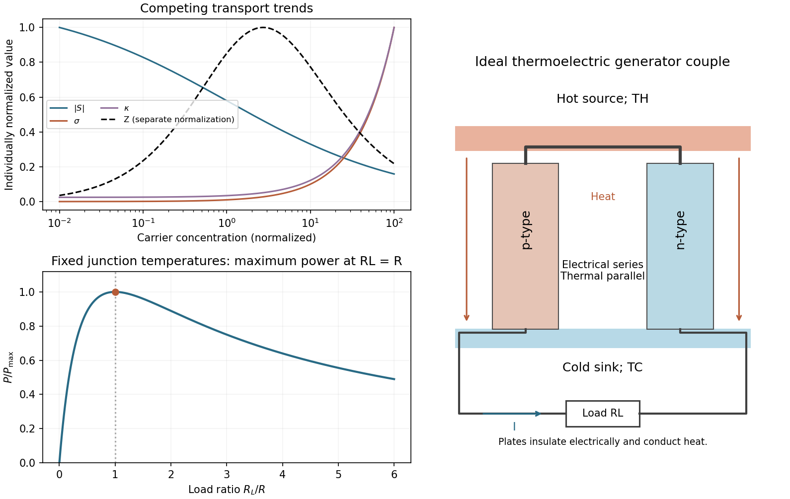
Thermoelectric carrier trade-offs, a generator couple and load matching
. Original normalized carrier-property curves, a circuit schematic and the calculated dimensionless load-power curve. The carrier curves illustrate competing trends and do not assert material-specific measurements. Details.
A generator couple has a p-type and an n-type thermoelement joined electrically at the hot face, with their other ends connected through a load at the cold face. The legs are electrically in series and thermally in parallel. Electrically insulating, thermally conducting plates couple them to the hot source and cold sink; metal interconnects carry current. The Seebeck effect provides an open-circuit electromotive force , where the magnitude of is the difference between the two leg Seebeck coefficients.
For fixed junction temperatures, constant properties and internal resistance ,Differentiate with respect to load resistance:The derivative changes from positive to negative at , soThe load voltage is then half the open-circuit voltage. The heat source and sink must sustain the temperature difference; an isolated hot object cools as energy is extracted. Maximum power and maximum conversion efficiency are different operating points: the efficiency-optimal load is generally larger than .
For the thermoelectric couple figure of merit, the coefficient denotes a pair difference, whereas the table gives one value each for resistivity and thermal conductivity without saying whether they are per-leg or effective pair values. To keep the factors consistent, first take both legs to have the listed and , and equal as stated. ThenThis is identical to treating each symmetric leg as having Seebeck-coefficient magnitude . The mean temperature is , giving .
If the examination instead intends its and as already combined effective pair coefficients in and , the alternative convention gives , with . That convention must be declared; using the full pair Seebeck difference with individual-leg while omitting both factors of two would overestimate the device figure of merit by four.
Use absolute temperatures , and . With the explicit identical-per-leg interpretation from the preceding part,and the stated ideal efficiency expression givesWith the alternative already-combined pair convention, instead gives . Both lie below the Carnot efficiency . These are constant-property ideal conversion efficiencies, neglecting contact resistance, parasitic heat paths and temperature dependence. They are not the efficiency specifically at the maximum-power load.
The temperature difference is , so the pair open-circuit voltage isFor two identical legs with the stated per-leg geometry,At matched load ,The load voltage is , and multiplying it by the current reproduces the power. If instead denotes an already combined pair resistivity, , giving and . These alternatives follow the same convention distinction as the figure-of-merit calculation; they should not be mixed.
For identical couples connected electrically in series, the open-circuit voltage is and the internal resistance is . At the module's matched load ,Maintaining the stated temperature difference across every couple therefore requiresunder the identical-per-leg interpretation. Sixty-four ideal couples supply about ; sixty-three supply about . The alternative already-combined pair-resistance convention gives 32 couples, each producing approximately .
The module is thermally parallel: adding couples increases the heat flow that must be supplied and rejected. The count assumes that source and sink keep the actual leg junctions at the stated temperatures and that interconnect losses are negligible. Connecting the couples does not multiply the maintained temperature difference.
Nanowires can increase by reducing lattice heat conduction more strongly than they degrade useful electronic transport. A wire diameter comparable to important phonon mean free paths introduces boundary scattering and reduces the lattice part of thermal conductivity. Interfaces, surface roughness and suitable nanostructure can suppress long-mean-free-path phonons while preserving shorter-mean-free-path carrier transport.
Electronic confinement or energy-dependent scattering can also change the Seebeck coefficient and thermoelectric power factor, but neither improvement is automatic. Surface depletion, disorder and contact resistance may instead reduce electrical conductivity; a smaller wire is not necessarily better. The necessary comparison is the complete ratio over the operating temperature range. The experimentally established benefit of nanostructuring is especially clear when it suppresses phonon heat conduction while retaining a useful power factor.[ref]
High-Thermoelectric Performance of Nanostructured Bismuth Antimony Telluride Bulk Alloys by Bed Poudel and others. 2008, nanostructured-alloy thermal-conductivity and figure-of-merit measurements
Articles by others on the same topic
There are currently no matching articles.