At an air–glass interface, resolve the incident unpolarized light into components perpendicular () and parallel () to the plane of incidence. The Fresnel equations give the parallel reflection coefficientAt Brewster's angle, . Together with Snell's law, this gives and . Thus, taking the incident medium to be air,The remaining reflected component has linear polarization perpendicular to the plane of incidence. This assumes a transparent, nonmagnetic glass with negligible absorption.
Let be the intensity from either fibre alone at the observation point, assuming equal output intensities, matching polarizations and negligible drift. The screen samples the relative phase between the two outputs. For an ideal monochromatic laser, first-order optical coherence is complete andThe interference fringes are approximately equally spaced in the small-angle far field, with a slowly varying diffraction envelope. If the output separation is and the screen distance is , the interference fringe spacing is approximately . Equal phases at the two input ends do not ensure a central bright fringe: the extra fibre contributes carrier phase in addition to the free-space optical path difference.
For a finite linewidth, the time-averaged interference signal becomesHere may be defined for the slowly varying field envelope, with the carrier phase already included in . A realistic laser therefore gives reduced interferometric visibility; for , its extrema are and .
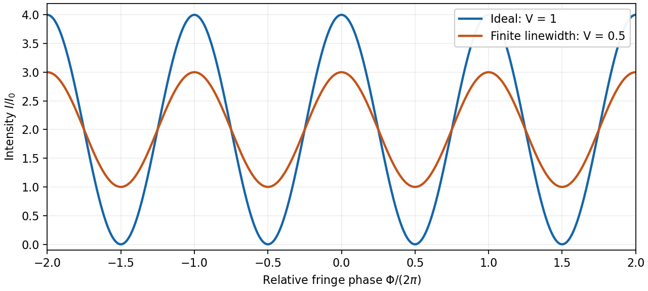
Ideal and finite-linewidth interference for equal output intensities
. Details. For a Lorentzian line shape of frequency full width at half maximum , temporal optical coherence givesThe relevant index is the group index. Using the intended nondispersive approximation ,This delayed-fibre linewidth measurement assumes the loss of contrast comes from linewidth. Unequal output intensities, polarization mismatch or mechanical phase fluctuations also lower interferometric visibility. If dispersion matters, the stated phase index alone does not specify the necessary group index.
Use axes adapted to the two orthogonal rotations in the diagram:For a linearly oscillating Hertzian dipole with real unit axis and total time-averaged radiated power , the angular distribution of electric dipole radiation isThe normalization follows from . Equal readings therefore implyHere , since otherwise all components would vanish. Reversing the axis is immaterial, so choose . The complete family isDefine , , and . Then , and the absolute intensity fixesFor the measured distance and intensity, the allowed axes and powers are:
- : , .
- or : , for either axis.
- : , .
The intensity data do not select a unique orientation or total power. This is the dipole-axis ambiguity from three intensity measurements: the readings constrain squared projections and lose their signs. For example, the first branch makes an angle with , but the other branches are equally consistent with the three measurements. A further suitable observation direction or polarization measurement is needed to remove the ambiguity. The calculation uses radiation-zone intensities, as appropriate to the Hertzian dipole model.
Molecules in clean air are much smaller than visible wavelengths. Their induced electric dipole moments undergo Rayleigh scattering. Away from molecular resonances, the induced dipole amplitude is approximately , with only weak wavelength variation in the polarizability . The radiation-zone electric field is proportional to , so the scattered intensity satisfiesThis is the Rayleigh scattering wavelength dependence. For equal incident intensities, light scatters about times as strongly as light. Thus light scattered out of the direct solar beam and into our line of sight is enriched in blue wavelengths.
The dipole mechanism also determines the Rayleigh scattering angular pattern. For unpolarized light, its angular factor is ; near scattering, the scattered light has strong linear polarization. The sky's perceived colour depends additionally on the solar spectrum, atmospheric transmission and the eye's spectral response, so the law alone does not predict a violet sky. Over a long near-horizontal path the direct beam loses more short-wavelength light, explaining red sunsets. Large aerosol particles instead produce Mie scattering, which is less strongly wavelength-selective and can make haze look whitish.
A phased array uses fixed antennas driven coherently, with adjustable electronic delays or phases. Changing those relative phases changes the direction of constructive interference.
For identical elements at , take time dependence and feed phase . In a far-field direction at angle from the array normal, the array factor isMultiply by the single-element antenna beam pattern to obtain the total angular intensity. All elements add in phase in the selected direction ifThus electronic control of steers the beam to without moving an element. Reciprocity gives the corresponding directionality in reception.
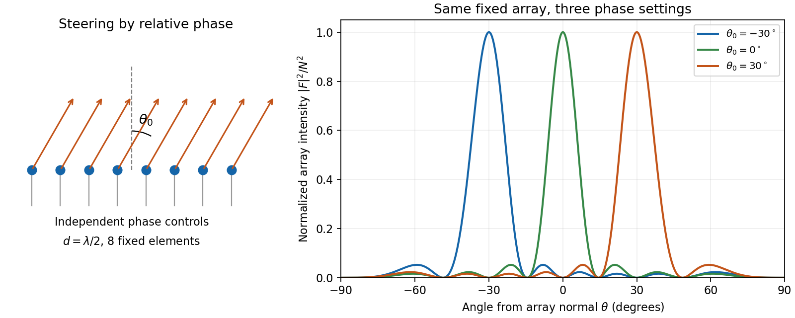
An electronically steered linear array and its normalized array factors
. Details. The aperture controls angular resolution: the nearest nulls obey , giving a main-beam width of order away from endfire. Additional equally strong maxima can occur when ; these are grating lobes. Choosing avoids them for all steering directions, with the usual limiting spacing. Amplitude tapering reduces side lobes at the cost of a wider main beam. For a broad frequency band, true time delays preserve steering more accurately than frequency-independent phase shifts.
A charge moving uniformly through a transparent dielectric can emit Cherenkov radiation if its speed exceeds the phase velocity of light in that medium:It need not exceed the vacuum speed . The passing charge polarizes the medium; the induced response produces radiation that adds coherently along selected directions. Equivalently, phase matching along the trajectory requires . Since ,Here is the angle of the emitted light rays to the forward particle velocity: the rays form a cone around the track. With dispersion, both the threshold and cone angle depend on frequency; only transparent frequency bands satisfying the threshold contribute escaping radiation.
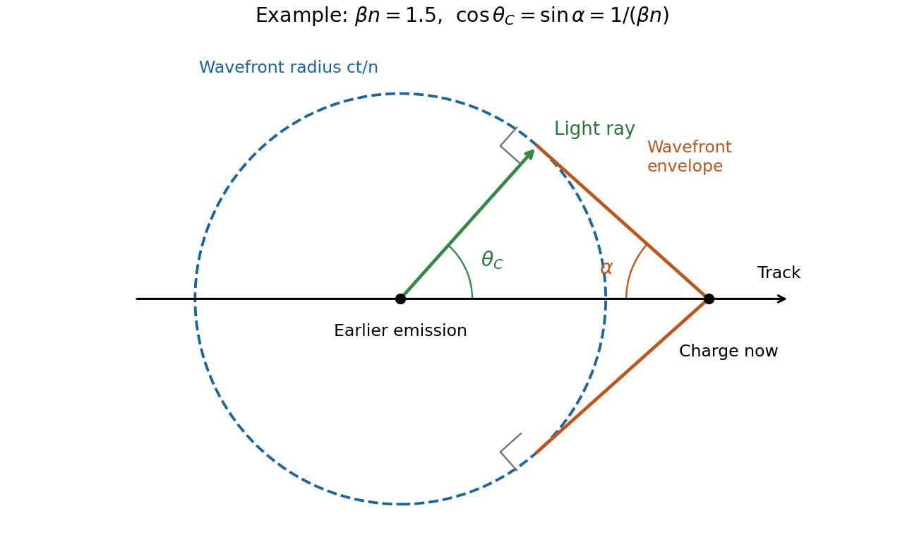
In the wavefront construction, a disturbance emitted a time earlier has radius , while the particle has moved . Tangents from the present particle position to these wavefronts make a backward-opening wavefront cone of half-angle , where . The light rays are normal to this cone. Consequently : the Cherenkov photon-cone and wavefront-cone angles are complementary, rather than identical.
General pure state. Use time dependence . The most general nonzero Jones vector can be writtenThere are four real parameters in the full complex field. Removing overall intensity and the unobservable common phase leaves two real degrees of freedom for pure polarization, and . Their endpoint degeneracies simply reflect the fact that the phase of a vanishing component is irrelevant. A single Jones vector cannot represent partially polarized light.
Three linear polarizers. Define the transmission axis . An ideal linear polarizer has Jones matrix . For definiteness label as right-circular in the chosen convention; reversing the handedness convention changes no intensity below. The first polarizer produces . The intermediate polarizer and final analyzer then giveso Malus's law givesThe maximum is at , and the transmission vanishes at . The first polarizer accounts for an initial factor ; retaining that factor is essential when quoting transmission relative to the incident circularly polarized beam.
Waveplate and quarter-wave matrix. A lossless waveplate has linear birefringence: its orthogonal fast and slow axes have indices . A thickness produces slow-minus-fast phase retardationResolving the incident Jones vector into the plate axes, advancing the two phases and transforming back gives, up to a common phase,A quarter-wave plate has modulo . With and , its Jones matrix is thereforeIn particular . Equal incident components along the two axes acquire a relative quarter-cycle phase, converting linear polarization to circular polarization; an incident component along either principal axis stays linearly polarized.
Half-wave replacement. A half-wave plate has and henceIt converts the -polarized output of the first polarizer to a linear state at angle . The final analyzer givesThe maximum is , because the ideal half-wave plate loses no light after the first polarizer.
Quarter-wave replacement. The transmitted amplitude is , givingMore generally, the retarder gives . All three requested curves have the same zeros and angular period, but different heights:
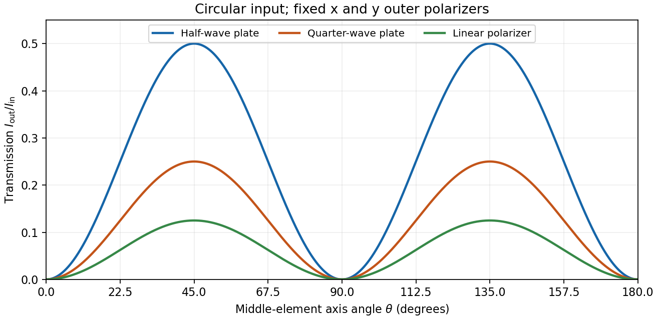
Transmission through crossed outer polarizers with three different middle elements
. Details. Preparing an arbitrary ellipse. Yes: two rotatable quarter-wave plates already suffice. Let the input left-circular state be . Up to an overall phase, any target pure polarization can be parameterized by its polarization ellipse:Here is the major-axis orientation, and sets the signed minor-to-major semiaxis ratio . First note directly from thatChoose the two fast-axis angles asThe first quarter-wave plate produces linear light at . In the axes of the second, its components are ; the second gives precisely . This proves pure-polarization preparation with two quarter-wave plates, including the linear and circular limiting cases. A half-wave plate can also rotate the axes, but is not required. The phrase about left-handed input is understood as left-circular light in this construction; the explicit vector fixes the convention.
Switchable retardation. The electro-optic Kerr effect induces linear birefringence quadratic in a static transverse electric field. Defining the coefficient by , its phase retardation isThe two eigenpolarizations are linear, parallel and perpendicular to the applied field. Thus an appropriate field produces a switchable quarter-wave plate:The sign of determines which axis is fast. Switching the field off removes the induced retardation, assuming no residual birefringence.
The Faraday effect instead gives circular birefringence for a longitudinal magnetic field. The two circular eigenmodes acquire different phases, rotating a linear polarization throughwith sign set by the handedness convention and the Verdet constant . Its Jones matrix in the linear basis is a real rotation, up to a common phase. It preserves the ellipticity of a pure state, so a linear input remains linear. A phase difference between circular eigenmodes rotates a linear state by ; it does not make it circular. The Kerr device supplies the switchable quarter-wave plate; a Faraday rotator alone does not.
Gauge freedom. The magnetic vector potential satisfies . The transformationleaves unchanged because the curl of a gradient is zero. For time-dependent fields, transform the electric scalar potential as as well, so that is unchanged. The scalar must have the regularity and single-valuedness appropriate to the physical region and its boundary conditions. Local values of therefore depend on the gauge transformation.
Gauge and nonzero component. In the standard axisymmetric Coulomb gauge representative for the long-solenoid approximation,The divergence vanishes since is independent of the azimuth. Inside, this agrees with the usual symmetric gauge representative . The Coulomb gauge condition alone does not force the other two components to vanish; the symmetry, regularity and customary boundary choice select this representative from the remaining gauge freedom.
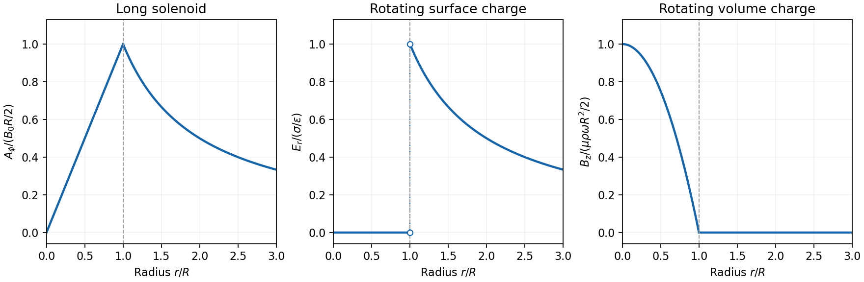
Radial dependence. Write the interior magnetic field as , where for a vacuum solenoid of solenoid turn density . Its exterior magnetic field vanishes in the infinitely long idealization. Applying Stokes theorem to a coaxial circle gives . Therefore the Coulomb-gauge vector potential of a long solenoid isIt grows linearly inside, is continuous at , and decays as outside. Although its exterior curl is zero, its circulation is the enclosed magnetic flux . No regular single-valued gauge function removes it throughout the exterior while preserving this circulation.
Electric field of the rotating charged surface. For clarity retain absolute permittivity and permeability in the cylinder formulae; setting them to unity gives the rationalized-unit convention in the question. If the stated unity means relative material constants in SI, use instead. Assume prescribed charge densities in the laboratory frame and the nonrelativistic, steady-rotation model.
The axisymmetric surface charge is stationary as a distribution even while the material rotates. A Gaussian cylinder of length has enclosed charge zero for and for . Gauss's law therefore givesThe radial electric field jumps from zero to at the surface and then decays as . Its direction reverses for negative . The angular velocity does not enter this electric-field result for a specified surface charge.
Magnetic field of the volume-charged cylinder. A shell of radius and thickness has surface charge , azimuthal surface current , and the field of an infinite solenoid: inside that shell and zero outside it. At radius , only shells with contribute. Thus the magnetic field of a rotating charged solid cylinder isWith no applied background magnetic field, outside. The profile is parabolic, largest on the axis and zero at the boundary. The sign follows . As a check, the current density is , and Ampère's circuital law gives , as required.


Electron impulse when the current is switched off. Choose positive so the initial magnetic flux is along . Faraday's law of induction gives, outside the solenoid,For an Electron of electric charge , treat its position as fixed while the short pulse acts. The inductive impulse outside a switched solenoid isConsequently the nonrelativistic final velocity isThe induced electric field circulates in the positive azimuthal direction while a positive flux decreases, so the Electron accelerates in the negative direction. Once the pulse has passed, there is no exterior field and it travels along the tangent at the impulse point, rather than continuing in a circular orbit. If the resulting momentum is relativistic, use instead. The sudden-switch result assumes negligible displacement during the pulse and the usual quasistatic electromagnetic induction approximation; “instantaneous” switching does not mean instantaneous propagation of fields to arbitrary distance.
One can check the sign using conserved canonical angular momentum: axial symmetry conserves . Initially , and finally , so .
Interferometric measurement at constant current. Use a coherent Electron beam split into two paths passing on opposite sides of a shielded long solenoid, then recombine them to form interference fringes. Keep the current constant during the passage and suppress leakage fields on the paths. In the Aharonov-Bohm effect, the phase difference due to the magnetic vector potential is the closed-loop integralThe overall sign reverses if the path orientation is reversed. The displacement in fringe periods is , so the measured fringe shift is linear in and repeats whenA gauge transformation adds a gradient whose closed-loop integral vanishes for a single-valued . Endpoint changes in Electron wavefunction phase cancel in the interference measurement. The measured Aharonov-Bohm phase is therefore gauge invariant: it determines the flux, or equivalently the circulation of . In the chosen Coulomb gauge this implies , but the experiment does not select or measure a unique local vector potential independently of gauge.
Far field of the rotating sphere. Interpret uniform charge as uniform volume charge of total , and take . The magnetic dipole moment of a rigidly rotating charge distribution isIts axial component is . For a solid sphere, and , soThe magnetic field of a rotating charged spherical body is a static magnetic dipole field at large distances:In particular, . Both the angular mean of the magnitude and its root mean square therefore scale as ; the latter is . The angular average of the vector is zero, which is different from average strength. Steady rotation leaves the charge and current distributions stationary, so this is magnetostatics, not a radiative field. If uniform charge instead means a thin spherical surface, replace the dipole moment by ; the angular pattern and scaling are unchanged.
Articles by others on the same topic
There are currently no matching articles.