Topics (384k) Articles (398k) Users (410) Discussions (242) Comments (383) Files (13k) New article

Zea is a taxonomic genus of grasses that includes maize and its wild relatives, commonly called teosinte. Its native distribution is in Mexico and Central America; widespread cultivated and introduced populations should be distinguished from that native range.[ref]
https://powo.science.kew.org/taxon/urn%3Alsid%3Aipni.org%3Anames%3A19280-1. Kew taxonomic record, accepted genus and native range
The plants exhibit monoecy: male and female flowers occur on the same plant, in separate inflorescences. The male inflorescence is terminal, while the female inflorescences are borne in leaf axils. In maize, the conspicuous male structure is the tassel, and the female structure develops into the ear. Thus an ear and a tassel are different reproductive structures of one plant.[ref]
Comparing maize with teosinte makes Zea a powerful system for studying domestication. Differences in branching can arise through changes in gene regulation: work on the teosinte branched1 gene connects the compact architecture of cultivated maize with altered control of shoot development.[ref]
The evolution of apical dominance in maize by John Doebley and others. Abstract, branching phenotype and tb1 expression
Triticum is the taxonomic genus containing wheat, within the grass family Poaceae. A taxonomic genus groups related species; it is consequently broader than Triticum aestivum, the species used as common bread wheat. Keeping these ranks separate prevents a result measured in one cultivated species from automatically becoming a statement about every Triticum.[ref]
Triticum in the Integrated Taxonomic Information System. TSN42236, rank, family and direct children
The genus is especially useful for studying polyploidy. In bread wheat, three related ancestral genomes are represented twice, conventionally written AABBDD. Seven chromosomes per ancestral set give chromosomes. The letters label related inherited sets; they do not mean that there are only three chromosomes.[ref]
Dual effect of the wheat Ph1 locus on chromosome synapsis and crossover by Azahara C. Martín and others. Introduction, hexaploid wheat genome constitution
During meiosis, a chromosome must distinguish its homologous chromosome from similar chromosomes belonging to the other ancestral sets. Comparing chromosome pairing in ordinary wheat with pairing after alteration of the Ph1 locus tests how this distinction is controlled. Thus Triticum connects crop classification with the cell-level problem of distributing multiple related genomes reliably between generations.[ref]
Dual effect of the wheat Ph1 locus on chromosome synapsis and crossover by Azahara C. Martín and others. Results, comparison of synapsis and crossovers with and without Ph1
Zero-offset drift of an integrated flow measurement is a false accumulated volume caused by an additive error in the measured volumetric flow rate. If , thenA constant bias gives error ; a linearly changing bias gives . A small flow offset can therefore produce a conspicuous trend after integration.
For a constructed offset 0.004 L/s, the error after 60 s is 0.24 L. If the true flow alternates symmetrically between forward and reverse directions, its net integral can be zero while that false trend remains. The drift is an error in the integrated signal, not evidence that the apparatus necessarily accumulated that amount of gas.
A pneumotachograph signal chain can be modeled as . An error in the estimated zero becomes an additive flow error, while an error in changes the scale. The manufacturer's primary manual treats no-flow zeroing and known-volume calibration separately, explicitly connecting zero-flow error with steady integrated-volume drift.[ref]
Front-end Signal Conditioners Owner’s Guide. Printed pp. 151–153, Calibrating the Flow Head and Reducing Drift
A bidirectional bench example separates those effects. Let the inferred integral be , where is a gain factor. Equal-time strokes transporting true volumes and givesoWith L, s, L and L, the inferred gain is 1 and the offset is 0.025 L/s. This is a constructed linear calibration model, not a measured specification of a particular instrument.
Instrumental drift, gain error, leakage and a real net flow can create different records. Subtracting an arbitrary fitted trend may hide genuine accumulation as well as measurement bias. A physical no-flow reference and a known displaced volume test the relevant assumptions more directly than forcing every integrated trace to return to its initial value.
Spectral-contrast conditioning in nail optics describes how measurement errors are amplified when thickness or tissue parameters are recovered from spectral differences. A model can be identifiable in exact arithmetic while its parameter estimates are too sensitive to small signal or calibration errors to be useful.
For the original simplified plate model with known coefficients and wavelength-independent effective reflectance , thickness isLet each log signal have standard uncertainty and their correlation be . The first-order thickness uncertainty isThe covariance term belongs to the uncertainty calculation; treating every spectral error as independent can be misleading.[ref]
With stipulated and independent errors, coefficient differences and give thickness uncertainties about 0.0141 and 0.141 mm, respectively. A tenfold loss of spectral contrast produces tenfold error amplification. At the larger contrast and correlation 0.9, the modeled uncertainty is approximately 0.00447 mm. These are local model calculations, not validated precision claims for nail measurements.
Coefficient calibration also matters. If signal-ratio error and error are independent,Collecting more signal averages does not eliminate the second term when the same uncertain calibration is reused.
Offset sensitivity of log-ratio nail models distinguishes error types. A common multiplicative factor cancels from ; a common additive offset generally does not cancel from . Background light or unseparated fluorescence can therefore bias an otherwise precise ratio. The primary nail-transmission experiment explicitly included a fluorescence correction.[ref]
A random planar map is a planar map sampled from a specified probability distribution. A common finite model chooses uniformly among rooted maps with edges, where a root is a distinguished oriented edge. Sampling maps means sampling embeddings as well as abstract graphs; distinct cyclic arrangements of edges can describe different maps.[ref]
Random Planar Geometry by Jason Miller (2020). opening sections, rooted maps and finite random-map models
For a connected map on the sphere, the Euler formula for a connected planar graph gives . Thus conditioning on fixes but permits random numbers of vertices and faces. One may instead restrict every face to degree three or four, giving random triangulations or quadrangulations. These are different probability models and need not yield the same finite-size statistics. Distances in large random maps motivate probabilistic models of random geometry.
A reference-point transformation of a pitching moment coefficient changes the location about which the aerodynamic torque is reported while leaving the physical loads unchanged. The pitching moment coefficient therefore requires a reference point as well as a sign, axis and normalization.
Let point from the old reference to the new reference , with force and moment vectors expressed in common axes. The wrench translation law isIt follows immediately by replacing each old force arm with before summing their cross products. The primary Drake spatial-force documentation gives the same old-to-new offset convention and unchanged force component.[ref]
SpatialForce class in Drake documentation. ShiftInPlace, single-force overload; offset convention and torque update
For a planar example, choose positive aft, positive upward and the right-handed pitch axis so positive moment is nose-up. Write and . Dividing the pitch component by givesHere is dynamic pressure, the reference area and the reference chord. The equation assumes those normalizations remain the same.
In a constructed case, , and an aft shift at the same height give . Adding an upward shift with changes it to 0.064. The aerodynamic loading has not changed between these reports.
A chordwise zero-moment point, when , satisfiesThis is a center of pressure construction, not the definition of an aerodynamic center. If the normal force vanishes while the moment does not, no finite chordwise shift removes that moment. NASA distinguishes the force-plus-moment representation from placing a resultant at the center of pressure.[ref]
Center of Pressure by NASA Glenn Research Center. Aerodynamic Force section
Replacing by a lift coefficient additionally requires transforming between chord-normal and freestream-normal axes; changing a reference point alone performs no such rotation.A laboratory micropipette is a pipette for transferring small measured quantities of liquid, commonly expressed in microlitres. In piston-operated models, the displacement mechanism matters. An air-displacement pipette leaves an air cushion between piston and sample, whereas a positive-displacement pipette places the piston directly against the liquid.[ref]
Weighing a delivered sample provides a concrete check. In a simplified calculation that neglects air buoyancy and evaporation, liquid volume follows from mass and density :For an assumed , a delivered mass of corresponds to . Relative to a nominal setting, the deviation is . These are illustrative values, not calibration data.
A repeated series can distinguish a displaced mean from wide scatter: measurement accuracy and standard deviation describe different aspects of performance. Actual gravimetric checks account for temperature-dependent water density, air buoyancy and evaporation losses. The manufacturer's method uses a conversion factor and an evaporation correction, showing why a displayed volume alone does not establish the quantity delivered.[ref]
Gilson Guide to Pipetting. pp. 46–49, systematic/random error, gravimetric conversion and repeated weighings
The pinning lifetime is the interval during which a pinned memory object must retain its address for all consumers entitled to use a non-relocatable pointer into it. The interval must cover actual memory access, rather than merely the act of handing out the address. Microsoft's
fixed statement guarantees address stability during its body and restricts its declared pointer to that statement; a pointer retained for later work needs a guarantee covering that later work too.[ref]Fixed statement in the C reference by Microsoft. Opening definition and array-element/object-field lifetime guarantees
For an original timing example, suppose a pin starts at0ms, an external operation receives the address at0.5ms, its submission function returns at1ms, and its final memory access finishes at5ms. Releasing the pin at the function's return leaves4ms of possible access after address stability has ended. Releasing it only after completion at5ms can cover the whole access interval. These times describe an illustrative protocol, not a timing claim about a particular runtime or device.
If the pin is active on , every access time must satisfy . With several users, the release point must follow the last access by all of them. A count of outstanding operations can enforce this rule: after two operations start, one completion changes the count from2 to1 and does not permit release; the last completion changes1 to0. Asynchronous pin release therefore depends on a completion guarantee. Requesting that unfinished work stop does not by itself demonstrate that its final access has ended.
The pinning lifetime and data synchronization solve different problems. Stable addresses do not prevent two users from changing the same bytes concurrently; a mutex or another synchronization mechanism may still be needed. Nor should a pin be held indefinitely just because longer protection seems convenient: pinning can obstruct memory compaction, as the pinned memory object layout example shows. The useful interval is long enough for the access contract and ends when that contract permits release.
For conservative photon transport at constant speed , suppose successive scattering directions are independent and isotropically distributed, and free-path lengths follow an exponential distribution of mean . In three spatial dimensions, the resulting long-time diffusion coefficient isHere is the scattering mean free path. These assumptions describe homogeneous, memoryless interactions without absorption.
The velocity autocorrelation function gives a direct derivation. An initially isotropic ensemble has zero mean velocity. During a lag , the probability of no scattering is . No scattering preserves the direction; one or more independent isotropic scattering events give zero expected directional correlation. ConsequentlyThe three-dimensional Green-Kubo formula for diffusion now yieldsThe factor converts the dot-product correlation into one Cartesian component under isotropy.
The same correlation gives the full mean squared displacement:At short times this is ; at long times its leading term is . The model therefore connects direct flights to the diffusive many-scattering limit.
The free-path distribution matters. A fixed-step isotropic random flight with every length equal to has mean-square displacement after steps and elapsed time , giving . Replacing exponential flights by fixed-length flights thus changes the coefficient by a factor of two. For anisotropic scattering, directional persistence instead leads to a transport mean free path; strong absorption and boundaries require additional modeling.
A diffuse photon time-of-flight experiment measures the distribution of delays experienced by light traversing a scattering sample. A short-pulse source illuminates the sample; a reference timing signal starts the clock, and a fast photodetector records returning or transmitted photons. Time-correlated single-photon counting accumulates their delays over repeated pulses into a histogram.[ref]
A useful laboratory comparison keeps the source-detector geometry fixed while changing sample thickness or scattering strength. The apparatus needs a defined optical path, a sample holder and the same detection/timing chain for a reference instrument response function. Longer, repeatedly scattered paths broaden the arrival distribution; absorption changes which paths survive to be detected.
Let denote the sample's optical impulse response in the chosen geometry and the normalized instrument response function. A simple model for the expected count-rate trace iswhere denotes convolution, sets the signal scale and represents background counts. Fitting a transport model after including separates sample broadening from instrumental timing spread. A model for an infinite medium cannot simply be substituted for a finite slab's boundary-dependent detector response.
M. S. Patterson, Britton Chance and B. C. Wilson developed analytic slab responses and compared them with preliminary measurements and Monte Carlo simulations in 1989.[ref]
Time resolved reflectance and transmittance for the non-invasive measurement of tissue optical properties by M. S. Patterson and others. Abstract: picosecond pulses, homogeneous-slab model and comparisons
The shape of the delay distribution provides information beyond total transmitted intensity.The counting electronics also matter: if only the first arrival in each pulse period is recorded, multiple arrivals bias the sample toward earlier times. This photon pile-up must be represented or suppressed by the acquisition conditions, rather than mistaken for faster propagation.[ref]
Time-Correlated Single Photon Counting (TCSPC) by PicoQuant. How Does TCSPC Work?: first-photon pile-up and reconstruction of the delay histogram
Pulse energy measurement with a photodiode estimates incident laser pulse energy from collected signal electric charge. At fixed wavelength, suppose a photodiode has constant calibrated spectral responsivity in amperes per watt and remains in its linear operating range. If is the incident radiant flux, the signal photocurrent is . Integrating over the complete response givesThe units agree because amperes per watt equal coulombs per joule. Spectral responsivity must apply at the measurement wavelength; a broadband pulse requires accounting for its spectrum.
In an original example, let and let the baseline-corrected collected charge be . Then . An ideal charge amplifier with feedback capacitance would produce an output change of magnitude . The amplifier's polarity depends on its circuit convention.
A practical apparatus needs a calibrated detector, a charge-sensitive readout and a measurement window containing the full response. Detector baseline subtraction removes the estimated background, including dark current. A residual constant current of1microampere integrated over10microseconds contributes10picocoulombs; with the example responsivity this is a25picojoule energy error. Extending the window can capture a missing signal tail but also accumulate more background error.
Photodiode saturation invalidates the assumed constant response. Robert E. Vest and collaborators measured pulsed silicon-detector behavior and reported dependencies on applied reverse bias and illuminated area.[ref]
Measuring Pulse Energy With Solid-State Photodiodes by Robert E. Vest and others. Abstract, nonlinear pulsed response and bias/area dependence
A low average optical power therefore does not by itself establish linear response to individual pulses.Rodney W. Leonhardt's calibration report describes a complementary reference method: a slow thermal standard measures accumulated energy, while pulse count and a calibrated beam splitter ratio determine average energy in the test beam.[ref]
Calibration Service for Low-level Pulsed-Laser Radiometers at 1.06 µm: Pulse Energy and Peak Power by Rodney W. Leonhardt. §4, printed pp9–10
This connects a fast photodiode readout to an energy reference without requiring the thermal standard to resolve every pulse.Collected charge measures energy under the stated assumptions; it does not alone determine peak power. A flat30nanojoule pulse lasting100nanoseconds has power0.30watts, whereas a flat pulse of the same energy lasting1microsecond has power0.030watts. Those stipulated rectangular profiles illustrate why pulse shape and pulse duration are additional information.
Photodiode saturation is a departure from the intended proportional response of a photodiode as incident radiation becomes too large for the detector's operating conditions. The simple relation , or its pulse-integrated counterpart , then fails with a constant spectral responsivity . The observed readout can also be limited by amplifier clipping or other circuit effects, so a flattened trace alone does not locate the nonlinearity inside the diode.
Robert E. Vest and collaborators characterized silicon-photodiode response under pulsed illumination, reporting dependence on reverse bias and illuminated area. Their study extends pulse-length characterization and compares a pulsed-radiation calibration with continuous-wave conditions at a synchrotron.[ref]
Measuring Pulse Energy With Solid-State Photodiodes by Robert E. Vest and others. Abstract, nonlinear response, bias/area dependence and calibration comparison
Low average optical power does not by itself ensure that an individual pulse remains within the detector's proportional-response range.An original toy response makes the energy bias explicit. Suppose the collected pulse charge isThis chosen compression law is not Vest's detector model. At low pulse energy it approaches ; at high energy it approaches . With , and true , it gives . Blindly applying the low-level calibration would infer50nanojoules, only half the stipulated energy.
A detector linearity test varies incident energy while holding wavelength, illumination geometry, bias and readout settings fixed. In the toy law, halving the true energy from100to50nanojoules changes charge from20toabout13.3nanocoulombs, rather than to10nanocoulombs. Comparing these ratios with known optical changes can expose compression. Actual attenuation and reference measurements require their own measurement calibration.
The appropriate limit depends on pulse shape, area, bias and readout, not on one universal optical-power number. Detector baseline subtraction can correct an additive offset but cannot reconstruct charge lost through an unknown nonlinear response. Establishing linear operation or characterizing that response is therefore a prerequisite for trustworthy pulse energy measurement with a photodiode.
A photoresistor, also called a light-dependent resistor or LDR, is a two-terminal component whose resistance changes with incident light. A common photoconductive implementation uses an illuminated semiconductor between contacts; an external circuit converts its resistance change into a voltage or current signal. A manufacturer’s CdS datasheet explicitly identifies these names and describes resistance decreasing with visible illumination.[ref]
NSL-5162 CdS photoresistor datasheet by Advanced Photonix. page 1, component description and Light Dependent Resistor designation
The photoconductor mechanism is a change in conductivity through generated mobile carriers. A photoresistor’s resistance is consequently not a calibrated unit of optical power by itself. Material, wavelength distribution, temperature, illumination history and the measuring circuit help determine the observed response.
For an original illustrative model over a limited range, let with , fixed spectrum and geometry. Choose and . Four times the reference optical input gives , rather than one quarter of the original resistance. This stipulated power law illustrates a nonlinear response, not a fitted specification for the cited part.
In a divider with supply and fixed resistor , measuring across givesAt and , the model output rises from at to about at . The logarithmic sensitivity is greatest when , where it is . Choosing a resistor therefore selects an operating region; it does not remove the material’s response law.
The electrical input must also be characterized. The divider seen at its output has Thevenin resistance . A finite-input-resistance voltmeter or an analog-to-digital converter with a switched input can change the reading. Self-heating depends on the detector’s actual voltage and resistance, while photoconductor response time can make a rapidly sampled value differ from its settled value.
Photoresistor spectral calibration is essential when interpreting an illumination reading. Lux is photometrically weighted, so equal illuminance from different spectra need not produce equal absorption or equal resistance. The cited manufacturer specifies source conditions for light-resistance measurements, a waiting time for dark resistance and light-adaptation preconditioning before its tests.[ref]
NSL-5162 CdS photoresistor datasheet by Advanced Photonix. page 2, Typical Electro-Optical Specifications, test conditions and footnote
Those conditions describe what was tested; they should not be silently omitted from a comparison.A proposed characterization uses a stable monitored light source, fixed detector position and a controlled spectrum, stepping illumination in both directions and recording the settled resistance and transient. Measure actual bias and temperature, then test the intended readout separately. A component can work well as a light/dark threshold sensor while requiring substantially more characterization to estimate optical power quantitatively.
Photoconductor response time describes how quickly the electrical signal follows a change in illumination under stated bias, temperature, background and readout conditions. A rise time, fall time and modulation bandwidth summarize different features and require definitions. The manufacturer’s PbS description notes that sensitivity, response speed and dark resistance vary with temperature, so a timing number is not independent of operating conditions.[ref]
How does a PbS photoconductive detector work? by Shimadzu Scientific Instruments. temperature-dependence paragraph
An original one-lifetime model takes excess carrier density to obeyWith constant mobility and fixed detector bias, suppose the excess current is proportional to . After a step from zero to generation , the normalized signal is . The times to reach ten and ninety percent of its final value are and , givingThe time from zero to ninety percent is instead . A quoted rise time without its thresholds is therefore incomplete.
For small sinusoidal generation changes, the normalized frequency response isThe half-power frequency is , so this single-pole model gives . This relationship is a consequence of the stated model, not a universal identity for arbitrary detectors.
For , the rise time is about and the cutoff about . At , the signal amplitude is about of its low-frequency value and its phase lags by . The signal can therefore have a substantial phase delay before reaching the half-power point.
A readout adds its own dynamics. If the detector response is cascaded with a separate first-order electronic response of the same time constant, the overall magnitude is . Its half-power frequency is , about times the single-pole cutoff. Assigning that combined bandwidth entirely to the material would give an incorrect carrier-lifetime estimate.
Photoconductor rise and fall asymmetry tests another limitation of the simple model: linear one-lifetime dynamics predict equal normalized rise and fall behavior, but trap occupancy, changing background or a nonlinear circuit can produce different transients. A long relaxation tail should be measured rather than compressed into an unsupported single time constant.
A proposed experiment switches or modulates a monitored optical source, records detector current and actual bias, and measures ten-to-ninety and ninety-to-ten crossings after settling the initial illumination state. Repeat the modulation sweep with a characterized faster readout or independently measured amplifier response. Vary temperature and optical background while holding the wavelength and spot fixed. Agreement between step and frequency-response fits tests the one-pole approximation; disagreement identifies missing dynamics without by itself proving which physical mechanism caused them.
A crystallographic phase is the angle of a nonzero complex structure factor. Writingseparates amplitude and phase for a reflection indexed by the integer Miller index vector . Measured diffraction intensities constrain squared amplitudes; reconstructing an electron density map also requires phases. This missing information is the phase problem.[ref]
Electron Density Maps and Coefficient Files at RCSB PDB. Introduction, diffraction data and map coefficients containing amplitudes and phases
Using fractional crystallographic coordinates, one consistent Fourier convention isThe phase controls where a harmonic contributes maxima and minima. For example, the original positive profiles and have equal Fourier coefficient magnitudes, but opposite phases for their first harmonics. Their squared amplitudes cannot locate the density maxima.
Phase also depends on the coordinate convention. Translating every atomic position by a fractional vector multiplies the structure factor by . For and , the phase increases by while the squared amplitude is unchanged. Shifting the coordinate origin by that vector has the opposite sign. A phase is defined modulo ; when , its phase is undefined. Comparing crystallographic phases therefore requires matching origins and Fourier conventions.
A phagosome is a membrane-bounded compartment formed when a biological cell encloses a particle by phagocytosis. Its contents are separated from the surrounding cytoplasm by a membrane. Subsequent maturation can produce a phagolysosome through interactions with the endocytic and lysosome systems; an early phagosome should not be assumed to have the composition of a mature degradative compartment.
A 1994 study used latex beads to follow this transformation in macrophages. The low-density bead-containing compartments could be isolated by flotation on a sucrose gradient. Investigators then compared their proteins and markers at different times after uptake. In a pulse-chase analysis, a 20-minute bead uptake was followed by intervals without additional beads, separating compartment age from continued particle entry.[ref]
Biogenesis of phagolysosomes proceeds through a sequential series of interactions with the endocytic apparatus by M. Desjardins and others. Abstract; Figures5–7 and associated pulse/chase procedures
The bead remained recognizable while the surrounding compartment acquired and lost markers. This makes an illuminating distinction between persistent cargo and a changing organelle: finding the same particle later does not imply that its membrane has remained molecularly unchanged.
The experiment supports maturation through regulated interactions with endocytic compartments. It also illustrates why localization at one time point is insufficient to reconstruct the full sequence: comparing timed preparations supplies information about change that a single image cannot.
A finite mass-transfer boundary in drug release represents a release surface whose receiving medium removes drug at a finite rate. The surface concentration can therefore exceed the bulk concentration. This is an alternative to imposing a perfect sink condition in drug release directly at the matrix surface.
Write the outward mass flux aswhere is a transfer coefficient, is surface concentration and is bulk concentration on the same concentration scale. Combined with a diffusion equation inside the matrix, this is a Robin boundary condition: surface value and concentration gradient are coupled. If the two phases use different concentration scales, an appropriate partition relation is also needed rather than silently equating them.
A steady planar example makes the resistances explicit. Suppose a matrix layer of thickness has a maintained concentration at its inner face and constant diffusion coefficient . ThenThe matrix resistance and external resistance add. This calculation assumes a maintained inner reservoir; it is not a complete transient solution for a depleting dosage form.
The mass-transfer Biot number for drug release compares those resistances:For , and , and the flux is about of the negligible-external-resistance value. Doubling raises this to about ; it does not double the flux because matrix resistance remains.
The distinction is experimentally important. Increasing stirring, flow or membrane permeability tests whether receiving-side transport limits an observed release curve, although other experimental conditions must be controlled. The FDA’s primary adaptive-perfusion description specifically identifies passive dialysis-membrane transport as potentially rate-limiting and describes pressure-driven tangential filtration as an alternative.[ref]
Adaptive Perfusion: A Novel In Vitro Drug Release Testing Method for Complex Drug Products by the FDA. Technology Summary, transport limitation and pressure-driven filtration
Small bulk concentration alone cannot establish negligible surface resistance. Pinned article: Introduction to the OurBigBook Project
Welcome to the OurBigBook Project! Our goal is to create the perfect publishing platform for STEM subjects, and get university-level students to write the best free STEM tutorials ever.
Everyone is welcome to create an account and play with the site: ourbigbook.com/go/register. We belive that students themselves can write amazing tutorials, but teachers are welcome too. You can write about anything you want, it doesn't have to be STEM or even educational. Silly test content is very welcome and you won't be penalized in any way. Just keep it legal!
Intro to OurBigBook
. Source. We have two killer features:
- topics: topics group articles by different users with the same title, e.g. here is the topic for the "Fundamental Theorem of Calculus" ourbigbook.com/go/topic/fundamental-theorem-of-calculusArticles of different users are sorted by upvote within each article page. This feature is a bit like:
- a Wikipedia where each user can have their own version of each article
- a Q&A website like Stack Overflow, where multiple people can give their views on a given topic, and the best ones are sorted by upvote. Except you don't need to wait for someone to ask first, and any topic goes, no matter how narrow or broad
This feature makes it possible for readers to find better explanations of any topic created by other writers. And it allows writers to create an explanation in a place that readers might actually find it.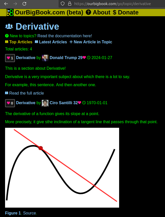
Figure 1. Screenshot of the "Derivative" topic page. View it live at: ourbigbook.com/go/topic/derivativeVideo 2. OurBigBook Web topics demo. Source. - local editing: you can store all your personal knowledge base content locally in a plaintext markup format that can be edited locally and published either:This way you can be sure that even if OurBigBook.com were to go down one day (which we have no plans to do as it is quite cheap to host!), your content will still be perfectly readable as a static site.
- to OurBigBook.com to get awesome multi-user features like topics and likes
- as HTML files to a static website, which you can host yourself for free on many external providers like GitHub Pages, and remain in full control

Figure 2. You can publish local OurBigBook lightweight markup files to either OurBigBook.com or as a static website.
Figure 3. Visual Studio Code extension installation.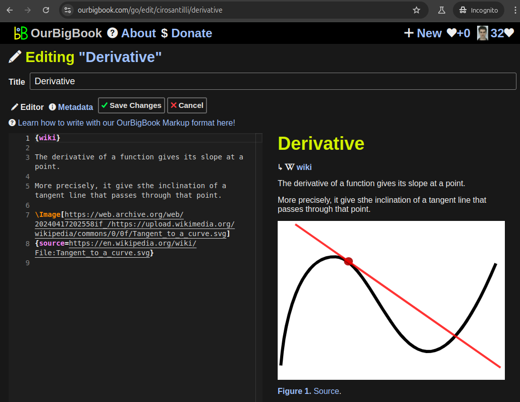
Figure 5. . You can also edit articles on the Web editor without installing anything locally. Video 3. Edit locally and publish demo. Source. This shows editing OurBigBook Markup and publishing it using the Visual Studio Code extension. 
- Infinitely deep tables of contents:
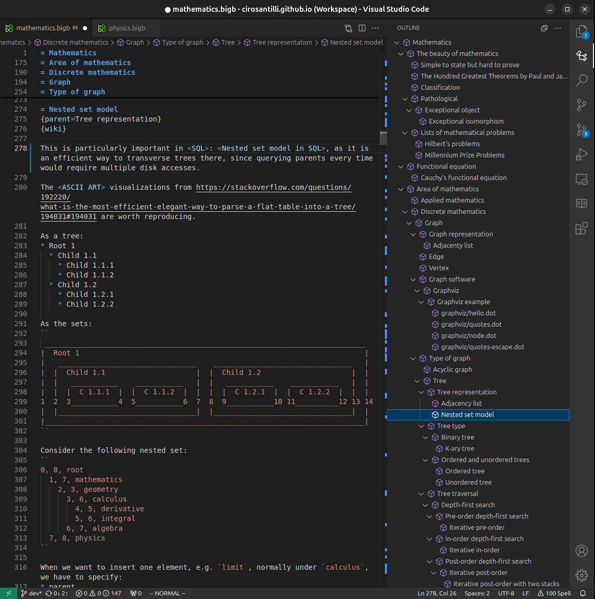

All our software is open source and hosted at: github.com/ourbigbook/ourbigbook
Further documentation can be found at: docs.ourbigbook.com
Feel free to reach our to us for any help or suggestions: docs.ourbigbook.com/#contact