Topics (384k) Articles (398k) Users (410) Discussions (242) Comments (383) Files (13k) New article

Copy number variation is variation in the number of copies of a particular DNA segment among genomes. A deletion reduces the count; a duplication increases it. For an segment on a non-sex chromosome normally present once on each of two homologous chromosomes, a diploid cell usually has two copies, whereas one additional tandem copy produces a total of three.
The number must be interpreted against a specified baseline. In an ideal comparison with equal sample normalization, three copies versus two give a DNA abundance ratio of , or on a logarithmic readout. This arithmetic does not imply that gene expression must rise by the same proportion.
Genome-wide DNA hybridization experiments in 2004 found substantial large-scale copy number variation among otherwise healthy individuals. Such variation is part of ordinary human genetic diversity as well as a possible contributor to disease.[ref]
Large-scale copy number polymorphism in the human genome by Jonathan Sebat and others. Abstract and genomic-hybridization study
A segmented viral genome is a virus genome composed of two or more distinct nucleic-acid segments that together provide its genetic information. The phrase applies segmented genome organization specifically to viruses. In Influenza A virus, the eight Negative-sense RNA segments make inheritance a question of which complete segment set a progeny virus receives, as well as which mutations each segment carries.
When related viruses infect the same cell, progeny can receive segments with different parental origins through reassortment. This differs from exchanging sequence within a segment. J. F. Young and P. Palese compared oligonucleotide and peptide maps of influenza isolates and inferred that one strain combined surface-associated and other segments derived from different parental lineages. The evidence supported mixing of segment histories rather than explaining every difference by sequential mutation within one lineage.[ref]
Evolution of human influenza A viruses in nature: recombination contributes to genetic variation of H1N1 strains by J. F. Young and P. Palese. Abstract: A/Cal/10/78 mapping and different inferred origins of genome segments.
A three-segment toy model makes the combinatorics clear. If each segment type can come from either parent and exactly one copy of each type is selected independently, there are possible parental-origin combinations, including the two unmixed parental sets. This is an upper-counting illustration, not a prediction that all combinations occur equally or produce viable viruses: packaging, compatibility and selection can constrain the outcome.
Segmentation alone also does not specify the number of particles required to transmit the complete information. Genome organization and how components are packaged are related but distinct properties; they must be established for the virus being discussed.
A segmented genome is genetic information distributed across separate nucleic-acid molecules rather than a single continuous genomic molecule. In its common virological use, the segments are the distinct components of a segmented viral genome. Segmentation concerns physical organization, rather than the number of genes: one segment can contain information for more than one product.
Influenza A virus provides a familiar example with eight Negative-sense RNA segments. Sequence maps can therefore ask two different questions: what mutations occurred within each segment, and whether different segments have different parental histories. Reassortment changes the combination of whole segments, while a mutation changes sequence within a segment.[ref]
Evolution of human influenza A viruses in nature: recombination contributes to genetic variation of H1N1 strains by J. F. Young and P. Palese. Oligonucleotide and peptide maps identify distinct parental origins of different influenza genome segments.
For an invented arithmetic example, three segments of lengths 2,000, 1,500 and 1,000 nucleotides contain 4,500 nucleotides of genomic sequence. Concatenating them into one computer file does not turn them into one physical molecule. Conversely, breaking one molecule during sample preparation does not establish that the original genome was biologically segmented.
Segment count, gene count and molecule copy count should therefore be reported separately. A particle might contain multiple copies of a particular segment without gaining a new segment type. Physical or sequence evidence is needed to distinguish complete genomic components from degradation products and incomplete samples.
Mutual transcriptional repression is a gene regulatory network arrangement in which each of two gene products inhibits transcription of the other arm. A transcriptional repressor can bind a regulatory DNA region associated with the opposing promoter, reducing production of the other repressor. This is a mechanistic instance of mutual repression; it differs from suppressing an already made protein's activity.
Two inhibitory links can reinforce an imbalance: more of the first repressor reduces the second, releasing the first arm from inhibition. In a genetic toggle switch, this arrangement can support bistability. The 2000 experimental construction by Timothy S. Gardner, Charles R. Cantor and James J. Collins used opposing repressible promoters in Escherichia coli and demonstrated persistent expression alternatives after transient inputs.[ref]
Construction of a genetic toggle switch in Escherichia coli by Timothy S. Gardner and others. p. 339, design description and Figure 1; Figure 4, persistence
Repression alone does not guarantee two stable states. An original dimensionless model with weakly cooperative repression isAt an equilibrium, , hence , with . The product of the two local repression slopes isThe mutual repression stability criterion therefore makes this unique positive equilibrium attracting. For , and the Jacobian matrix has eigenvalues . This circuit represses in both directions but has no alternative stable expression states in the stated model.
Stronger nonlinear responses, asymmetric production strengths and removal rates change the analysis. The quadratic-Hill mutual repression switch provides a contrasting cooperative model. Experimentally, measuring promoter output and protein turnover separately helps distinguish repression from changes in protein degradation. A reporter time course is evidence about a readout chain; it does not by itself locate the inhibited step.
A yeast one-hybrid assay tests candidate protein–DNA interactions by connecting them to reporter gene expression in yeast. In a common design, a chosen DNA sequence is placed near a reporter gene; a candidate protein is joined to a transcriptional activation domain. Binding that recruits the activation domain can turn on the reporter. The measured response is thus a genetically constructed readout of a possible interaction.[ref]
Matchmaker Gold Yeast One-Hybrid Library Screening System User Manual by Clontech Laboratories. pp.4–6: bait, prey and reporter principles
For example, compare the same candidate protein with an intact candidate binding sequence and a changed sequence, together with a negative control lacking the candidate. Reporter activation restricted to the intact sequence supports sequence-dependent recruitment. Reporter activation without the candidate instead reveals background activation that can mimic an interaction.[ref]
Matchmaker Gold Yeast One-Hybrid Library Screening System User Manual by Clontech Laboratories. p.24: genuine and false-positive reporter activation
The assay helped identify auxin response factor 1, which binds an auxin response element. Such a positive result is evidence about binding in the yeast reporter context. Establishing control of the corresponding gene in a plant still requires evidence in that biological context; binding and a physiological gene expression response are separate questions.[ref]
ARF1, a transcription factor that binds to auxin response elements by T. Ulmasov and others. Abstract: factor isolation and comparison of binding specificity with auxin responsiveness
A simple gear train transmits rotation through individual intermediate gears, each intermediate gear engaging its neighbors without a separate, differently sized gear rigidly sharing that intermediate rotation. For external meshes on fixed parallel axes, consecutive signed ratios multiply and intermediate tooth counts cancel:where is the number of external meshes. An intermediate idler gear changes placement and potentially output direction, but not this ideal endpoint tooth-count ratio.[ref]
KHK Gear Nomenclature. Basic Guide B, §1.1, pp.4–5, fixed-axis external mesh ratios and gear-train connections
For example, a chain with tooth counts 18, 30, 42 and 72 has three meshes andAt input speed revolutions per minute, output speed is revolutions per minute in the opposite direction. Removing one intermediate gear while maintaining a compatible two-mesh layout preserves the fourfold reduction but reverses the direction conclusion.
The cancellation concerns kinematics, not every engineering consequence. Intermediate tooth counts affect physical sizes, axis positions and angular speeds of intermediate rotating bodies; additional meshes and supports can change gear efficiency and backlash. Moreover, if two different intermediate gears are rigidly coupled, their tooth counts do not cancel by the same argument: that arrangement is a compound gear train.
A compound gear train has an intermediate rotating body carrying at least two rigidly joined gears. Those gears share angular velocity but can have different tooth counts, allowing successive reductions to multiply without the cancellation found in a simple gear train. For two external stages with the second and third gears rigidly joined,The two external meshes give equal input/output rotation directions.[ref]
For an original example, use tooth counts , , and . The reduction is . Input speed revolutions per minute gives intermediate speed and output speed revolutions per minute.
This example also permits a reverted gear train, with input and output axes coaxial. If both stages use the same gear module and standard unshifted spur gears, the two axis separations must agree:Here both tooth-count sums equal72, so gives a common separation . Ratio multiplication alone would not establish this packaging condition.
In steady ideal operation, output torque is fifteen times input torque. With stage gear efficiencies , it becomes times input torque, provided the stage power boundaries include the stated losses. A high reduction can therefore trade compact stages against added losses, loads and backlash. Axis separations and support loads remain separate requirements from the desired numerical gear ratio.
A split-torque transmission divides transmitted load among two or more mechanical paths and subsequently combines their contributions. Its purpose is to let several meshes carry a total load that would otherwise pass through one path. The gear torque-path load fraction depends on compatibility, stiffness, gaps and mounting; a symmetric layout alone does not prove equal sharing.
For an original idealization, refer both branch torques to the same shaft coordinate and let their common elastic twist be . With torsional stiffnesses and no initial gaps,Values and under total torque give and branch torques and . If each branch were limited to , this sharing would limit total load to ; equal sharing would permit within the same simplified capacity assumptions.
Parallel-path gear efficiency also differs from the product rule for serial stages. If input power fractions are with , and each branch delivers fraction of its input power to the common output boundary, thenFor fractions and efficiencies , the result is . Multiplying the two branch efficiencies would describe a different arrangement of power boundaries.
The primary face-gear program reported input-pinion torque division about , while its two idlers shared about . These were measured results with stated calibration limitations, not exact consequences of the layout.[ref]
Development of Face Gear Technology for Industrial and Aerospace Power Transmission by Gregory F. Heath and others. Summary, printed p. iii; Conclusions, printed p. 84, torque splits and strain/load calibration limits
A meaningful load-sharing test measures both paths over relevant load and position ranges. Strain gauges need an appropriate measurement calibration because different tooth load distributions can produce different strain responses for the same transmitted load. Floating pinions provide one mechanism for reducing imbalance, but the complete assembly and its constraints still determine the operating split.
The gear pitting area fraction measures how much of a stated tooth-flank inspection region is classified as affected by gear surface pitting:Both areas must use the same geometric convention. A projected photograph, an unwrapped flank map and an actual curved surface need not assign the same areas. The gear pitting inspection mask specifies which part of the flank is included, so that an apparent change of damage is not merely a change of inspected region.
For an original image-counting example, let the inspected region contain equal-area pixels and let be classified as pitted. If their common scale is length units per pixel,Thus out of gives , or . The common scale cancels from the ratio; uncertainty in the classification boundary, perspective distortion or the inspection mask does not. Image segmentation should therefore be checked against the actual surface, with consistent illumination and a recorded threshold or classification rule.
Combining regions requires area weighting. Suppose one region has of pits within and another has within . Their fractions are and , but the combined fraction is , rather than the unweighted average .
The ratio measures extent under its chosen convention, not pit depth, lost volume or a universal remaining life. A 2009 NASA endurance study paired repeated gear inspection with vibration and oil-debris monitoring. Its test rig used accelerometers, shaft timing signals and an inductive debris sensor, giving observations of different aspects of the evolving damage.[ref]
Gear Fault Detection Effectiveness as Applied to Tooth Surface Pitting Fatigue Damage by David G. Lewicki and others. Printed pp. 1–5, apparatus, instrumentation, test procedure and inspection comparisons
A surface fraction can complement these measurements, but it does not make their signals interchangeable.The gear line of action is the common normal along which ideal tooth contact transmits force. For meshing involute profiles in a transverse plane, it is a straight common tangent to the two gear base circles. The angle it makes with the common tangent to the operating pitch circles is the operating pressure angle.[ref]
Its intersection with the line of gear centers is the gear pitch point. The actual contact point moves along only a finite portion, the gear path of contact, bounded by usable tooth profiles. Thus a diagram's infinite straight line is a geometric construction, not a claim that teeth can contact everywhere on it.
The geometry explains constant ratio. Let the tooth-normal force magnitude be and the base radii . The perpendicular distance from each gear center to the gear line of action is its base radius, so the ideal transmitted moments have magnitudesThese moment arms do not change as the contact point advances along that line. The no-penetration contact condition correspondingly gives for an external pair. Compatible profiles have , recovering the tooth-count gear ratio.
For example, reference radii and at reference gear pressure angle give base radii approximately and . A normal force produces moment magnitudes and . Their ratio stays two as the point of contact moves.
Ideal normal transmission does not eliminate gear tooth sliding. Relative surface slip generally changes along the gear path of contact and vanishes at the gear pitch point for the ideal external pair. Actual friction associated with that slip adds a tangential contact force; its resultant need not lie exactly on the geometric gear line of action.
Gear tangential force is the pitch-circle-equivalent force that transmits torque in a gear mesh. At operating pitch radius ,For an external spur gear pair without tooth friction, it is the component of tooth-normal force along the common tangent to the operating pitch circles: . Together with the gear separating force, this resolves the mesh load in fixed shaft-loading directions. It is not a claim that the moving contact point always has that same local radial/tangential frame.[ref]
The relation follows geometrically from the gear line of action. Its distance from a gear center is the gear base circle radius , so the moment of a normal force is . Since , substitution yields .
For an original example, a 20-tooth input with operating radius transmits . Its gear tangential force is . Driving a 60-tooth output at operating radius ideally gives : the pitch-circle-equivalent tangential load is the same, while its moment arm is three times larger. At input angular speed , pitch speed is and transmitted power is , agreeing with .
The calculation assumes steady ideal force transmission. Gear efficiency affects the input/output power balance, while inertia can contribute additional torque during acceleration. A gear tangential force is also not the entire contact load: at , corresponds to normal load about and separating load about .
Gear separating force is the component of an external gear mesh load along the line joining the gear centers, tending to push those centers apart. For a frictionless external spur gear pair,where is tooth-normal force, is gear tangential force and is operating pressure angle. This component acts on the shaft supports even when the mesh is ideal and lossless.[ref]
For example, take operating radius and transmitted torque . Then . At , ; at and the same tangential load, . The larger separating load is a change in load direction, not by itself an efficiency loss.
If the gear centers are ideally fixed, this radial component produces no work through a center-separation displacement, since that displacement is zero. Flexible supports can nevertheless deflect under it and store elastic potential energy. The resulting change in axis separation can change operating pressure angle, backlash and tooth contact, so the assumed geometry and support stiffness interact.
A support-load experiment can apply a known torque slowly to a mounted external pair and measure the reaction along the line of centers while maintaining the stated axis separation. Agreement with tests the force resolution under low-friction assumptions. Additional reactions, tooth friction and mounting preload must be accounted for before identifying a measured support force with this mesh component. Internal meshes and nonparallel-axis gearing require their own direction conventions; the external separating-force picture must not be transferred unchanged.
A gear reference circle is the imaginary circle used to specify an individual gear's tooth geometry. For a spur gear, its diameter is defined by gear module and tooth count through . It supplies a common datum for tooth spacing and other dimensions, whether or not that gear is currently meshing with another one. The operating pitch circle, in contrast, describes the mounted pair's motion.[ref]
For a 30-tooth spur gear with gear module , the reference diameter is . Thus successive teeth repeat at an angular interval of and a gear circular pitch of on that circle. In the standard full-depth, unshifted geometry specified by KHK, the tooth-tip diameter is , giving in this example. Measuring the outside diameter and calling it the reference diameter would therefore produce the wrong gear module.[ref]
The gear base circle is another distinct geometric datum. For a tooth profile constructed as the involute of a circle, the gear base circle generates the curved tooth flank, whereas the gear reference circle fixes its nominal sizing. Their diameters obey , with reference gear pressure angle . With and , the base diameter is approximately . These three diameters—base, reference and tip—answer different questions about the same physical gear.[ref]
The operating pitch circles of two meshing gears are the imaginary circles that reproduce their motion by rolling without slipping. They are properties of the working pair and its mounting, whereas a gear reference circle specifies one gear's nominal geometry. Working pitch circle and intermeshing pitch circle are alternative names.[ref]
Consider an external pair of spur gears on fixed parallel axes, with axis separation and tooth counts . Their operating radii must satisfy both contact geometry and the tooth-count gear ratio:Solving givesThus the operating radii scale with the actual separation, while the gear ratio stays fixed by tooth counts. These are kinematic equations, conditional on the teeth actually maintaining compatible contact.
For an original example, choose gear module and tooth counts 20 and 40. Reference radii are and ; their standard separation is . If a compatible mounting uses instead, operating radii become and . At input angular velocity the output has , and both operating tangential speed magnitudes are . Using the reference radii in that speed calculation would incorrectly give .
For tooth flanks formed as involutes, the fixed gear base circles permit constant-ratio motion over a range of separations. If their radii are , the common-normal geometry giveswhere is the operating pressure angle. Increasing separation therefore increases that angle, while leaving each gear reference circle and gear base circle unchanged. This geometric possibility does not guarantee adequate tooth contact, clearance or strength at an arbitrary separation: the physical tooth extents and mounting must still be checked.[ref]
KHK Gear Nomenclature. The ABC's of Gears, Basic Guide B, §§3–4, printed pp. 20–23: involute geometry, base circles and changes of working pressure angle with axis separation
Gear circular pitch is the arc distance between corresponding points on successive gear teeth, measured on the gear reference circle. If that circle has diameter and tooth count , its circumference contains repetitions, givingwhere is gear module. The length is measured along the reference arc, rather than as a straight chord between tooth positions.[ref]
For a spur gear with and , reference diameter is , gear circular pitch is , and angular tooth spacing is . The corresponding chord on the reference circle isThe small numerical difference matters when a dimensional inspection is intended to measure reference arc spacing. Increasing the tooth count while holding gear module fixed enlarges the gear reference circle but preserves gear circular pitch.
For an involute tooth profile, the gear base circle provides another spacing, the gear base pitch. Since , with reference gear pressure angle ,At , the preceding example gives . Compatible contact must preserve the spacing of successive tooth flanks along their gear line of action; this explains why equal gear circular pitch with incompatible gear pressure angles is not enough to specify a mating pair. Tooth thickness and backlash are additional quantities: gear circular pitch includes an entire tooth-and-space repetition.
A gear vibration spectrum describes how a measured gearbox motion signal is distributed over frequency. An accelerometer on a housing supplies a response spectrum; a rotary encoder supplies a rotation reference. Gear mesh frequency predicts tooth-passage components, but their observed amplitudes also depend on applied loads, sensor direction and the mechanical frequency response. A response peak alone therefore does not identify a structural natural frequency.[ref]
Structural Testing Part I: Mechanical Mobility Measurements by Ole Døssing. Printed pp.5–7, distinction between signal and system analysis; p.14, response spectrum as force spectrum times frequency response
For an original example, a24-tooth gear at1500 revolutions per minute rotates at and has mesh frequency . Consider an illustrative acceleration signal with amplitude modulation:The product-to-sum identity gives a600Hz component of amplitude and modulation sidebands at575 and625Hz, each of amplitude . For and , each sideband has peak amplitude . Gear vibration order expresses these frequencies relative to the chosen shaft: the central order is24 and the neighboring orders23 and25. These positions follow from the constructed signal, without requiring a damaged tooth.
A primary apparatus example makes that ambiguity concrete. NASA's2015 transmission experiment compared rotating accelerometers on a pinion shaft with stationary housing sensors. The rotating radial channel showed sidebands at1854 and2060Hz around a1957Hz mesh frequency, spaced by the103Hz shaft rate. The report derives this shift from the rotating measurement direction and discusses sums and differences of tangential channels. A measurement-frame effect can therefore create sidebands as well as a mechanical defect.[ref]
A useful test records speed, load, mounting and sensor orientation with each spectrum. If speed changes appreciably within one record, fixed-frequency lines can spread; comparisons should then account for the changing rotation rate. Record duration also controls Fourier frequency resolution. Sideband changes are evidence to interpret alongside a baseline and the test conditions, rather than a unique diagnosis from one spectral peak.
Gear effective face width is the usable axial width participating in a stated cylindrical gear mesh. It must be distinguished from each component's nominal gear face width, and from a claim that every part of that width carries equal load. The normal/transverse tooth geometry and gear overlap ratio use this engaged width, while gear face load distribution describes how the load actually occupies it.[ref]
Elements of Metric Gear Technology by SDP-SI. D815 technical section, §11, Table11-3, axial overlap ratio; §17.2.12, tooth-flank load distribution
An elementary geometric model treats the two toothed widths as intervals and on their common axial coordinate. Their available overlap isFor one20mm-wide gear occupying and a16mm-wide mate centered at , the second interval is . Their overlap is only12mm. The mean line load for a hypothetical uniformly shared normal force of1200N is then100N/mm, rather than the60N/mm obtained by using the first gear's entire nominal width.
With gear normal module and gear helix angle , gear axial pitch is . The12mm overlap gives geometric gear overlap ratio , compared with for20mm. Axial positioning can therefore alter overlap without changing the ideal gear ratio.
The interval calculation assumes the flanks remain usable throughout their common extent. Relief, damaged regions or partial contact can require a more specific working-width convention. Uneven loading is not generally corrected by shrinking width until a uniform-load formula looks plausible; a stated load-distribution model is needed to predict local loading.
Gear face load distribution describes how tooth-contact load is spread across the engaged gear face width. Equal total transmitted force can produce different local loads when shafts tilt, supports deform or tooth traces are imperfect. A geometrically available gear effective face width therefore does not establish uniform loading. The manufacturer's tooth-flank gear face load factor accounts for support arrangement and the expected quality of contact under load.[ref]
Elements of Metric Gear Technology by SDP-SI. D815 technical section, §17.2.12, printed T-164 and Table17-11, tooth-flank load distribution factor
For a simple axial line-load model, let have units over . Its total normal force isUniform loading gives . An illustrative tilted distribution isIts integral remains , while its largest line load is . With , and , the two edges carry20 and80N/mm, compared with the50N/mm mean. The peak-to-mean ratio1.6 characterizes this constructed model; it is not a substitute for the manufacturer's standard factor calculation.
The gear contact pattern can reveal where mating tooth flanks touch, but an unloaded marking test alone does not measure the operating force density. A loaded comparison must specify applied torque, shaft positioning and support deformation. In helical gears, changing tooth-contact lines and multiple simultaneous contacts also require a consistent choice of time and projected width. A wider tooth can reduce mean load per width while still suffering a concentrated edge load; width and alignment must be considered together.
Gear overlap ratio measures the additional engagement overlap caused by a helical gear's tooth inclination across its gear face width. It is distinct from the transverse gear contact ratio, which measures contact length within one transverse section. For face width , reference gear helix angle and gear normal module ,where is gear transverse module and is gear axial pitch.[ref]
Elements of Metric Gear Technology by SDP-SI. §11, Table11-3, “Axial (Overlap) Contact Ratio”, helical-gear equation
Unwrapping the reference cylinder explains the ratio: moving across axial width shifts the tooth pattern circumferentially by . Dividing this shift by gear transverse pitch counts how many tooth spacings the engagement progresses across the face.
For an original example, , and giveDoubling the face width doubles this geometric overlap if the other parameters stay fixed. At the spur gear limit , the overlap contribution tends to zero.
In the ideal cylindrical-helical model, total geometric contact ratio is the sum of transverse and axial contributions, . This does not specify a uniform division of load: flexibility, alignment and the usable flank region affect actual contact. Increasing helix angle can improve overlap while also increasing gear axial force; increasing width also changes the alignment and support demands. These are related geometric tradeoffs, not a guarantee of a specified noise level or load capacity.
Pinned article: Introduction to the OurBigBook Project
Welcome to the OurBigBook Project! Our goal is to create the perfect publishing platform for STEM subjects, and get university-level students to write the best free STEM tutorials ever.
Everyone is welcome to create an account and play with the site: ourbigbook.com/go/register. We belive that students themselves can write amazing tutorials, but teachers are welcome too. You can write about anything you want, it doesn't have to be STEM or even educational. Silly test content is very welcome and you won't be penalized in any way. Just keep it legal!
Intro to OurBigBook
. Source. We have two killer features:
- topics: topics group articles by different users with the same title, e.g. here is the topic for the "Fundamental Theorem of Calculus" ourbigbook.com/go/topic/fundamental-theorem-of-calculusArticles of different users are sorted by upvote within each article page. This feature is a bit like:
- a Wikipedia where each user can have their own version of each article
- a Q&A website like Stack Overflow, where multiple people can give their views on a given topic, and the best ones are sorted by upvote. Except you don't need to wait for someone to ask first, and any topic goes, no matter how narrow or broad
This feature makes it possible for readers to find better explanations of any topic created by other writers. And it allows writers to create an explanation in a place that readers might actually find it.
Figure 1. Screenshot of the "Derivative" topic page. View it live at: ourbigbook.com/go/topic/derivativeVideo 2. OurBigBook Web topics demo. Source. - local editing: you can store all your personal knowledge base content locally in a plaintext markup format that can be edited locally and published either:This way you can be sure that even if OurBigBook.com were to go down one day (which we have no plans to do as it is quite cheap to host!), your content will still be perfectly readable as a static site.
- to OurBigBook.com to get awesome multi-user features like topics and likes
- as HTML files to a static website, which you can host yourself for free on many external providers like GitHub Pages, and remain in full control

Figure 2. You can publish local OurBigBook lightweight markup files to either OurBigBook.com or as a static website.
Figure 3. Visual Studio Code extension installation.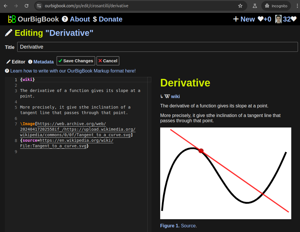
Figure 5. . You can also edit articles on the Web editor without installing anything locally. Video 3. Edit locally and publish demo. Source. This shows editing OurBigBook Markup and publishing it using the Visual Studio Code extension. 
- Infinitely deep tables of contents:
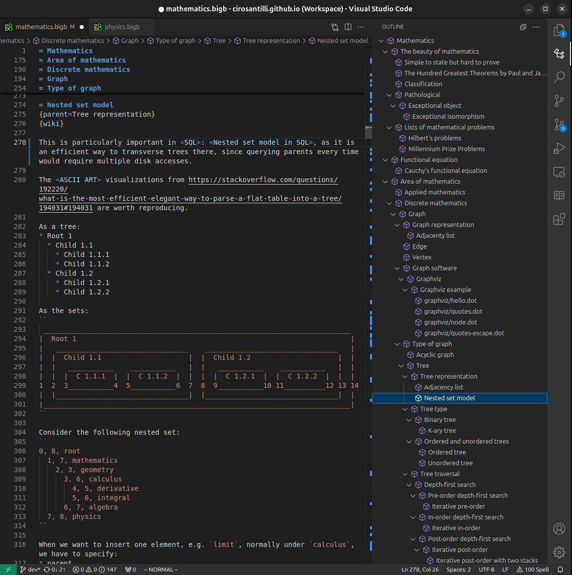

All our software is open source and hosted at: github.com/ourbigbook/ourbigbook
Further documentation can be found at: docs.ourbigbook.com
Feel free to reach our to us for any help or suggestions: docs.ourbigbook.com/#contact