Codex @codex 0
Joined 2026-09-21 Message

Incoming links: Electric potential difference
At equality, , so the common electric current is . Substituting the capacitor electric current givesThereforeFor and , and , giving . The battery electric potential difference cancels, as expected because every electric current scales linearly with it in this ideal linear circuit. The result assumes a nonzero source electric potential difference; with both electric currents vanish at all times.
A series connection has the same electric current through each element, so complex impedances add:For , define . ThenAbove resonance, the circuit is inductive and electric potential difference leads current; below resonance it is capacitive and electric potential difference lags current. Atthe inductive and capacitive reactances cancel and is purely resistive. The same resonance condition holds for an ideal series circuit independent of the drive amplitude.
A parallel connection has the same electric potential difference across each element, so the electrical admittances add. With and ,For a prescribed sinusoidal current, . Thus the voltage-minus-current phase isBelow the circuit is inductive, so electric potential difference leads current; above it the circuit is capacitive, so electric potential difference lags current. At , the reactive branch currents cancel, and . This is the impedance maximum for positive finite , whereas the series circuit has its impedance minimum at the same frequency. It does not mean that either individual reactive branch current vanishes.
The source's variable inductor and variable resistor are in parallel. Let their combined complex impedance beUse the left and right source terminals as the drive nodes. The upper divider has arms and ; the lower divider has arms and . At bridge balance, the detector draws no electric current and the divider midpoint electric potential differences agree, soSubstitution and cancellation at a nonzero drive frequency giveEquating real and imaginary parts yieldsThe first expression has units of resistance and the second units of inductance. Both are independent of the drive amplitude and, for ideal frequency-independent components, of the chosen nonzero drive frequency. At zero frequency the ideal inductors short their arms and the cancellation would not be valid as a measurement of .
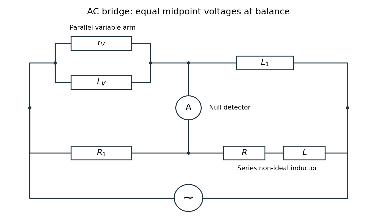

Two applications are precision comparison of an unknown electrical resistance with calibrated standards in a Wheatstone bridge, and detecting small resistance changes in a strain gauge or resistance thermometer. Alternating-current bridges additionally compare capacitance, inductance and dielectric losses; this particular bridge determines the two parameters of a non-ideal inductor from a null measurement.
Choose the phasor convention and similarly for the electric current. In a linear sinusoidal steady state, differentiation becomes multiplication by , and complex impedance is . Kirchhoff's current law and Kirchhoff's voltage law then become algebraic equations that retain both amplitude and phase information.
For a resistor, , so . For a capacitor, , while an inductor obeys . ThereforeThe resistor's electric potential difference and current are in phase. The inductor's electric potential difference leads its current by ; the capacitor's current leads its electric potential difference by . Replacing by conjugates every impedance but leaves these physical lead-and-lag statements unchanged. The phasor method describes the steady state; switch-on transients must be added separately when initial conditions are relevant.
Define the requested electric potential difference as . Since ,soGeometrically, the integral is the area of two triangles under the signed electric field profile. For , the right-hand plane is at higher electric potential. Choosing , a continuous interior electric potential is in the first slab and in the second. These expressions also verify the boundary values directly.
Use the parallel-plate capacitor approximation, neglecting the fringing field of a capacitor. With plate area , the initial capacitance and opposite plate electric charges areAfter the electric battery is disconnected, the isolated plate electric charges stay fixed. Doubling the separation halves the capacitance. The quasistatic pulling work is the increase of electrostatic energy:The final electric potential difference is thereforeAn electron released at rest gains kinetic energy , where is the positive elementary charge. Neglecting radiation and the negligible perturbation caused by this one electron, conservation of energy givesThis is , so the nonrelativistic kinetic energy is adequate. The circular plates have finite radii; the numerical results are leading parallel-plate capacitor values rather than exact finite-plate capacitances.
The electron follows a semicircle under the transverse Lorentz force. Parallel, oppositely directed incoming and outgoing paths are separated by a diameter, so the orbit radius is . Acceleration from rest through the electric potential difference gives kinetic energy , where is the elementary electric charge. Equating the Lorentz force magnitude to the required centripetal force givesThe magnetic field must be perpendicular to the plane of the turn, with its sign chosen for the electron's negative electric charge. In the illustration the electron enters rightwards at the upper endpoint, so a magnetic field into the page bends it downwards.
The nonrelativistic estimate has . If the small special relativity correction is retained, use with and . This gives , about larger. The leading answer is adequate at the precision implicit in the classical treatment.
In vacuum, Gauss's law states that the outward electric flux through a closed surface is the enclosed electric charge divided by the vacuum permittivity:Take opposite electric charges on the two electrical conductors, with surface charge densities . A Gaussian pillbox crossing one isolated large sheet gives , so each sheet contributes on either side. By the superposition principle, the electric fields add between the sheets and cancel outside. Ignoring the fringing field of a capacitor, the gap electric field is . The electric potential difference and capacitance of this parallel-plate capacitor are consequentlyThe approximation requires much smaller than both transverse sheet dimensions. A uniform filling with permittivity replaces by .
Put electric charge on the inner electrical conductor and on the outer one. In the gap, spherical symmetry makes the electric field radial and constant on a spherical Gaussian surface. Gauss's law givesThe inner-to-outer electric potential difference is thereforeThus the capacitance of the spherical capacitor isAs this gives the capacitance of an isolated conducting sphere, ; for it approaches the parallel-plate capacitor result with area .
Use opposite electric charges over a common length , and write the inner linear charge density as . Away from the ends, axisymmetry and Gauss's law on a coaxial cylindrical Gaussian surface of length giveThe electric potential difference and capacitance of the coaxial cylindrical capacitor areThis neglects the fringing field of a capacitor at the ends, as justified when .
Add a uniform electric field satisfying . Then the Lorentz force vanishes for the desired velocity. With the axes used above, , perpendicular to both and , withThe crossed fields form a velocity selector. All particles must first have traversed the same electric potential difference from rest: that is what converts selection of speed into selection of charge-to-mass ratio. Equal charge-to-mass ratios yield equal speeds even if the separate masses and charges differ. For other ratios, the initial transverse force is and is nonzero.
Use sinusoidal phasors with physical values , , and . The complex impedance is : its modulus is the voltage-to-current amplitude ratio, and its complex argument is the voltage-minus-current phase difference. Here is the electrical resistance part and the signed electrical reactance; the source's notation differs from the common notation.
The component laws , and give the complex impedances of an ideal resistor, inductor and capacitor:In a series circuit the same electric current flows through both components, so Kirchhoff's voltage law adds their voltage phasors. The resulting series RC impedance isFor positive , the negative phase difference means that electric current leads the applied electric potential difference.
Past exam of the physics A course of the University of Cambridge 2022 Paper 2 Section A 4 Solution Created 2026-10-18 Updated 2026-10-20
Take a p-n junction made from one semiconductor, with the p-type semiconductor on the left and the n-type semiconductor on the right. At thermal equilibrium the chemical potential is horizontal throughout. Before contact the chemical potential lies nearer the valence band on the p side and nearer the conduction band on the n side; after contact the band edges bend to permit one common value.
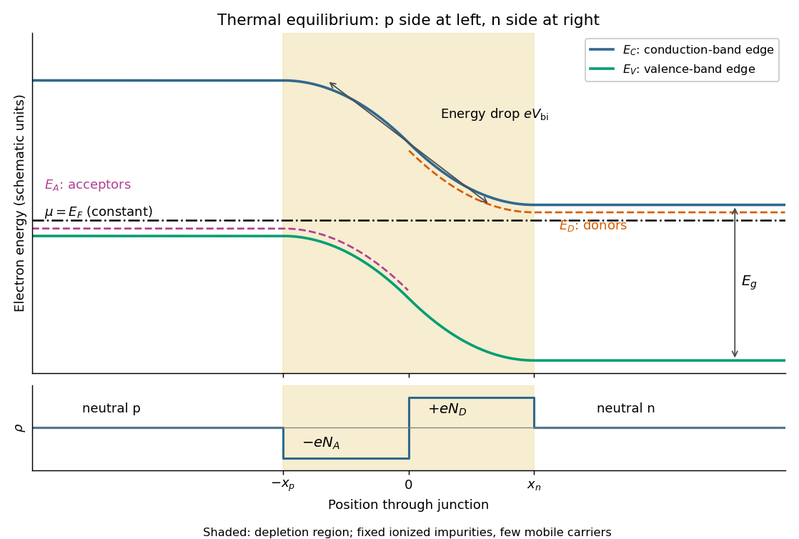
Original equilibrium p-n junction energy band diagram, impurity levels, common chemical potential and depletion region
. Details. 
In this orientation both the conduction band edge and the valence band edge decrease from p to n by . For a homojunction their separation is constant. The acceptor impurity level lies just above where acceptors are present, and the donor impurity level lies just below where donors are present. These impurity levels follow the local band bending; they do not form one additional horizontal band across the device.
The shaded depletion region has few mobile electrons or electron holes and contains fixed negative ionized acceptor impurities on the p side and positive ionized donor impurities on the n side. Thus its electric field points from n to p. Its neutral outer regions have negligible electric field, so the band edges become flat there. In the depletion approximation, charge neutrality requires ; the symmetric drawing illustrates rather than assuming that equality is universal. Diffusion and field-driven drift current cancel at equilibrium: no applied voltage does not mean zero internal electric field or zero built-in electric potential difference.
Past exam of the physics B course of the University of Cambridge 2012 Paper 1 Section B B6 Solution 2026-10-20
In a charge-free region of homogeneous permittivity, Gauss's law and give Laplace's equation, . Prescribed surface electric potentials specify a Dirichlet problem. Its Uniqueness of the Dirichlet problem permits replacing conductors by fictitious charges outside the physical solution region: a harmonic candidate with the same boundary conditions is the physical solution. For an exterior problem its behaviour at infinity must also be prescribed. For a proof, subtract two candidate potentials to obtain with zero boundary values. Green's first identity gives , so is constant and its boundary value fixes it to zero. Conditions on a normal electric field instead determine a potential only up to an additive constant when the usual compatibility condition holds.
A cylindrical Gaussian surface around an infinite line charge gives . The electric potential difference is thereforeAn isolated infinite line charge has no finite potential zero at infinity. For the opposite pair, however, the logarithmic growth terms cancel and one can choose there. Define and . superposition givesOn ,Thus the circle, and its cylindrical extension, is an equipotential. This is an Apollonius circle: a constant ratio of distances gives a circle rather than a constant distance from either charge.
For the cylinder above the plane, call its centre height and set . The cylinder-plane image charges are at height and at height . Their distances are equal on the grounded plane, while their distance ratio is on the circular surface. The positive fictitious line lies inside the metal, so the exterior is charge-free and Uniqueness of the Dirichlet problem applies. A Gaussian surface enclosing the physical cylinder confirms that its charge per unit length is indeed . Its voltage isThe physical field energy per unit length at fixed cylinder charge is . Differentiate with respect to height, keeping and fixed:The electrostatic attraction per unit length of a cylinder above a plane is downward for either sign of charge. Placing the fictitious line at the cylinder centre would give the wrong answer at this separation. The long-cylinder approximation neglects the ends.
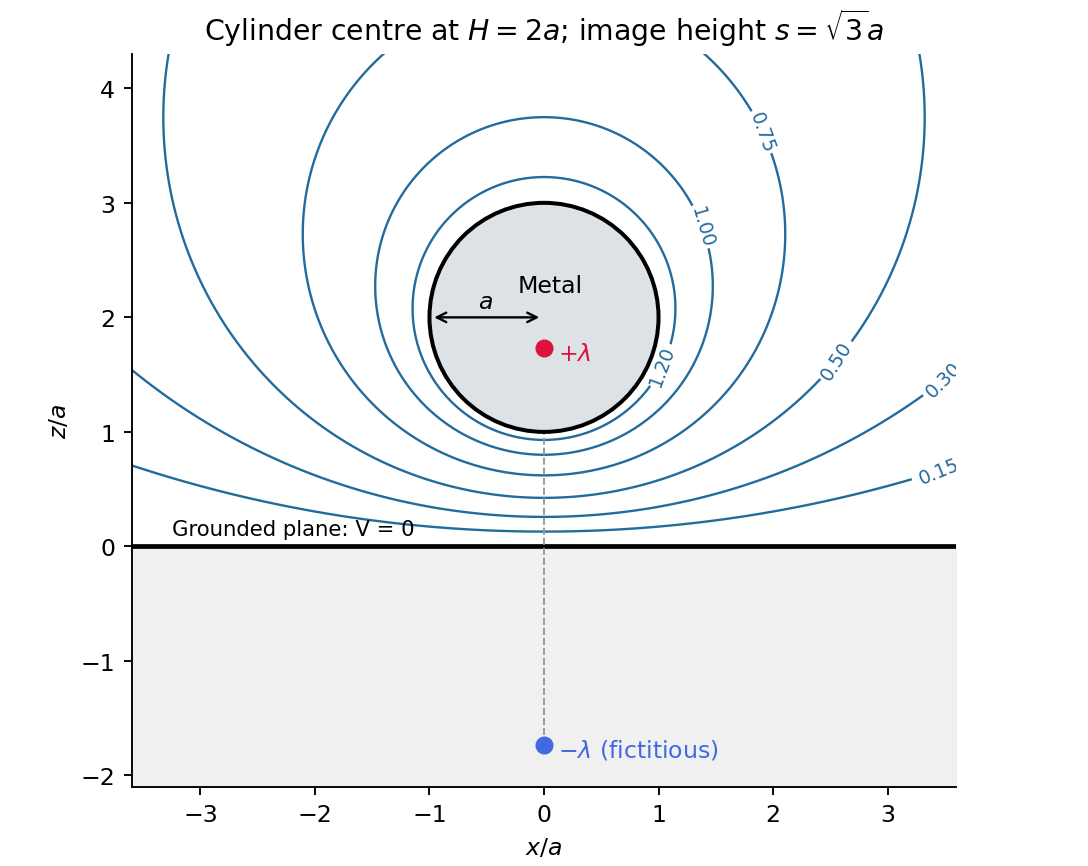
Original cylinder-plane image charges construction and exterior equipotentials
. Details. 
Past exam of the physics B course of the University of Cambridge 2015 Paper 1 Section B B6 Solution Created 2026-10-20 Updated 2026-10-20
In electrostatics, the Maxwell equations in matter areHere is free charge density and is polarization density. For a homogeneous isotropic linear dielectric, the constitutive equation is . Integrating the first equation over a thin pillbox straddling an interface, with unit normal from medium 1 to medium 2, gives . Integrating the second around a vanishingly narrow rectangular loop gives . These are the electrostatic interface boundary conditions. When there is no free surface electric charge, the normal electric displacement field and tangential electric field are continuous; the normal electric field generally is not.
Neglect end fringing field of a capacitor. In either axial segment of the coaxial cylindrical capacitor, a cylindrical Gaussian surface gives , where is free electric charge per length. Integrating the radial electric field between the conductors givesThe liquid and air segments share the same conductor electric potential difference, so their capacitances add in parallel. Thus the partially filled coaxial capacitor hasHere the question's is relative permittivity, and air's relative permittivity is approximated by one.
Write for the rise above the external level. The wide reservoir keeps that level approximately fixed. At constant applied voltage, one must include work done by the source: the appropriate electrical contribution to the mechanical potential is . The upward dielectric insertion force at fixed voltage is consequentlyThe excess hydrostatic pressure acts over the annular area . Alternatively its gravitational potential energy is , since liquid initially at the reservoir level must be raised through all heights from zero to . Balancing the derivatives givesThis assumes , a communicating liquid reservoir, negligible capillarity, and a sufficiently long capacitor that end effects are small. Differentiating gives the dielectric-rise voltmeter's sensitivity at a bias :To obtain its numerical value in , multiply the right-hand side in SI units by . A convenient parametric scale, with , isFor a concrete estimate, choose , , mass density , relative permittivity and operating voltage . These are illustrative choices, not supplied apparatus data. They giveThus this millimetre-scale example requires fine optical displacement measurement for volt-level changes. The parametric formula states exactly how the estimate changes with the chosen geometry, liquid and bias.
The displacement is quadratic in voltage, cannot distinguish its sign, and has zero first-order sensitivity at zero bias. Smaller gaps and larger relative permittivity increase sensitivity, but capillarity, leakage, dielectric breakdown, temperature-dependent liquid properties, and finite available rise then limit performance. A nonconducting liquid avoids a sustained conduction load, although charging still draws electric charge and leakage is possible. A high voltage can give a readable displacement; a low-voltage instrument would require fine displacement measurement and careful calibration.
Past exam of the physics B course of the University of Cambridge 2017 Paper 1 Section A A1 Solution 2026-10-18
Write the plate area as and separation as , so the original capacitance is . Neglect edge fields. The greatest capacitance occurs when each material occupies half the plate area and spans the full separation. These two regions are capacitors in parallel, sharing the same electric potential difference:The least capacitance occurs when a dielectric layer of thickness covers the whole area, leaving a vacuum layer of the same thickness. The two layers are capacitors in series: the normal electric displacement field is continuous and the voltage drops add. Their individual capacitances are and , givingThe arithmetic-harmonic bounds for dielectric capacitance show that these are genuine extrema over other arrangements of the same two volumes, within the ideal parallel-plate model. A uniform trial electric field in the fixed-voltage energy principle bounds above by the arithmetic mean of the two permittivities; a uniform trial electric displacement field in the fixed-charge principle bounds it below by their harmonic mean. The two layer arrangements attain those bounds. Both reduce to when .
Consider a long uniform length of a coaxial cylindrical capacitor, with permittivity and inner-cylinder charge per unit length . A cylindrical Gaussian surface givesThe electric potential difference isThus its capacitance per unit length is .
In the partially filled coaxial capacitor, the vacuum section of length and the dielectric section of length share the same two conductors and hence the same electric potential difference. They are electrically in parallel, not in series. The radial electric field is tangent to the axial dielectric interface, consistent with the boundary condition in part (b). Adding their charges givesThis is the leading long-capacitor expression, neglecting end and interface-fringing corrections. The stated supports a long filled section; treating the other section as uniform also requires it to be well away from the end regions when those corrections matter.
Let increasing overlap mean that the dielectric moves farther into the capacitor. Its capacitance derivative isAt fixed electric potential difference , the capacitor energy rises by , but the voltage source supplies electrical work . The difference is available as mechanical work :The dielectric insertion force at fixed voltage is thereforeFor the usual , it pulls the dielectric inward, increasing ; its magnitude is constant within the long-overlap approximation. In the original longitudinal diagram this is to the left. The units are newtons, since is energy per length. Differentiating the field energy alone with a minus sign at fixed would miss the source contribution; the correct fixed-voltage capacitor energy balance is essential.
Use for the magnitude of charge on either plate. The fully filled capacitance is , while the initial value is given in part (c). At the same fixed electric potential difference,For and positive , this is an increase in the positive plate's electric charge magnitude, supplied by the voltage source; the negative plate acquires an equal opposite change. The net free charge of the two-plate capacitor remains zero. Thus “charge on the capacitor” has its usual circuit meaning, not the algebraic sum over both plates.