Original solutions to the released 2017 paper. [ref]
https://www.whatdotheyknow.com/request/natural_sciences_tripos_part_1a/response/3284364/attach/3/FOI%202025%201239%20Hagendoorn%20materials.pdf?cookie_passthrough=1#page=17. Original public PDF, physical pages 17–24; questions on pages 18–24
The fluorite structure consists of a face-centered cubic lattice of calcium sites with all eight tetrahedral interstitial sites occupied by fluoride. In fractional coordinates of the conventional cubic unit cell, the calcium basis is , and fluoride occupies all combinations with . The projection therefore superposes two fluoride sites at each quarter-coordinate position. Labels in the original diagram give fractional depth along ; periodic boundary sites are displayed on both edges.
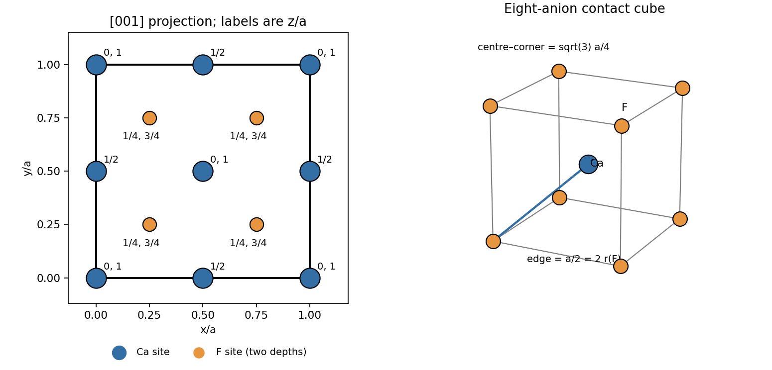
Original fluorite projection along the cubic z axis with fractional depths and the limiting anion-contact geometry
. Details. 
Counting shared sites gives calcium sites and eight interior fluoride sites: four formula units per conventional cell.
Each calcium cation has eight fluoride neighbours at the vertices of a cube: cubic coordination. Each fluoride anion has four calcium neighbours in tetrahedral coordination. Both unlike-neighbour Euclidean distances are , with the conventional cubic lattice parameter.
Apply the Goldschmidt packing principle at its limiting eight-coordinate geometry: the eight surrounding anions just touch one another and also touch the central cation. The anions form a cube of edge , so and . Eliminating givesEquivalently, . This is a limiting radius ratio rule, rather than a measured ionic-radius ratio. It does not assume that the calcium sublattice consists of mutually touching spheres: the calcium positions have face-centred cubic symmetry, but that symmetry alone does not specify which ions touch. A different construction with touching calcium spheres and fluoride just filling their tetrahedral interstitial sites would instead give ; that is the opposite contact limit, not the eight-coordinate anion-contact ideal used here.
Using the contact model of (b), and . Divide the volume of four cation spheres and eight anion spheres by to obtain the packing fraction:For one-radius cubic close-packed structure, face-diagonal contact gives , hence . The limiting fluorite value is lower than the one-radius close-packed value. Its two sizes, stoichiometry and eight-to-four coordination impose a different geometry: the fluoride sites form a simple-cubic array, and the calcium sites are too far apart for calcium–calcium contact. A face-centred arrangement of one species is therefore not sufficient to infer a close-packed whole crystal.
The actual ionic radii need not equal the limiting ratio, and electronic charge distributions are not rigid sphere boundaries. In the same unlike-contact hard-sphere model, put and use to getA cation somewhat larger relative to the anion than the limiting size opens gaps between the anions. Starting from and reducing modestly reduces this packing fraction; thus a lower value is expected for that departure from the ideal contact construction. The formula is not monotonic for all imaginable ratios, so no universal inequality should be inferred without specifying radii. Coordination-dependent ionic radii, polarizability, nonionic contributions to bonding, thermal expansion and point defects also limit the model. No numerical real-crystal packing fraction is determined by the supplied data alone.
A larger barium cation expands the fluorite structure and can widen the constrictions through which fluoride ions move. A plausible explanation is therefore a smaller ionic migration barrier and greater fluoride mobility. In a simple dilute-carrier description, , or when an uncorrelated Nernst-Einstein relation applies. fluoride vacancies and interstitial defects, including those generated as Frenkel pairs, provide possible carriers.
More open migration pathways can raise the conductivity, but ion size by itself is not a proof: defect formation free energies set , migration free energies set mobility, and correlated hopping can alter the simple relation. A controlled comparison would use crystals with comparable impurity content, thermal history and electrode conditions, and measure conductivity over temperature to separate plausible activation behaviour from extrinsic defect effects.
Take the longitudinal scalar piezoelectric coefficient appropriate to the load and electrode direction. For a uniformly stressed slab of face area and thickness , the source charge is . Its capacitance is , so the ideal initially uncharged, electrically isolated sensor givesThe sign depends on the poling direction and electrode convention. Equivalently, the incremental constitutive law is ; an ideal open circuit keeps free electrode charge, hence , fixed and gives . area cancels because both generated charge and capacitance scale with area. Thickness does not cancel: the material comparison is through only when geometry is fixed. Here must be the relative permittivity under the relevant mechanical and frequency conditions.
For identical thicknesses, compare using the supplied coefficients:for barium titanate, lead zirconate titanate and quartz respectively. Thus barium titanate, then lead zirconate titanate, then quartz is the increasing voltage sensitivity of a piezoelectric sensor order. A large charge coefficient alone does not guarantee a large voltage: the large permittivity of a ferroelectric also increases its capacitance.
For quartz, and . With , the load and stress are and . ThereforeAs a check, and give the same result. This is the ideal maximum open-circuit change on applying the load. Input capacitance reduces it to , while finite leakage makes it decay: it is not a guaranteed permanent DC output.
The sensor must survive the stress range and repeated loading without fracture, fatigue or excessive mechanical compliance. The tensor character of the piezoelectric coefficient makes crystal orientation important; a ceramic's poling quality and domain stability also matter. Compare linearity, hysteresis, reproducibility, aging and the usable frequency bandwidth, including resonance and dynamic response.
Electrical design is equally important: leakage resistance and readout input impedance determine low-frequency loss, and cable/input capacitance loads a voltage output. A charge amplifier may favour a different material ranking from a passive open-circuit voltage measurement. temperature changes can alter the coefficients, produce a pyroelectric signal in a polar material and depole a ferroelectric near its transition. Humidity, electrode bonding, electrical breakdown, manufacturability, cost and environmental constraints such as lead content also affect a practical choice. Calibration should separate applied stress from temperature drift and readout loading.
ferroelectric poling is essential. An initially unpoled ceramic has differently oriented crystal grains and domains whose charge responses largely cancel. An applied electric field favours suitably oriented domains and leaves a remanent macroscopic polarization after removal; it does not rotate all crystal grains into a single crystal.
In the linear coefficient model the added source polarization isThis is the stress-generated contribution at fixed electric field, equivalent to the short-circuit charge per face area. Under open-circuit conditions the induced field supplies an opposing dielectric contribution, so ; the source quantity must not be confused with a change of total free electrode charge. For scale, room-temperature single-domain barium titanate has spontaneous polarization of order : the calculated increment is about of that value, a small response rather than wholesale reversal of the spontaneous polarization.[ref]
Dielectric and optical properties of melt-grown BaTiO3 by S. H. Wemple and others. pp. 1799–1800, spontaneous-polarization measurements and temperature dependence
For the requested displacement estimate, assign the whole additional dipole moment of one cell to movement of its single ion relative to a fixed background. Then , givingThis formal-charge estimate is only an equivalent displacement: real polarization changes involve oxygen and barium displacements, electronic polarization and Born effective charges, as well as possible domain-wall motion. The coefficient supplied for the ceramic cannot uniquely determine an actual microscopic titanium trajectory.
A heated cathode emits electrons, accelerated through a potential difference onto a metal target. Deceleration produces a bremsstrahlung continuum with ; inner-shell ionization followed by electronic relaxation produces characteristic lines. The pictured instrument is consistent with the copper-target TEL-X-Ometer used for teaching diffraction. Its copper radiation has wavelength about , comparable with atomic plane spacings. A nickel filter preferentially suppresses copper , while slits collimate the beam; filtering does not remove every continuum photon.
A Geiger-Müller counter converts photon-induced gas ionization into countable electrical pulses. A scintillator with photomultiplier is another detector option. A detector-arm scan records count rate against scattering angle; coupled crystal rotation preserves the usual reflection geometry. These instrument features are documented by its manufacturer.[ref]
TEL-X-Ometer X-Ray System Manual by Joseph Dohm. Sections 3.5–3.6 and 7.1: crystal/detector geometry and detection; section 4.6: copper characteristic wavelengths
For the numerical calculations below use , explicitly identifying the characteristic line assumed. The photograph alone does not give a measured wavelength or angular travel limit; conclusions depending on these parameters are stated conditionally. A different selected line changes the angles but not a crystallographic extinction.
For a cubic crystal, and first-order bragg diffraction requires . The face-centred lattice sum isIt is four if are all even or all odd, and zero for mixed parity. With the NaCl basis displaced by , the allowed amplitudes are , up to the arbitrary choice of origin/species. Both allowed parity classes survive because the two ionic scattering factors are not identical. Intensities depend on , geometry, absorption and scattering vector.
There are three separate tests: nonzero structure factor, accessible Bragg angle, and accessible plane orientation. In a symmetric reflection scan the scattering vector is normal to the specimen face, selecting the surface-parallel family and its allowed orders. Other families need a different mounting, independent orientation control or transmission/another facet. The original diagrams distinguish these geometric requirements; angles in the reciprocal-space panel are between plane normals, not Bragg angles.
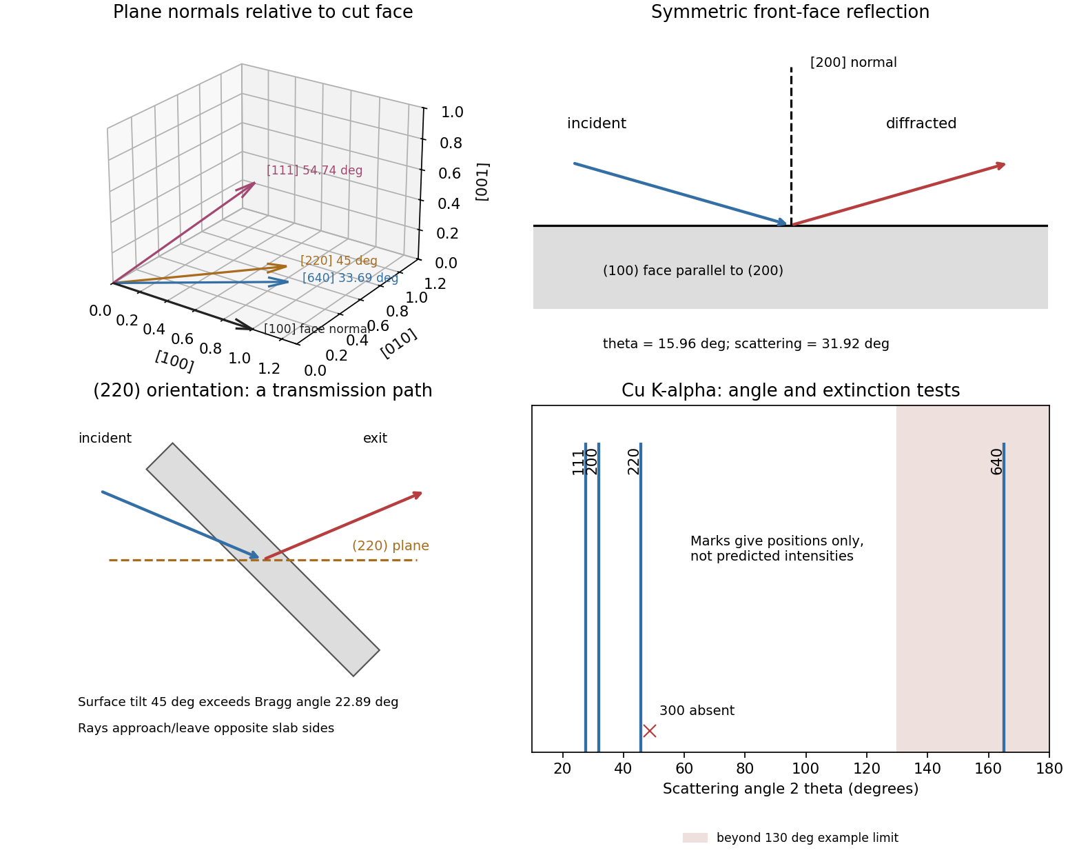
Original diffraction diagrams separating orientation, scattering angle and reflection versus transmission access
. Details. 
The even indices give an allowed reflection. Its spacing is , andThe planes are parallel to the cut face, so the ordinary coupled reflection scan reaches them directly. This is an easy, strong peak, with the two ionic amplitudes adding rather than subtracting.
The reflection is allowed, with and . Its odd-parity amplitude is proportional to , generally weaker than the corresponding sum. Its normal makes with the surface normal.
It is therefore not obtained in the ordinary symmetric scan of that face, despite its modest Bragg angle. In a usual edge-aligned cubic mounting its normal also has an out-of-horizontal-plane component. A suitable multi-axis reorientation, or a crystal cut with a face, makes the reflection accessible; a thin specimen in transmission or a powder experiment is another route. Tilting the scattering vector does not by itself ensure front-face reflection: because exceeds , incident and outgoing rays for that highly asymmetric orientation cannot both lie outside the same flat face. A suitable specimen shape/transmission path or recut face is needed.
The indices have mixed parity, so the face-centred lattice sum vanishes: the ideal NaCl reflection is systematically absent. A smaller wavelength, a larger detector range or an extra rotation axis does not remove that extinction. A nominal peak there could reflect another wavelength/reflection, multiple diffraction, another phase or broken ideal translational symmetry; it would not be an ordinary kinematic reflection of ideal NaCl. The allowed peak is a different reciprocal-lattice vector, not a recovered peak.
The all-even reflection is allowed. Here and . Its normal is from and can lie in the horizontal scattering plane in an edge-aligned mounting. Nevertheless it is not parallel to the large face, so the ordinary coupled symmetric scan misses it.
Independent sample rotation can bring the normal onto the Bragg bisector, but there is an important specimen constraint: is less than the surface inclination. One ray then traverses the slab rather than emerging from the incident face. Thus a thin transmission specimen or access through another face can permit detection after suitable remounting, whereas a thick absorbing slab in front-face reflection is unfavourable. A -cut crystal allows a straightforward symmetric measurement, and a powder specimen supplies the needed orientations. Unlike , no extinction prohibits it; whether the original portable mounting can reach it depends on independent rotation, holder clearance and the transmitting path.
The all-even indices are allowed, but is small. copper givesThis is near backscattering and outside an ordinary portable instrument whose arm reaches only about . The numerical angular limit should be checked on the actual model; the mathematical requirement is that its maximum reach . It also requires a normal inclined to , so the coupled surface-normal scan is insufficient. atomic scattering factors are smaller at this larger scattering vector.
A suitable high-angle, independently orientable diffractometer could detect it. A shorter selected wavelength can instead reduce the angular requirement: with , , while orientation still needs to be set appropriately. If exceeded there would be no first-order Bragg solution at all. The tube continuum and other characteristic lines must therefore be distinguished from the specifically calculated copper peak.
Randomly oriented crystallites supply planes with their normals in each required scattering-vector direction. Of the five families considered, , and can therefore give accessible copper powder peaks; remains absent and remains beyond a roughly detector limit. Other allowed families also appear if their Bragg angles lie inside the instrument range; orientation averaging does not restrict the pattern to these five examples.
Only a small fraction of randomly oriented crystal grains satisfy the Bragg condition for a given detector setting, and each family scatters around a cone rather than concentrating all its intensity into one single-crystal spot. A narrow detector aperture therefore receives a relatively weak signal from a small powder specimen compared with a well-oriented large single crystal. Adequate crystal grain statistics, longer counting, suitable powder packing and detector acceptance matter. The odd-parity peaks additionally involve the difference of ionic scattering factors. No absolute single-crystal/powder intensity ratio follows without illuminated volumes, absorption and instrumental geometry.
The close-packed planes of a cubic close-packed structure are , with stacking. Each layer is a triangular array; the third layer occupies the remaining set of hollows rather than returning above the first.
The basal close-packed planes of a hexagonal close-packed structure are in four-index Miller-Bravais index, or with three hexagonal indices. Their stacking is : alternate layers return above the same lateral positions.
At fixed transformed volume, an equilibrium solid-state precipitate seeks a low total free energy, including the orientation-dependent interfacial energy and elastic strain energy associated with misfit and applied stress. Low-energy interface orientations occupy large faces. The Wulff construction captures surface-energy anisotropy when strain and other contributions can be neglected; a solid-state precipitate generally also pays coherency strain energy, and its optimum shape can change with size.
During formation, growth kinetics and diffusion may prevent the equilibrium shape being reached. Coherent, semicoherent and incoherent interfaces have different bonding and defect structures, so their energies and attachment rates differ. The disc shape is consistent with much cheaper broad faces than edges, but morphology alone does not uniquely measure the energies or prove equilibrium.
Choose the orientation relation with aligned close-packed rows, for example . The two phases then share matching triangular layers at the broad faces. The stacking changes from to across the phase region, so broad coherent crystal interfaces can be made by a local change of stacking, with small mismatch if the in-plane atomic spacings are similar.
At the cylindrical edge, different layer sequences terminate against one another. Registry cannot generally be maintained everywhere, so ledges, stacking defects and possibly misfit dislocations are needed; this interface is less coherent and often more costly. Thus a low-energy basal/ face and a higher-energy edge favour a thin plate. An ideal same-element stacking change need not imply zero edge energy or exactly zero face energy.
The disc volume is , the combined area of its two flat faces is , and its cylindrical edge area is . With the signed bulk driving term per volume,For favourable transformation is negative and the interfacial terms are positive. This classical nucleation theory expression neglects a separate elastic term; if coherency strain is important, its appropriate energy must be added or included explicitly in the effective volume term. has energy units, whereas here has energy-per-volume units.
Along the stipulated fixed-aspect-ratio pathway, substitute before differentiating:The nonzero stationary diameter isComparison with the stated diameter gives , hence , provided is nonzero. This is a plate-like shape, qualitatively consistent with the cheaper broad coherent faces. For negative , substitution shows the stationary point is a maximum along this size pathway, as required for a nucleation barrier.
A useful distinction is that this calculation holds shape fixed. Minimizing the interface energy at fixed volume separately gives for the cylindrical model; if the selected aspect ratio is also an equilibrium shape, it would require . The given critical-diameter relation alone does not otherwise determine that energy ratio. In the degenerate zero-face-energy limit the coefficient comparison cannot determine .
Measure from the clamped end and let downward deflection be positive. In the small-slope elastic beam model, the bending moment has magnitude and . Integrating with givesFor the rectangular cross-section, , and thereforeRequiring with yieldsThis calculation neglects beam self-weight as stipulated, and also transverse shear deformation and geometric nonlinearities. The end slope at the limit is , so the small-slope approximation is reasonable for the intended estimate. Meeting a stiffness specification alone does not establish safe strength or fatigue life.
The optimum axial-stiffness arrangement has continuous straight fibres parallel to the beam axis with good fibre–matrix bonding. For a common axial strain , force balance on a section gives . Divide by total area and by to obtain the longitudinal rule of mixtures,This is an isostrain upper idealization, consistent with the Voigt elastic approximation. The glass fraction required by the deflection constraint isAbout 95.8% glass by volume is impractical for an ordinary glass-fibre/polymer board. It leaves little matrix for wetting, load transfer and defect tolerance. Identical circular parallel fibres pack at most in a regular hexagonal array; even that zero-void ideal gives only . Polydisperse or noncircular fibres can change that geometric limit, so it is not an absolute theorem about every possible composite. Waviness, voids, incomplete bonding and nonaxial fibres further reduce the achievable modulus. A thicker section or a stiffer reinforcement is a more plausible design change.
Let be the carbon-fibre volume fraction of the whole composite. Then and . Under the same longitudinal rule of mixtures,Setting givesThus carbon occupies 17.8% of the complete composite, or about of its total fibre volume. The resulting total fibre fraction is much more plausible than the glass-only estimate. This remains an ideal stiffness calculation requiring aligned, effectively loaded fibres; strength and fatigue checks are separate.
Make the implicit fixed-crack-geometry assumption explicit by writing , where is common to the compared specimens and includes the crack-size dependence needed for dimensional consistency. linear elasticity givesThe appropriate materials merit index is therefore , or its monotonically equivalent square root. This comparison holds crack geometry and the brittle-failure model fixed; changing crack sizes or yielding before fracture changes the selection problem.
The maximum recoverable elastic energy per initial volume is the area under the linear stress–strain curve up to failure:Using gives , so maximize for the fixed geometry. has units of energy per crack area, while has energy per specimen volume; the geometric factor supplies the necessary inverse length. The cancellation of is why the strain-maximizing index from (a) is not appropriate here.
TODO: user-deferred biology. This printed subpart is intentionally deferred under the current nonbiology-only scope.
TODO: user-deferred biology. This printed subpart is intentionally deferred under the current nonbiology-only scope.
TODO: user-deferred biology. This printed subpart is intentionally deferred under the current nonbiology-only scope.
TODO: user-deferred biology. This printed subpart is intentionally deferred under the current nonbiology-only scope.
TODO: user-deferred biology. This printed subpart is intentionally deferred under the current nonbiology-only scope.
TODO: user-deferred biology. This printed subpart is intentionally deferred under the current nonbiology-only scope.
A heat engine must reject some absorbed heat to a colder reservoir. For heat addition and rejection at absolute temperatures and , the Carnot bound isAt fixed , increasing increases this upper limit and can increase useful specific work in an appropriately designed gas-turbine cycle. Thus a higher hot-side temperature permits more efficient conversion of heat to work, rather than merely heating the exhaust. Real combustion occurs over a temperature range, and actual efficiency also depends on pressure ratio, losses and cycle design: peak temperature alone does not determine it. The materials incentive is to sustain higher turbine inlet temperatures while maintaining strength, oxidation resistance and acceptable creep life.
At turbine operating temperatures, grain boundaries provide paths for rapid diffusion, grain-boundary sliding and cavity formation, encouraging creep rupture. A single-crystal turbine blade removes these boundaries, especially boundaries unfavourably oriented across the tensile load. It retains dislocations and can still creep; eliminating boundaries is useful in this high-temperature regime even though fine crystal grains can strengthen other materials at lower temperatures.
Use directional solidification of the cast alloy through a controlled thermal gradient. A suitably oriented seed or a narrow grain selector lets one crystal survive and grow into the blade mould while suppressing competing nucleation. A spiral selector is a common way to exclude competing crystal grains. The blade is generally oriented near a axis for the intended anisotropic properties. crystal grain selection is experimentally verified by orientation mapping, rather than assuming a directionally elongated casting is automatically a single crystal.[ref]
Grain Selection in a High-Efficiency 2D Grain Selector During Casting of Single-Crystal Superalloys by Xintao Zhu and others. Sections 1–3, directional casting, selector geometry and electron-backscatter diffraction of surviving grains
The nickel-rich matrix is a disordered substitutional solid solution on a face-centered cubic lattice. The ordered phase has the L12 structure, approximately : aluminium occupies cube corners and nickel occupies face centres. Its occupied-site geometry is often called ordered FCC, but its chemically labelled Bravais lattice is primitive cubic, with a four-atom basis. A face-centre translation exchanges chemical sublattices and is not a symmetry of the ordered crystal.
Each Al atom has twelve nearest-neighbour Ni atoms at Euclidean distance . Each Ni atom has twelve nearest neighbours too, but these are four Al and eight Ni. The chemical distinction matters for slip. In disordered , the shortest perfect Burgers vector isFor the ordered primitive cubic translation lattice, the shortest order-preserving perfect vector isThis does not imply that slip must dominate. A vector must lie in a favourable glide plane and have an accessible core structure and activation stress. Matrix dislocations commonly glide on systems. A single passage through leaves an antiphase boundary; a second matching passage restores order, giving total vector . Such a superdislocation has a longer total vector than , yet its constituent dislocations can move on the favourable close-packed planes and interact with the matrix. Paired motion balances line and antiphase-boundary energies, so the shortest abstract lattice translation alone does not select the active slip system.[ref]
Nickel based superalloy: dislocation structure by H. K. D. H. Bhadeshia. explanation of matrix translations, ordered-phase antiphase boundaries and paired dislocations
The main strengthening architecture is a high volume fraction of fine, thermally stable ordered gamma prime phase precipitates in the ductile nickel-rich matrix. Their nearly matching crystal parameters allow coherent crystal interfaces, but coherence does not make them transparent to a moving dislocation: cutting disrupts chemical order and costs antiphase-boundary energy. Pairing of cutting dislocations and their interactions with narrow matrix channels raise the stress needed for deformation. For particles that are bypassed, bowing and high-temperature climb are also impeded by the precipitate spacing and interface dislocation structures.
coherency strain and differences in elastic response provide additional obstacles. Refractory substitutional solutes contribute solid-solution strengthening and can slow diffusion-controlled deformation. Single-crystal manufacture suppresses grain-boundary creep and grain-boundary cavitation. Together these mechanisms permit useful strength at temperatures where an unstrengthened nickel matrix would deform much faster. Protective oxide scales and coatings preserve load-bearing material against environmental attack; they complement, rather than replace, the internal strengthening mechanisms.
A concrete microscopic observation is the paired dislocation loops around fine precipitates in the Cambridge C263 creep micrograph: the observed defect structure supports the importance of precipitate–dislocation interactions, though one image does not by itself separate every strengthening contribution.[ref]
Nickel based superalloy: dislocation structure by H. K. D. H. Bhadeshia. creep-tested C263 micrograph and accompanying paired-loop interpretation
In-situ diffraction during stress-jump tests of a rafted AM1 single crystal also resolves evolving load partition and deformation in matrix channels, demonstrating why channel width and interface interactions matter.[ref]Dislocation Densities and Velocities within the γ Channels of an SX Superalloy during In Situ High-Temperature Creep Tests by T. Schenk and others. abstract, Sections 2–4: transmission diffraction, loading transients and channel-deformation analysis
Long exposure can coarsen or change the precipitate morphology and alter channel widths, so high strength is conditional on temperature, time and microstructural stability. Articles by others on the same topic
There are currently no matching articles.