Topics (384k) Articles (398k) Users (410) Discussions (242) Comments (383) Files (13k) New article

A medical physicist applies physics to measurement, modeling and instrumentation in medicine. Typical scientific work concerns radiation therapy, medical imaging and nuclear medicine, together with research and teaching. A medical physicist connects an instrument's readout with a defined physical quantity, tests the assumptions behind that conversion and evaluates its measurement uncertainty. The professional role includes investigating equipment performance and consulting on the physical basis of diagnosis and treatment.[ref]
What do Medical Physicists Do? by the American Association of Physicists in Medicine. Clinical Service & Consultation, Research & Development and Teaching
An ionization chamber illustrates the reasoning. Ionizing radiation generates mobile charges in a chamber; the collected electric charge is an instrument reading, not already an absorbed dose. In a stipulated reference setup, let be the measured charge, a matched background reading and a calibrated conversion coefficient. A simple measurement model isThe coefficient is valid only for the conditions covered by its measurement calibration. The IAEA describes the documented chain linking reference laboratories, calibrated instruments and their users; moving a coefficient into a different beam or geometry requires an appropriate justification.[ref]
Medical Physics and Dosimetry by the IAEA. One-page overview: absorbed-dose measurement and calibration chain
For an original arithmetic example choose , and . The model gives . Ignoring that background gives . These stipulated detector values illustrate background subtraction and dimensional conversion; they do not specify a treatment or a clinical beam-calibration protocol.
Suppose the corrected charge has standard uncertainty , and independently . First-order uncertainty propagation givesA covariance term must be included if the input estimates are correlated. The medical physicist's task includes establishing whether that model describes the actual readout, rather than just multiplying a displayed number by a remembered constant.
A water phantom provides a reproducible medium for measurement comparisons; measurements at specified positions can test a beam model without equating the test object with every patient's anatomy. In medical imaging, analogous comparisons use known geometry or material properties to assess image formation and instrument response. Repeated equipment checks test constancy, while comparison against calibrated references tests accuracy. Research, reference measurements and clinical implementation therefore involve connected scientific questions with distinct evidence.
A water phantom is a water-filled reference object used to measure how a radiation field deposits energy under specified, reproducible conditions. In radiation dosimetry, a detector can be positioned at controlled depths and lateral locations inside the water. The measured quantity is related to absorbed dose in that reference medium; the tank is not a complete anatomical model of a patient.[ref]
Absorbed Dose Determination in External Beam Radiotherapy by the International Atomic Energy Agency (2000). Section4.2.3, Phantoms, printedpp.39–40
The surrounding medium matters physically. Photons and charged particles can scatter, attenuate and transfer energy before it is collected locally. An empty holder, a small isolated water sample and a large water tank need not produce identical fields at a detector. The named IAEA edition treats both water as reference material and the margins of scattering material around a measurement region. A water-equivalent material must be compared in relevant absorption and scattering properties, not identified by similar bulk density alone.[ref]
A practical apparatus combines a tank, a positionable ionization chamber or another characterized detector, a readout and a way to define the water surface. For example, PTW's MP1 description specifies one-dimensional detector travel, levelling supports and fill marks. Its depth-positioning mechanism supports a depth-dose curve; one mechanical coordinate is not itself a full three-dimensional scan.[ref]
MP1 water phantom by PTW. General Information and Key Features
An original position-error model shows why the reference coordinates matter. At a fixed depth, stipulate a lateral absorbed dose profileA displacement from changes the dose ratio toThe same displacement from the centre gives . Thus the same absolute positioning error can produce about variation on a gradient and only at the centre of this stipulated profile. These are mathematical examples, not measured beam characteristics or equipment accuracy claims.
An ionization chamber also samples a finite sensitive volume, so detector volume averaging can differ from a point value of . Converting its collected electric charge to absorbed dose requires the applicable measurement calibration and measurement model, as described in medical physicist. Changing the tank position does not remove a detector's intrinsic spatial response.
Comparisons should therefore identify the water surface, detector reference point, irradiation geometry, water conditions and background treatment. The IAEA discussion of waterproof sleeves and chamber positioning illustrates why the detector and its surrounding hardware are part of the measurement configuration.[ref]
Fracture mechanics studies the initiation and growth of cracks under loading. It connects a defect's geometry with the local driving force for crack extension and the material's resistance. A component's average stress alone cannot describe the concentration of deformation near a crack tip.[ref]
In linear elastic fracture mechanics, a mode-I stress intensity factor often has the form , where is a specified crack dimension and accounts for geometry. Doubling increases by at fixed nominal stress. Comparing the appropriate intensity with measured fracture toughness is meaningful only when the loading, geometry and small-scale yielding assumptions of the model apply.
A machine is a physical system arranged to transmit or transform forces, motion and energy to perform a task. A lever changes the relation between applied and delivered force; an electric motor converts electrical energy into rotation; a pump transfers mechanical work to a fluid.
For an ideal slowly moving mechanism with no stored-energy change or dissipation, input and output work agree. If constant forces act through distances and , then . A larger output force therefore accompanies a smaller output displacement. Real machines also dissipate energy through friction, vibration and heating, so motion geometry and energy dissipation must be assessed separately.
Crashworthiness is the ability of a structure to manage a collision through controlled deformation and energy dissipation while limiting transmitted loads and intrusion into the space it protects. A crushable member can use plastic deformation to spread the loss of kinetic energy over a useful stopping distance. High static strength alone does not specify this response: the complete force-displacement curve and the available deformation stroke matter.
For an original one-dimensional model, a carriage approaches a stationary crush member at . Neglect rebound, friction elsewhere and external work during crushing. The member must absorbA constant resisting force over is ; over it is . A triangular force-displacement curve rising from zero over the shorter stroke needs a peak of to absorb the same energy. Thus equal absorbed energy does not imply equal peak load. Doubling the approach speed quadruples the required energy. The long-stroke design is useful only if that stroke is physically available without unacceptable intrusion.
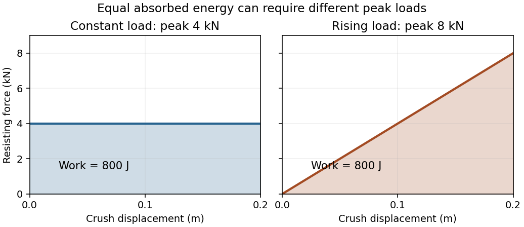
Original ideal crush-force curves: both absorb 800 J over 0.20 m, but their peak loads differ by a factor of two
. Details. A physical test must record the load history as well as the final crushed shape. One primary example used two vertical drop tests at with an energy-absorbing aircraft-seat prototype, a test dummy and acceleration measurements, using crash pulses informed by twelve light-aircraft crash tests. This tests a dynamic load path rather than merely a material's static strength.[ref]
Determination of crash test pulses and their application to aircraft seat analysis by E. Alfaro-Bou and others. NASA NTRS record 19810058363, author abstract; SAE paper 810611 (1981)
The carriage calculation above is an idealized energy budget, not a reconstruction of those tests.A force-displacement curve records how a measured force varies with a specified displacement during loading or unloading. The choice of displacement matters: it can describe specimen extension, motion of a machine crosshead or another reference. A curve can reveal resistance to motion, nonlinear response and differences between loading and unloading.
A concrete apparatus uses a moving crosshead, specimen fixtures and a load cell. The University of Illinois describes an Instron 4483 frame whose ball screws move the crosshead, whose load cell measures force, and whose encoder records crosshead position; an extensometer can separately measure specimen length change. The acquisition system converts those signals into engineering units and records them.[ref]
Load Frames at the Mechanical Testing Instructional Laboratory. Load Frames, apparatus and measurement-channel description
Those displacement channels need not agree. Crosshead motion can include mechanical compliance of the machine, grip seating and deformation elsewhere in the load train. A specimen extensometer therefore answers a different geometrical question from the crosshead encoder.[ref]
Extensometers in the Instron documentation. Passage on crosshead displacement, machine compliance, grip seating and load-train deflection
For a monotonic loading branch, the local slope is a tangent stiffness, while the ratio from a chosen zero point is a secant stiffness. These coincide for the linear model but can differ for a nonlinear curve. The force here is the applied loading force in the positive displacement direction; a spring's restoring force has the opposite sign.
The work supplied along this one-dimensional branch isFor an own linear example, and give final force and workThe nonlinear model , with , reaches the same final force but givesIts final secant stiffness is , while its tangent stiffness is . A final force and displacement therefore do not determine either the full curve or its work integral.
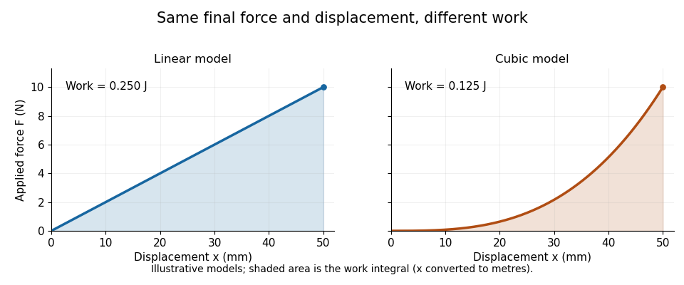
When loading and unloading follow different branches, a single-valued relation between force and displacement may be insufficient. Hysteresis records that path dependence; relating a cycle's work to dissipation also requires an energy balance and the relevant state assumptions. Report the measured displacement channel, sign convention and loading path before treating a curve as a material property independent of its apparatus.
Mechanical compliance describes how much displacement a mechanical system produces per applied force. For a one-dimensional linear response measured from an unloaded reference,where is the stiffness. Translational mechanical compliance has units . A larger value means a larger displacement under the same force. For a nonlinear force-displacement curve, the ratio and the local derivative need not agree; the latter is reciprocal to tangent stiffness where the inverse relation exists.
For a uniform bar in axial linear elasticity,where is its length, its cross-sectional area and its Young's modulus. Thus doubling the length doubles mechanical compliance, while doubling the area halves it, with material and other assumptions fixed.[ref]
Structural Stiffness Concept by TU Delft OpenCourseWare. Axial relation delta=PL/(EA) and discussion of material and geometrical influences
The same idea matters when measuring a specimen in a testing machine. The machine frame, load cell and grips also deform, so a crosshead's total movement can exceed the specimen's extension.[ref]
Universal Testing Machine Compliance by Instron. p1, What is it?
In an illustrative slowly loaded series model, each part carries the same force and their displacements add:Choose and . At , total movement is but specimen extension is . Treating the total as specimen extension would give an apparent stiffness of instead of .One apparatus-based correction loads a very stiff dummy specimen through the same load path, then subtracts its measured movement at matching forces. Its usefulness depends on reproducing the load path and making the dummy's own deformation sufficiently small.[ref]
Universal Testing Machine Compliance by Instron. pp2–3, dummy specimen and force-matched displacement subtraction
An extensometer instead measures extension directly over its chosen specimen length.A lead screw converts relative rotation into axial movement through a screw thread and matching nut. In a common arrangement the screw rotates while the nut is restrained from rotating and is guided along the screw axis. The constraint is essential: the useful output is their relative movement, rather than rotation of both parts together.[ref]
Selecting the Optimal Screw Technology by Tolomatic. Introduction, printed p4
Let be the screw lead, the axial advance per complete relative turn. With consistent directions and no backlash, an angular displacement produceswhere is the relative angular velocity. A screw with per revolution advances in a quarter-turn. This is a geometric prediction; free play, deformation and manufacturing deviations can change the measured motion.
The thread pitch is the axial spacing of adjacent threads. A screw with thread starts has , so a two-start screw with has . Lead and pitch agree for a single-start screw but need not agree otherwise.[ref]
Selecting the Optimal Screw Technology by Tolomatic. Screw Terminology, printed pp5–6: lead, pitch and single/double-start diagrams
An ideal slowly moving screw also illustrates the exchange of torque for axial force. Neglecting friction, changes in stored energy and other losses, equality of input and output work givesFor and , the required ideal torque is about . Real drive torque must also account for friction and other loads. Geometry alone does not determine whether an applied axial load can drive the mechanism backwards.
A lead screw is therefore both a motion-conversion mechanism and a load path. Its backlash affects reversals, while its mechanical compliance affects movement under changing force; these are distinct contributions to positioning error.
Backlash is free play in a mechanical coupling that can produce lost motion when the direction of drive reverses. In a lead screw, clearance between the screw thread and nut permits relative movement before the opposite contact surfaces carry the load.[ref]
Selecting the Optimal Screw Technology by Tolomatic. Screw Terminology, printed p5; Backlash, printed p18
Consider an ideal screw with screw lead per revolution and axial backlash . Suppose one thread flank initially carries the load and a small opposing force holds the carriage still while the screw reverses through the clearance. The angular movement required to take up the gap isDuring that interval, screw rotation need not produce carriage movement. A commanded reversal of corresponds geometrically to , but this simple gap model leaves only about of carriage travel after taking up the backlash.
The example assumes a particular contact state and holding force. If another force keeps the same thread flanks in contact, or moves the carriage across the gap, the observed reversal can differ. Thus backlash must be associated with a load condition, rather than inferred from every mismatch between commanded and measured position.
A useful measurement records screw angle and carriage position while approaching a chosen position from both directions. Direction-dependent results can reveal backlash even when repeated approaches from one direction agree. Separately changing the applied force helps distinguish free play from mechanical compliance: elastic deformation changes with force after contact is established, while clearance permits a gap before that load path engages. Both effects can contribute to a path-dependent relation and hysteresis.
Stiffness describes the resistance of a specified mechanical system to displacement under an applied force. For a linear one-dimensional response measured from an unloaded reference,the stiffness is constant and has units . A nonlinear force-displacement curve requires a more specific definition: secant stiffness compares a finite change from a chosen reference, while tangent stiffness is the local derivative .
Stiffness depends on geometry as well as material. For a straight, uniform bar under axial linear elasticity,where is Young's modulus, is cross-sectional area and is length.[ref]
Structural Stiffness Concept by TU Delft OpenCourseWare. Axial relation delta=PL/(EA), force-deflection slope and geometrical contributions
Unlike the structural stiffness, Young's modulus relates stress to strain and is expressed in units of pressure.For an original example, take , and . ThenA axial load gives . Doubling only the length halves the stiffness and doubles this extension. The material's Young's modulus has remained the same.
Series and parallel spring stiffness depends on how the components are connected. Two identical ideal springs of stiffness carrying the same force in series have total extension , so their combined stiffness is . In parallel, equal displacement gives total force and combined stiffness . These relationships assume the stated force and displacement constraints.
The reciprocal is mechanical compliance in the scalar linear case. For a response involving several coupled displacements and forces, a stiffness matrix records the additional relationships; one scalar cannot describe every loading direction.
A screw thread is a ridge following a helix around an external or internal surface. Cylindrical threads repeat around a cylinder; tapered forms can instead follow a conical spiral. The thread's shape and dimensions determine how it mates with another threaded component.[ref]
A simple geometric model represents one reference helix on a cylindrical thread bywhere is the chosen radius, is an angle measured in radians, and is the screw lead. Increasing by returns to the same angular position while increasing the axial coordinate by . This curve describes a reference path, rather than the full three-dimensional ridge profile.
A thread start is a distinct continuous helical ridge. With equally spaced starts and thread pitch , the advance of one start per turn is . The same axial spacing can therefore coexist with different advances per turn.[ref]
Selecting the Optimal Screw Technology by Tolomatic. Screw Terminology, printed pp5–6: lead, pitch and single/double-start diagrams
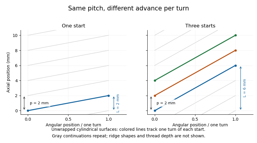
When a matching nut is guided against rotation, relative rotation can produce axial movement in a lead screw. Clearance can produce backlash, while deformation of loaded components contributes mechanical compliance. Thus ideal thread geometry predicts a motion ratio, while the actual load path also depends on contact and deformation.
An inerter is an ideal two-terminal mechanical element whose equal and opposite terminal forces are proportional to the relative acceleration of its terminals. With displacements , define the forces applied to the device asThe parameter is its mechanical inertance and has units of mass. Both terminals can move; if their accelerations are identical, this ideal constitutive law gives zero terminal force. Malcolm C. Smith introduced the element in a 2002 mechanical-network synthesis paper.[ref]
Synthesis of Mechanical Networks: The Inerter by Malcolm C. Smith. Abstract and pp1648–1651, two-terminal element and realizations
The power and stored-energy relation explains its role. Let . ThenAn ideal inerter stores and returns energy; this relation is not viscous dissipation. For an original force calculation, and relative acceleration give a 20-newton terminal-force magnitude.
A rotational realization also shows why inertance need not equal the assembly's translational mass. In an idealized rack and pinion driving a flywheel, suppose relative terminal speed produces angular speed . A flywheel with moment of inertia has energyso its ideal equivalent inertance is . Choosing and gives . This is a transmission-based example, not an assertion that the physical flywheel has a 200-kilogram mass.[ref]
Synthesis of Mechanical Networks: The Inerter by Malcolm C. Smith. Mechanical realizations and flywheel-based element
Friction, backlash, compliance and finite travel alter real-device behavior. An inerter can be combined with a spring or viscous damper, but their constitutive roles remain different: relative acceleration, displacement and velocity enter different element laws.
Structural dynamics studies the time-dependent motion of structures under applied forces and their response after a disturbance. Inertia, stiffness and damping jointly determine that motion. A common linear small-displacement model iswhere collects displacement coordinates, is the mass matrix, the damping matrix, the stiffness matrix and the applied-force vector. Boundary conditions and the chosen coordinates are part of the model; a static force balance omits the velocity and acceleration terms.
A scalar version makes the consequences quantitative. Choose , and . Its undamped natural frequency isFor a constant 100-newton force, static displacement is . For a sinusoidal force , the steady-state displacement amplitude of this linear forced harmonic oscillator is insteadThese are original model values, not measurements of a building. They show why the force amplitude alone does not determine displacement: forcing frequency and damping matter.
Real structures have multiple normal modes. A 2025 study of a viscous inerter damper uses a numerical 20-storey building example and shows that inertia and flexibility associated with discarded modes affect the reduced model's tuning. Matching one nominal mode while ignoring those contributions can therefore misrepresent the coupled device–structure behavior.[ref]
Tuning of a Viscous Inerter Damper: How to Achieve Resonant Damping Without a Damper Resonance by Jan Høgsberg. Abstract, modal interaction, discarded-mode corrections and numerical building example
Measured motion can test a chosen model, while its predictions remain limited by assumptions about linearity, boundary conditions and loading. A large predicted response is a reason to examine those assumptions, not proof that an actual structure will follow the linear response indefinitely.
A flywheel stores kinetic energy in a rotating body. For fixed-axis rotation with moment of inertia and angular velocity , its energy and axial angular momentum areAn applied torque changes the angular momentum; a drive can put energy into the flywheel, and a load can receive energy as it slows. Energy varies quadratically with speed, while angular momentum varies linearly.
For an original idealized calculation, take . Slowing from to releasesThe wheel still retains4000joules at the lower speed. Delivering the5000joule difference uniformly over10seconds would supply an average power of500watts before losses. This example distinguishes usable energy over a speed interval from the energy at the initial speed.
A NASA laboratory demonstration combined two flywheels to regulate electrical power while supplying a commanded torque. Its G2 and D1 units used magnetically levitated rotating wheels, were mounted on an air-bearing table, and operated between20000and60000revolutions per minute. A load cell measured table force so that output torque could be inferred. The apparatus connects energy exchange with the reaction torque exerted on the surrounding structure.[ref]
Flywheel Integrated Power and Attitude Control System Demonstrated by NASA Glenn Research Center. opening paragraphs and load-cell/table-torque measurement
A flywheel can also produce mechanical inertance through a rack and pinion. If relative terminal speed gives , the ideal stored energy is and the equivalent inertance is . Bearing losses, friction and material stresses constrain real devices; the ideal energy equation alone is not an operating-speed specification.
A rack and pinion is a meshing gear pair that converts between rotation and straight-line motion. The pinion is the circular gear and the rack has teeth along a straight path. The ideal motion is described using the gear pitch circle, rather than the outer tips of the teeth. Manufacturer diagrams compare rack travel over one full pinion revolution and show how tooth spacing affects that travel.[ref]
CP Racks and Pinions: KHK Technical Information. printed pp270–271, Features and Movement of one cycle diagrams
For a fixed pinion axis and a guided rack, let be the pitch-circle radius and choose consistent positive directions. With angular displacement in radians,where and are angular velocity and angular acceleration. For an original example, and a quarter-turn give . A rotation rate of2revolutions per second gives .
Ideal lossless work transfer also givesThus a1newton-metre torque at the same20millimetre pitch radius corresponds to50newtons of tangential rack force. This is a kinematic and energetic model; it omits tooth deformation and friction. Backlash makes reversal especially important: a small rotation can take up clearance before the rack moves. The manufacturer's catalogue explicitly describes backlash adjustment through mounting geometry.[ref]
CP Racks and Pinions: KHK Technical Information. printed p271, Features of Tapered Racks and Pinions
In a flywheel-based inerter, a rack and pinion makes relative terminal translation rotate the flywheel. The motion conversion then changes the apparent mechanical inertance without requiring the translating assembly to have that same physical mass.
A gear is a toothed mechanical element that transmits motion and torque through contact with another gear or a rack and pinion. The teeth maintain a prescribed relation between the motions: unlike a smooth friction drive, the ideal gear ratio is set by geometry and tooth counts. The gear pitch circle supplies an imaginary rolling geometry for describing that relation; it is not the circle through the tooth tips.[ref]
For two external gears on fixed parallel axes, let be their tooth counts and let signed angular velocities use the same orientation. Each tooth on one gear must pass a tooth space on the other, so counting tooth passages givesThus a 20-tooth input driving a 40-tooth output makes the output turn half as fast in the opposite direction. An input of revolutions per minute gives an output of revolutions per minute in magnitude. These signs describe an external pair; a rack and pinion instead converts rotation into translation.
The useful trade is between angular speed and torque. In an ideal steady transmission, conservation of energy equates input and output power, . The same 20-tooth/40-tooth pair therefore turns an input torque of into an output torque of while halving angular speed. This does not create energy: more torque accompanies less angular displacement per input revolution. Real gears dissipate energy through friction, and backlash permits a small lost motion on reversal; tooth strength and bearings, rather than the gear ratio alone, determine allowable load.
Mechanical network synthesis constructs an arrangement of mechanical elements to realize a specified relation between applied force and motion. In the linear two-terminal setting, a natural specification is the mechanical impedancewhere and are Laplace transforms of terminal force and relative velocity, with zero initial conditions. Choosing elements and their connections to obtain a desired is the synthesis problem; calculating for an already chosen arrangement is the corresponding analysis problem. Malcolm C. Smith's 2002 work introduced the inerter as a genuinely two-terminal inertial element, allowing a broader class of passive mechanical networks than a construction restricted to grounded masses.[ref]
Synthesis of Mechanical Networks: The Inerter by Malcolm C. Smith. Abstract and pp. 1648–1651: passive one-port synthesis, two-terminal inerter and mechanical realizations
A linear spring with stiffness , a dashpot with coefficient , and an inerter with mechanical inertance have respective mechanical impedancesFor elements attached between the same two moving terminals, the relative velocity is common and their forces add, so their mechanical impedances add. Consequently the targetcan be realized by a inerter, a dashpot and a spring sharing those terminals. The units of the resulting mechanical impedance are . At angular frequency , the sinusoidal mechanical impedance is : the spring and inerter contributions are equal and opposite imaginary terms. A sinusoidal relative velocity of amplitude therefore needs a terminal force amplitude of in this ideal example.
The apparent cancellation does not remove stored energy. With relative displacement and , the terminal power satisfiesThe inerter and spring exchange stored energy, while the dashpot dissipates it. This balance verifies that the example is a passive mechanical network for nonnegative . A practical inerter can use a rack and pinion to drive a flywheel; friction, backlash and finite travel limit the frequency and displacement range over which the synthesized response matches the ideal mechanical impedance. Thus synthesis gives a testable target for an apparatus, rather than a guarantee that a real mechanism has no parasitic effects.[ref]
Synthesis of Mechanical Networks: The Inerter by Malcolm C. Smith. pp. 1648–1651: ideal-element assumptions, inerter and mechanical implementations
A mechanical bearing supports relative motion while transmitting constraint forces between machine components. A shaft support can permit rotation while constraining translation, with the permitted motions depending on its construction and arrangement. A ball bearing uses rolling contacts; a journal bearing supports a shaft through a sliding or fluid-film interface. The support reaction is distinct from resistance to the permitted motion: an ideal support can transmit a large transverse force with zero resisting shaft torque.[ref]
Shafts and Bearings by SDP-SI. §4.0, “Bearing Loads”, shaft support reactions and gear-loading cases
For a simple ideal shaft supported at axial positions0 and , an upward load applied at requires reactionsWith , and , the downward support loads are120N and80N. These reactions exist even if the shaft rotates without an applied resisting torque. In a real mechanical bearing, an illustrative frictional resisting moment at angular speed dissipates ; force equilibrium alone does not determine that loss.
A locating bearing arrangement fixes the shaft's axial position relative to the housing, while a non-locating bearing support permits the required axial displacement, for example from thermal expansion. The manufacturer distinguishes this arrangement from adjusted and floating arrangements.[ref]
Rolling bearings by SKF. Section B.2, “Arrangements and their bearing types”, printed p.70, locating/non-locating supports
Radial support does not by itself establish which support carries axial thrust.Selection must therefore consider permitted motion, combined loads, alignment and operating conditions. An idler support reaction determines a shaft-level load; it does not directly give each rolling contact's Hertzian contact pressure or a service-life prediction. Those require the bearing's internal geometry and a suitable load/life model.
A rotating accelerometer is an accelerometer whose sensing axes rotate with a moving component, such as a gear shaft. It can measure motion close to its source, but its output combines the point's actual acceleration with a changing projection direction. Treating its channels as fixed laboratory axes can therefore change the interpretation of a gear vibration spectrum. A NASA transmission experiment mounted a microelectromechanical system sensor package on a pinion and compared it with stationary housing measurements.[ref]
For a rigid shaft rotating in a plane, let its center have inertial acceleration . An attached point at radius haswhere rotate with the shaft. The radial contribution is the rotating-accelerometer centripetal term. At constant and , its magnitude is even without vibration of the center. For the ideal specific force convention, the measured vector is projected onto each sensor axis, so gravitational acceleration can also produce a changing projection.
Suppose a laboratory acceleration projects onto a sensor direction rotating at . The product contains components at and :This measurement geometry can produce modulation sidebands without a damaged tooth. The NASA radial channel showed1854 and2060Hz around a1957Hz mesh frequency with103Hz rotation. Paired tangential channels also allowed different motion contributions to be separated by sums and differences.[ref]
Evaluation of MEMS-Based Wireless Accelerometer Sensors in Detecting Gear Tooth Faults in Helicopter Transmissions by David G. Lewicki and others. Printed p.21, equations(1)–(2); Figure20, printed p.23
Correct interpretation therefore specifies mounting radius, orientation, measurement calibration and rotation timing, as well as sensor bandwidth.Condition-based maintenance uses observations of a machine's condition to inform inspection, repair or replacement decisions. The chain runs from a physical measurement, through an interpreted condition indicator, to an action rule. A signal change alone is not that complete decision process. For a gearbox, useful observations can include a gear vibration spectrum, lubricant debris and direct inspection of gear surface pitting.
A motivating primary experiment monitored24 pinion/face-gear sets during endurance testing. Accelerometers and shaft-timing sensors supplied vibration records, while an in-line oil-debris sensor provided another physical channel. Inspection observations supplied evidence about actual damage. The study compared indicator responses and their detection/false-alarm tradeoffs, showing why an indicator needs validation against component condition.[ref]
Gear Fault Detection Effectiveness as Applied to Tooth Surface Pitting Fatigue Damage by David G. Lewicki and others. Printed pp.1–5, test facility, instrumentation, damage observations and detection analysis
For an illustrative decision process, compare an operating-state-matched baseline with repeated new measurements, investigate a persistent change, and select the response using evidence about the affected component. An alarm threshold that flags8 of10 damaged test cases and1 of90 healthy cases has observed detection fraction0.8 and false-alarm fraction about0.0111. These hypothetical counts describe one test dataset; choosing an action also depends on failure consequences, inspection cost and uncertainty. Receiver operating characteristic analysis helps expose the threshold tradeoff.
Detection and prediction answer different questions. Estimating remaining useful life additionally requires a model connecting future operation and degradation to a stated end condition. A detector that recognizes existing pits does not automatically supply that model. Changes in load, speed or sensor mounting can also change vibration, so a maintenance decision should state the measurement conditions and the interpretation being tested.
Pinned article: Introduction to the OurBigBook Project
Welcome to the OurBigBook Project! Our goal is to create the perfect publishing platform for STEM subjects, and get university-level students to write the best free STEM tutorials ever.
Everyone is welcome to create an account and play with the site: ourbigbook.com/go/register. We belive that students themselves can write amazing tutorials, but teachers are welcome too. You can write about anything you want, it doesn't have to be STEM or even educational. Silly test content is very welcome and you won't be penalized in any way. Just keep it legal!
Intro to OurBigBook
. Source. We have two killer features:
- topics: topics group articles by different users with the same title, e.g. here is the topic for the "Fundamental Theorem of Calculus" ourbigbook.com/go/topic/fundamental-theorem-of-calculusArticles of different users are sorted by upvote within each article page. This feature is a bit like:
- a Wikipedia where each user can have their own version of each article
- a Q&A website like Stack Overflow, where multiple people can give their views on a given topic, and the best ones are sorted by upvote. Except you don't need to wait for someone to ask first, and any topic goes, no matter how narrow or broad
This feature makes it possible for readers to find better explanations of any topic created by other writers. And it allows writers to create an explanation in a place that readers might actually find it.
Figure 1. Screenshot of the "Derivative" topic page. View it live at: ourbigbook.com/go/topic/derivativeVideo 2. OurBigBook Web topics demo. Source. - local editing: you can store all your personal knowledge base content locally in a plaintext markup format that can be edited locally and published either:This way you can be sure that even if OurBigBook.com were to go down one day (which we have no plans to do as it is quite cheap to host!), your content will still be perfectly readable as a static site.
- to OurBigBook.com to get awesome multi-user features like topics and likes
- as HTML files to a static website, which you can host yourself for free on many external providers like GitHub Pages, and remain in full control

Figure 2. You can publish local OurBigBook lightweight markup files to either OurBigBook.com or as a static website.
Figure 3. Visual Studio Code extension installation.
Figure 5. . You can also edit articles on the Web editor without installing anything locally. Video 3. Edit locally and publish demo. Source. This shows editing OurBigBook Markup and publishing it using the Visual Studio Code extension. 
- Infinitely deep tables of contents:




All our software is open source and hosted at: github.com/ourbigbook/ourbigbook
Further documentation can be found at: docs.ourbigbook.com
Feel free to reach our to us for any help or suggestions: docs.ourbigbook.com/#contact