
A steady state satisfies , henceThe sign is positive on the right after rearranging the supplied equation. A solution exists exactly when lies in the column space of , which above was found to be the zero-sum vector subspace. Equivalently, multiply by the left null space vector :This condition is necessary and sufficient for an algebraic steady state, since both the column space and that zero-sum vector subspace have dimension . It expresses global conservation of mass: in the closed box model, total tracer production must balance total tracer removal. With the paper's convention , a positive is a sink and a negative is a source. If the sum is nonzero, and the inventory changes linearly in time, preventing a steady state.
When the condition holds, all algebraic steady states form the affine solution space of a linear equation , for any particular solution . The initial inventory selects one member through . For a physically admissible solution, its four concentrations must additionally be nonnegative; the compatibility condition alone imposes no such inequalities.
The null space consists of concentration patterns on which transport produces no change. Here it is the familyEvery box has the same concentration. Ocean circulation may continue, but inflow and outflow of the chemical tracer balance in each box. With these are exactly the steady states; physically admissible members have . With nonzero , adding to any particular steady state leaves its transport balance unchanged, but a null space vector alone need not balance the sources and sinks.
To identify the tracer inventory, apply conserved inventory from a left null vector. Directly summing each column givesConsequently, for the supplied ordinary differential equations,For , is a conserved quantity. The connected box model equalizes concentrations, approaching the unique member of the null space with the initial inventory:The arithmetic mean is appropriate here because the supplied matrix has zero column sums. In a general box model the conserved quantity is , where is a positive left null space vector; for physical concentrations expressed per unit volume, these weights represent the box volumes up to a common factor. One must establish the weights from the equations, rather than infer equal volumes from a schematic drawing.
Nonnegative initial concentrations remain nonnegative under transport alone. Indeed is a nonnegative matrix, sohas nonnegative entries for : it is a positive matrix semigroup. Its column sums are one by . To see why equalization occurs, set for ; then andThe right side vanishes only for constant , which in the zero-sum vector subspace means . Its strict negative bound on the unit sphere in that vector subspace gives decay to zero. Thus the matrix exponential redistributes inventory without creating negative concentrations; arbitrary prescribed sinks can still exhaust the tracer if they are allowed to act indefinitely.
Regard as a linear map . By the rank-nullity theorem and matrix rank ,All three are vector subspaces of , with the row space identified with four-component row vectors in the usual way. The null space lies in the input vector space of concentrations; the column space lies in the output vector space of concentration-change rates. Both have four coordinates, although they play different physical roles.
In this particular matrix, the row sums and column sums both vanish. Put . Then and , and the two three-dimensional vector subspaces coincide:This equality follows here from both sum identities and the dimensions of a vector space; it does not make a symmetric matrix and is not true for every square matrix.
Since is an invertible matrix, is equivalent to . The last nontrivial row gives ; the second gives ; and the first gives , so . A basis of the null space is thereforeIts single basis vector has Euclidean norm , so the unit null space basis vector is .
The pivot elements of lie in columns . Take these columns from the original matrix to obtain a basis of its column space:The fourth column is minus the sum of these three columns, and the leading three-by-three matrix minor has nonzero determinant , confirming linear independence.
Elementary row operations preserve the row space. Thus the nonzero rows of give a basis of the row space of :These basis vectors need not have unit Euclidean norm or be orthogonal. Their Euclidean norms are , respectively; the three column basis vectors have Euclidean norms .
Apply Gaussian elimination to the supplied nonsymmetric matrix,The first pivot element is , with elimination multiplier . Perform , givingThe second pivot element is , with elimination multiplier . Perform , then use the third pivot element and elimination multiplier to perform . The LU factorization isHere is a unit lower triangular matrix, hence an invertible matrix, and is an upper triangular matrix. No row interchange is needed: all three pivot elements used in elimination are nonzero. The final diagonal entry is zero, with an entirely zero last row; there is no further division by it. The three nonzero rows of are linearly independent, so the matrix rank is and is a singular matrix. Direct matrix multiplication gives .
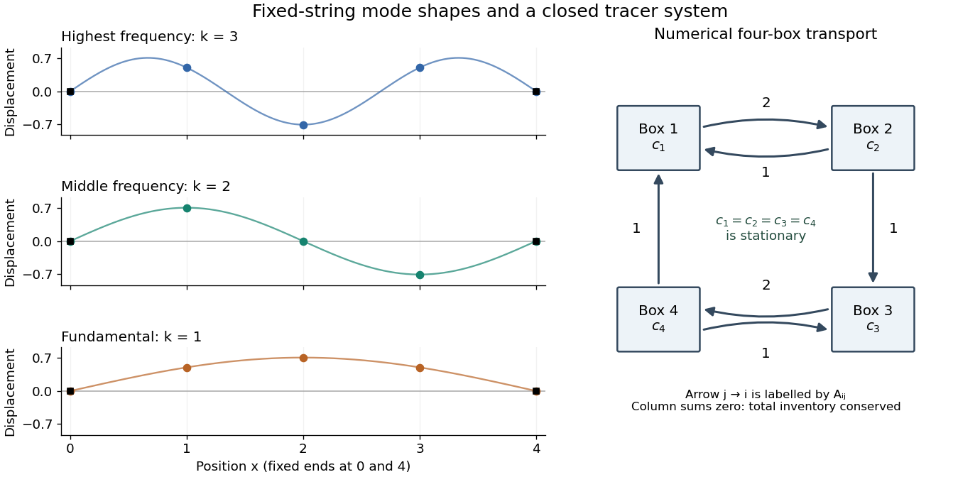
Each supplied eigenvector gives relative displacements at in a standing wave. Insert zero at to describe the whole sampled string. A real normal mode is : its shape stays fixed while its amplitude oscillates.
- is the highest-frequency resolved normal mode. Adjacent interior displacements alternate in sign: the middle point moves opposite to both outer interior points. Its interpolated shape has three lobes, corresponding to the third string normal mode.
- is the middle-frequency normal mode. The midpoint is a node of a standing wave, and the two sides move in opposite directions. It corresponds to the second string normal mode.
- is the lowest-frequency normal mode, corresponding to the fundamental frequency. All interior points move in the same direction, with greatest displacement at the centre; the only nodes of a standing wave are the endpoints in the smooth shape through these samples.
These semidiscrete fixed-string normal modes are samples of , with in the order listed. More precisely, their interior vectors are , which have unit Euclidean norm and form an orthonormal basis of . Their eigenvalues and angular frequencies obeyThus larger absolute value of a negative eigenvalue means faster oscillation, rather than faster decay. The numerical angular frequencies approximate the continuous fixed-string values ; the finite difference spatial approximation changes them. Only three independent interior normal modes exist on this grid, and any interior displacement or initial velocity vector can be expanded in this orthonormal basis.

For each row, a Gershgorin disc has centre and radius . Here and , so the Gershgorin circle theorem givesSince is a real symmetric matrix, its eigenvalues are real. Intersecting the union of these Gershgorin discs with the real axis yieldsThis bound permits zero but does not assert a zero eigenvalue. The fixed-end Dirichlet boundary conditions exclude it: for any nonzero real vector , extend by and calculateIndeed, equality would force every adjacent value to agree with the zero endpoint. Thus is a symmetric positive-definite matrix, is a negative-definite matrix, and the eigenvalues satisfy . The same argument works for any number of interior grid points, with prefactor in the sum. The fixed string has no zero-frequency rigid translation.
The interior grid is , with fixed-end displacements . HenceUse the monic characteristic polynomial convention , where is the identity matrix. Expansion of the determinant along the first row givesThe eigenvalues are the roots of a polynomial . With the alternative determinant convention , the characteristic polynomial is because the matrix has odd size; its roots of a polynomial are unchanged.
For a nonzero, time-independent vector , substitute . Taking two time derivatives givesCancel the nonzero exponential to obtain the eigenvalue problemThus an eigenvector specifies a normal mode shape and its negative eigenvalue specifies the square of its angular frequency, . Real displacements are obtained by taking the real part, or by combining the two temporal solutions as .
Put and suppose , so there are interior grid points , . Write . The fixed ends impose homogeneous Dirichlet boundary conditions,For a sufficiently smooth displacement field, the two Taylor series at fixed time givewhere all displayed derivatives on the right are evaluated at . Adding cancels the odd terms, leaving the second-order central differenceSubstitute this finite difference into the wave equation and retain continuous time. The resulting method of lines gives coupled second-order ordinary differential equations,In particular, the first and last equations are and for . With the interior displacement vector only,Equivalently, , , and all other entries vanish. This entrywise definition also covers small , including when . The matrix is a symmetric matrix and a tridiagonal matrix. The spatial approximation has error in Big O notation; time has not yet been discretized.
Excavate across the mapped fault scarp, approximately perpendicular to its strike, at a site where young sediments record and preserve deformation. On cleaned trench walls log bedding, soil horizons, shear zones, fissure fills, buried surfaces and colluvial wedges. Correlate the same marker beds across the fault before reconstructing individual displacements.
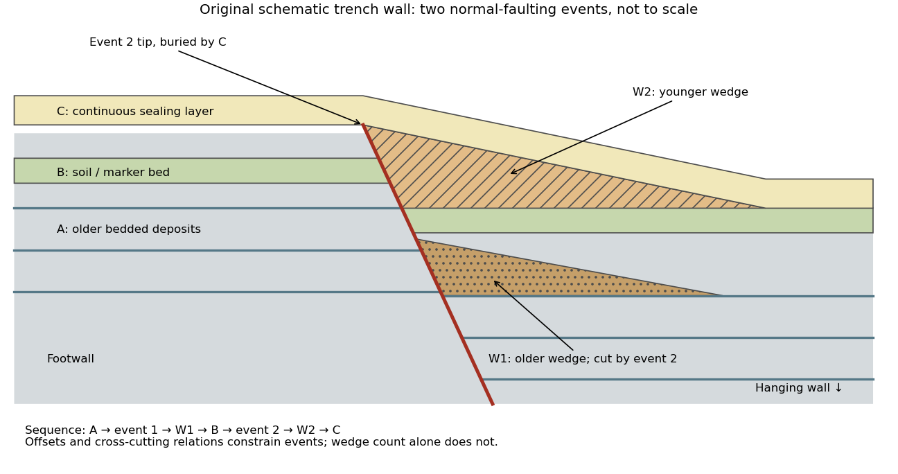

- A fault or fissure cuts older layers but terminates below an undeformed sealing deposit. The event occurred after deposition of the youngest demonstrably displaced material and before deposition of the oldest demonstrably sealing material.
- A fresh free face sheds coarse angular debris, often thickest against the scarp and thinning into the hanging wall; later finer slopewash can overlie it. A buried soil horizon between successive colluvial wedges can indicate a period of stability separating events. Fissures filled from above can preserve collapsed soil blocks or distinctive younger sediment.
- Older markers may have larger offsets than younger markers. A lower wedge or soil cut and displaced by a younger shear, then overlain by a new wedge and an intact seal, gives a cross-cutting basis for at least two events. Changes in displacement should be reconstructed across all fault strands.
- Rapid tilting, growth of accommodation space, abrupt changes in deposit thickness, and locally ponded beds can corroborate the structural evidence. Soil liquefaction structures or shaking-induced landslides may support a chronology, but do not alone prove surface rupture on the trenched fault.
In the drawing, A was faulted in event 1; W1 accumulated; B buried and stabilized that surface. Event 2 displaced A, W1 and B, after which W2 accumulated and C sealed the fault tip. Thus A records two events, B one and C none. This combination of offset and sealing relationships is stronger evidence than identifying two wedge-shaped units alone.
Bracket event ages with multiple samples just below and above the event horizons. Suitable short-lived organic material can be dated by radiocarbon dating; optically stimulated luminescence dating can constrain deposition of appropriate mineral grains. Reworked old charcoal, younger roots, incomplete bleaching, erosional gaps and time elapsed between rupture and wedge deposition must enter the age interpretation. For calendar dates, only when those deposits genuinely bracket the rupture; a radiocarbon age in years before present reverses the numerical ordering.[ref]
Introduction to paleoseismology by United States Geological Survey. “Finding Paleoearthquakes” explains disrupted layers followed by unbroken cover; “Determining the Age of a Paleoearthquake” explains dating deposits above and below the event horizon.
One earthquake can generate several debris pulses and wedges; repeated earthquakes may reuse one strand without leaving separable deposits. Erosion, bioturbation, nondeposition, lateral facies changes and upward-dying splays can hide events or mimic terminations. Confirm relationships on both trench walls and, when possible, in adjacent exposures. The result is a minimum supported event sequence with age intervals, not an assumption of perfectly periodic recurrence or one earthquake per wedge.
A surface-reaching normal fault earthquake commonly produces a down-facing step towards the hanging wall, accompanied by extension across the break. A fresh free face can expose bedrock, polish or striations, roots or offset soil. The actual rupture is usually irregular: fault slip changes along strike, separate strands overlap or step, and tension fissures, small grabens and secondary cracks distribute part of the extension.
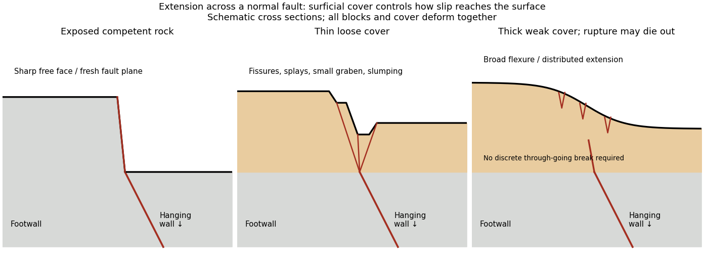
Original cross sections showing how surficial cover changes normal-fault surface rupture
. Competent exposed rock localizes a sharp free face; thin loose cover permits splays and a small graben; thick weak cover can accommodate a buried fault tip by broad flexure and distributed extension. Details.
Exposed competent rock or very thin cover: a relatively narrow, sharp break can closely follow the principal fault plane. A steep free face can be recognizable immediately, then weather and shed debris. The face need not be vertical or maintain the same height along strike.
Loose granular or poorly consolidated cover: the main shear can splay upwards through alluvium or regolith. Open fissures, step-like scarps, rotated blocks, synthetic and antithetic normal faults, and a small intervening graben can form across a wider zone. Collapse and raveling quickly build colluvium at the toe. A single rupture event can therefore create several parallel breaks; counting them does not count earthquakes.
Thick weak or cohesive cover: deeper fault slip can be transferred into distributed shear strain, tilted beds, broad warping or monoclines, with tension cracks above a propagating tip. A discrete break may be attenuated or absent if the fault remains blind. Cover thickness alone is not enough to predict the response: cohesion, grain size, layering, saturation, rupture displacement and fault depth also matter. Saturated loose sediment can additionally develop soil liquefaction, sand blows or lateral spreading; these are secondary shaking effects and do not independently locate the tectonic rupture.
The observed vertical step, crack aperture and total width of disturbed ground should be measured separately. Reconstruct the total displacement across all strands and account for the original ground slope. Landslides or gravitational spreading can imitate normal-fault scarps, so map connections to the main fault and displaced markers rather than assuming every open crack is primary tectonic slip.
The geomorphology of active normal faulting records a competition between accumulated tectonic displacement and the ability of erosion, transport and deposition to modify it. A hanging wall moves down relative to a footwall, producing a fault scarp, mountain-front relief, and accommodation space for a sedimentary basin. Repeated earthquakes can build a large front even though each individual surface break is much smaller.[ref]
Normal-fault geomorphic features by United States Geological Survey. The primary mapping report's table of geomorphic features lists scarps, faceted spurs, oversteepened mountain fronts and rejuvenated valley floors as common normal-slip indicators.
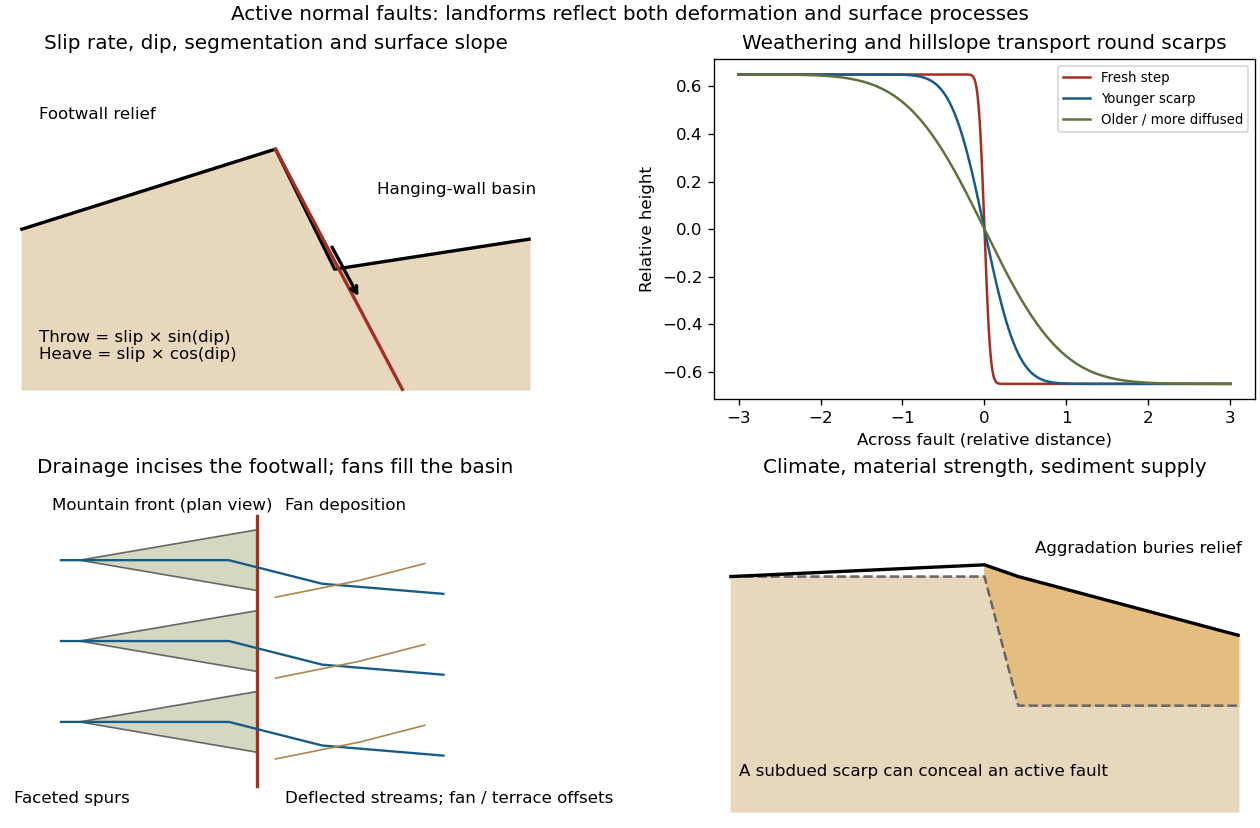
Original sketches of tectonic, erosional and depositional controls on normal-fault landforms
. The panels distinguish cumulative block displacement, progressive scarp rounding, drainage and faceted mountain fronts, and burial of a scarp by sediment. Geometries and relative scales are illustrative. Details.
The principal controls and their observable effects are:
- Displacement, rate and timing. Larger single-event fault slip creates a higher fresh scarp; repeated slip builds cumulative offsets of fans and river terraces. The interval since the latest rupture controls degradation. For pure dip-slip faulting on a plane dipping , vertical fault throw is and horizontal fault heave is . Scarp height on an inclined eroded surface need not equal either the slip or the original vertical throw.
- Geometry and structural history. Fault dip, strike, curvature, segmentation, splays and along-strike variations in fault slip control scarp orientation and continuity. Linked faults can create a stepped front; synthetic and antithetic faults can create a graben. Cumulative deformation includes broad footwall uplift and hanging-wall tilting as well as a sharp break.
- Lithology and cover. Strong exposed bedrock can preserve steep scarps and fresh fault surfaces. Weak fractured rock, thick regolith and loose alluvium weather and slump more rapidly, spread deformation, and produce debris at the scarp base. Differential erosion can make a lithological front without recent tectonic movement, so a straight cliff alone is not sufficient evidence of activity.
- Climate and surface transport. Rainfall, runoff, frost action, vegetation and slope processes control scarp rounding and colluvium production. Steep new faces collapse towards stable slopes; later hillslope transport rounds the crest and fills the toe. A simple scarp diffusion model broadens a step over a length proportional to , but only if a suitable transport law and comparable material and climate apply.
- Drainage and sediment supply. Footwall uplift can incise channels and produce river terraces, knickpoints and triangular faceted spurs. Hanging-wall subsidence can pond drainage, deflect streams and promote alluvial fans and basin filling. Rapid aggradation can bury an active scarp, while stream incision can remove or exaggerate local relief.
- Preservation and initial landscape. Pre-existing slopes, relief, surface ages, glacial modification and human disturbance determine where offsets can be recognized. A fan abandoned long before the latest earthquake can accumulate more offset than a younger nearby surface. Compare like-age markers across a fault, and distinguish a mountain front's long history from a single event.
Useful observations therefore include scarp profiles, repeated offsets of dated surfaces, drainage organization, and continuity along strike. A high rugged front is not by itself evidence of a high present fault slip rate; conversely, a muted or buried scarp need not mark an inactive fault.
The result predicts initial failure in a uniform material under the assumed principal-stress orientations. The actual Figure 3 is a present-day NW–SE cross section through a thick, heterogeneous Alpine stack, extending to about 50 km depth. It contains near-horizontal basal stretches, curved ramps, tightly bent contacts, and steep structures in the internal zones around Viso and the Dora Maira complex. It does not show a single undeformed conjugate pair newly formed in horizontal uniform rock.
Several processes explain the departures:
- Mechanical layering and inherited weaknesses. Faults can follow weak bedding, old fault planes, or contacts with lower friction or cohesion than the surrounding rock. These can form shallow décollements linked by steeper ramps. Figure 2 explicitly distinguishes the near-surface red “geophysical bedrock” boundary at a few hundred metres from the much deeper crystalline basement beneath the Jurassic, Triassic and Permian cover. An age label or a seismic contrast alone does not establish a friction coefficient; clay-rich or evaporite detachments are possibilities to test, not lithologies proved by that drawing.
- Rotation after formation. Continuing tectonic shortening, folding, stacking and fault slip can rotate an initially optimal fault plane to steeper or shallower present-day fault dips. A steep older structure may be inherited from an earlier deformation episode rather than created at its present orientation.
- Curved faults and local stresses. Faults bend through a layered crust; local principal stress axes rotate near topography, ramps and interacting faults. The optimum angle is measured relative to the local , not necessarily to the regional horizontal direction everywhere.
- Changing strength and deformation mechanism. Spatial changes in pore fluid pressure, coefficient of friction, cohesion and temperature alter which surfaces reactivate. At depth, ductile deformation can replace frictional brittle failure, so the same new-fracture construction need not apply throughout the section.
Finally, a section shows apparent dip unless it is perpendicular to fault strike. For an ideal plane, , where is the angle between the section direction and fault strike. Obliquity can make a plane look shallower, but cannot on its own explain an apparent dip steeper than its true dip. Do not infer that each black curve is a currently active brittle earthquake fault.
Assume an initially unfractured homogeneous isotropic material described by a linear Mohr-Coulomb failure criterion, with the given coefficient of friction representing the relevant internal friction angle. Use spatially uniform pore fluid pressure, effective stresses , and compression-positive signs. ThenThe Mohr circle in the plane has centre and radius . At first failure it is tangent to the failure envelope. The radius to the positive-shear tangent point is perpendicular to the line of slope , hence makes angle with the positive normal-stress axis.
If is the angle between the fault normal and , the stress transformation isThus , , and the angle of the fault itself to horizontal isThe two conjugate thrust faults therefore strike approximately east–west and dip about north and south. This is the fault dip, not the fault-normal angle. Both sediments and basement have the same optimum orientation under these assumptions because their stipulated friction slopes are equal; their cohesion and absolute failure stresses could still differ.
The first two panels in solution give the labeled construction. Constant cohesion shifts the straight failure envelope without changing its slope, and uniform pore fluid pressure translates the Mohr circle in normal-stress coordinates; neither changes this tangency angle. In the illustrative cohesionless case, , giving . Pre-existing weaknesses, a nonuniform stress field, anisotropic strength, or a nonlinear failure envelope invalidate the simple optimum-orientation prediction.[ref]
Stress and strength lecture notes by MIT OpenCourseWare. Lecture 10 develops the traction, pore-pressure and Mohr-circle framework; the signs and angle definitions above specify the convention used here.
There are unlisted articles, also show them or only show them.