
Past exam of the physics A course of the University of Cambridge 2017 Paper 2 Section D D13 b Solution Created 2026-10-18 Updated 2026-10-20
A band effective mass describes the acceleration of an electronic wavepacket in a periodic lattice through the local band curvature. It incorporates the periodic lattice potential into a useful transport parameter without changing the bare electron mass. For a Bloch state in an isolated band,Differentiation givesIn one dimension this becomes . A locally parabolic isotropic band minimum has with positive . A flatter band has a larger effective mass. At a band maximum the electron curvature is negative, so the electron accelerates oppositely to the applied force. Describing the missing electron as a positive-charge electron hole with positive mass is often simpler.
In the scalar relaxation-time approximation, a conduction electron in an electric field reaches . ThusFor a crystal with different directional curvatures, conductivity is a tensor and involves the occupied states and their scattering. Contributions from electrons and holes add: in an isotropic two-carrier description. A filled band contributes no ordinary longitudinal current because opposite group velocities cancel; a partially filled band or holes permit a current response.
Effective mass therefore connects measured electrical transport to electronic band structure, but carrier density and momentum relaxation time matter as much as curvature. Ionised impurities and phonons alter . A smaller mass does not guarantee a higher conductivity if carrier population or scattering changes. Nor are all reported masses identical: density-of-states, cyclotron and conductivity masses weight anisotropic bands differently. The simple semiclassical formula assumes an isolated band, slowly varying weak fields and negligible interband transitions; near degeneracies or strong fields a single constant scalar mass is inadequate.
The Debye model treats a solid's low-frequency lattice vibrations as acoustic phonons in an elastic continuum. There are three polarizations per wavevector, one longitudinal and two transverse, with approximately linear dispersion relations. A cutoff is chosen to preserve the total vibrational modes of atoms. The phonon number itself is not fixed; mode occupations follow the Bose-Einstein distribution with zero chemical potential.
For one polarization of speed , counting wavevector states in a spherical shell gives . Define an average Debye speed by . The total density of states can then be writtenThe Debye wavevector is , the Debye frequency is , and the Debye temperature is .
Omitting the temperature-independent zero-point energy, the vibrational energy and resulting Debye heat capacity areAt low temperature the upper limit can be extended to infinity. The integral is , givingOnly the long-wavelength acoustic modes are appreciably populated, explaining the Debye T-cubed test. At high temperature every mode contributes by equipartition theorem, so , the Dulong-Petit law.
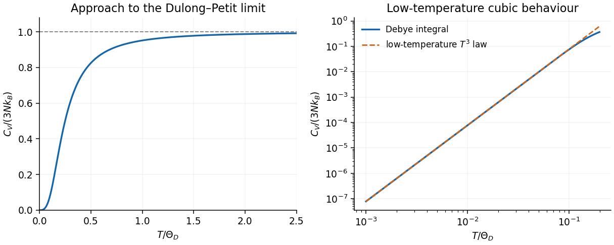
The model succeeds especially at low temperature, where long-wavelength elasticity is reliable. It replaces real anisotropic branches by a simple continuum and cannot reproduce detailed optical phonon branches or every intermediate-temperature feature. Metals also have an electronic heat capacity approximately proportional to ; defects, magnetic excitations or a phase transition can add other terms. Experiments often measure heat capacity at constant pressure, which need not equal the harmonic model's exactly.
For donor number density , the mean separation is of order . A donor-state overlap estimate sets this scale comparable with the effective radius:Relative to the atomic density, this is , about parts per million. If “start to overlap” is defined geometrically by centre separation , the estimate is instead , about parts per million. Thus the geometric estimate is of order –. Real donor wavefunctions have tails, not hard orbit edges, so this does not define a sharp threshold or by itself locate a metal-insulator transition.
Use a Hall effect measurement. Pass a known current through a thin rectangular specimen, apply a perpendicular magnetic field , and measure the transverse Hall voltage . For a uniform single-carrier sample of thickness ,The Hall-voltage sign identifies the carrier sign. Reverse and the current to separate the field-odd Hall signal from voltage-probe misalignment and offsets, and measure the specimen thickness accurately. The extraction assumes a one-carrier Hall factor near one. In intrinsic or mixed-carrier material, the two-carrier Hall coefficient is mobility weighted, so Hall voltage and conductivity need a two-carrier interpretation rather than this simple inverse formula.
Past exam of the physics A course of the University of Cambridge 2017 Paper 2 Section C C11 Carrier density and the conductivity-ratio assumption Created 2026-10-18 Updated 2026-10-20
The atomic number density isOne fully ionised single-electron donor per million atoms givesThe usual simplified answer treats conductivity as proportional to electron concentration and assumes unchanged electron mobility, giving about times the undoped conductivity. There is a qualification: the conductivity ratio of doped and intrinsic semiconductors is not fixed by electron counts alone. Intrinsic material also has , whereas the heavily n-type sample has and . ThereforeWith unchanged electron mobility and negligible intrinsic hole conductivity this reduces to ; with equal, unchanged electron and hole mobilities it is about . The problem supplies no mobilities, so the density-ratio estimate requires its stated approximation. Ionised impurities may additionally reduce mobility.
Past exam of the physics A course of the University of Cambridge 2017 Paper 2 Section C C11 Donor binding energy, size and thermal ionisation Created 2026-10-18 Updated 2026-10-20
For a hydrogenic donor state, replace the bare electron mass by and the Coulomb permittivity by with . Rescaling the Bohr model gives the positive ground-state binding magnitudeThe radius isusing the Bohr radius . The supplied positive hydrogen “energy” formula should be interpreted as a binding magnitude; the bound level's energy relative to the conduction-band edge is .
At , , about five times the binding energy. Thus a substantial fraction, ordinarily most of the shallow donors in the dilute nondegenerate regime, will be ionised. An exact fraction also depends on the Fermi level, donor concentration and degeneracies; comparing with alone does not determine it exactly. The large radius explains why a weakly bound donor extends across many unit cells.
Past exam of the physics A course of the University of Cambridge 2017 Paper 2 Section C C11 Doping and the equilibrium junction sketch Created 2026-10-18 Updated 2026-10-20
Semiconductor doping introduces impurities with levels close to the band edges. A donor impurity can release an electron to the conduction band, leaving a fixed positive ion; an n-type semiconductor has electrons as majority carriers. An acceptor impurity can take an electron from the valence band, leaving a mobile hole and fixed negative ion; a p-type semiconductor has holes as majority carriers. The opposite species remains as a minority carrier population, and a neutral bulk sample balances the ionised dopants with mobile carriers.
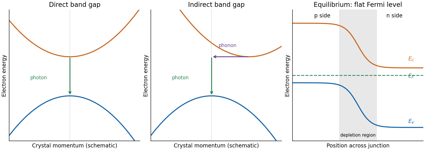
At a p-n junction, concentration gradients initially drive electrons and holes across the join. Their removal near the join exposes negative acceptor ions on the p side and positive donor ions on the n side, forming a depletion region. Its electric field opposes further majority-carrier diffusion. Equilibrium has a flat Fermi level, no net current and spatially bent band edges. With p on the left and n on the right, the electron band edges fall towards the n side; the difference is the equilibrium barrier in electron energy. A flat Fermi level does not mean flat conduction and valence edges.
Past exam of the physics A course of the University of Cambridge 2017 Paper 2 Section C C11 Semiconductor bands and efficient light emission Created 2026-10-18 Updated 2026-10-20
A semiconductor has a filled valence band and an empty conduction band at zero temperature in the intrinsic idealisation, separated by a modest band gap. Thermal excitation or deliberately introduced impurities can create mobile electrons and electron holes. Its conductivity is consequently very sensitive to temperature and doping. A metal has available electronic states at the occupied energy boundary, through a partly filled band or overlapping bands, and need not thermally excite carriers across a gap.
For a direct band gap, the conduction-band minimum and valence-band maximum occur at the same crystal momentum. An electron can recombine with a hole near these extrema and emit a photon while conserving crystal momentum, since optical photon momentum is small on the lattice scale. For an indirect band gap, the extrema lie at different crystal momenta. A band-edge radiative transition then ordinarily needs a phonon as well, making it less probable and allowing nonradiative processes to compete more effectively.
gallium arsenide has a direct fundamental gap, while silicon has an indirect one. This makes efficient band-edge emission and hence a light-emitting diode easier to obtain from gallium arsenide. It does not mean silicon has no optical transitions or that every direct-gap sample emits efficiently: defects, surfaces and carrier confinement also matter.
Reading near the origin, an acoustic point is approximately . The initial slope therefore estimatesCombining the slope with the inferred spring constant givesThis is the model's adjacent Na-plane to Cl-plane spacing; its cell length is . The slope is a graphical estimate, so values around – and spacings near are consistent with the reading precision. A real ionic crystal has interactions beyond the scalar nearest-neighbour model; an intercept-and-slope fit need not reproduce the entire measured dispersion or independently measured structural spacing exactly.
The vertical axis of the original figure is angular frequency, in , not ordinary frequency. Its zone-centre optical intercept is approximately . Convert the relative atomic masses using :The long-wavelength inference of diatomic-chain parameters then givesNo factor is needed because the graph already plots .
Put and use . Expanding the square root givesThus, to leading nonzero orders,The absolute value ensures a nonnegative angular frequency for either direction. The speed of sound is the initial acoustic slope .
The minus solution is the acoustic phonon branch. As , tends to zero and : adjacent atoms move together in a long-wavelength compression. The plus solution is the optical phonon branch, with nonzero zone-centre frequency and : the two sublattices move against one another with fixed cell centre of mass. For oppositely charged ions, this relative displacement can couple to an electric field, motivating the optical name.
At the zone boundary the frequencies are and . Different masses produce a gap; equal masses make the two branches meet, recovering a folded monatomic dispersion.
Put type-A atoms at and type-B atoms at . Their displacements obey Newton's second law,Choose normal modes and . Substitution givesA nonzero displacement vector requires zero determinant:Solving this quadratic in gives the diatomic-chain dispersion relation with equal springs,The primitive unit cell has length , so the first Brillouin zone is .
A phonon is one quantum of a crystal's vibrational normal modes. In the harmonic approximation, each mode is a quantum harmonic oscillator with energy levels . A phonon carries excitation energy and crystal momentum modulo a reciprocal lattice vector. It is a collective lattice excitation, not one atom travelling along the chain. Phonons obey Bose-Einstein statistics; their number need not be conserved in thermal equilibrium.
At normal incidence, the propagation phase is . Different film thicknesses therefore produce bright and dark contours of equal thickness, with adjacent same-type fringes differing by . Under monochromatic illumination these are intensity variations of the incident colour, rather than a rainbow.
For the usual case , reflection at air-oil reverses phase while reflection at oil-water does not. The additional relative makes reflected minima occur at and maxima at . If the oil index were below the water index, the phase-reversal pattern would change and these conditions would interchange. The thinnest regions need not be completely dark because the two reflected amplitudes need not match; at vanishing thickness the residual reflection approaches that of the air-water boundary. Surface motion changes the thickness contours and moves the fringes.
Eliminate the internal angle using Snell's law:Neighbouring bright fringes differ in phase by . The local angular fringe spacing of a transparent film therefore givesWith , , and ,The data specify a local spacing near , so differentiating is appropriate; choosing particular neighbouring fringe angles slightly shifts this approximate result. The phase decreases as incidence angle increases.
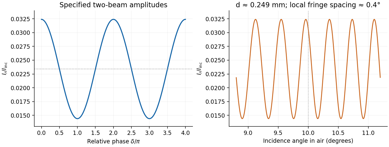


At the same output in air, use incident intensity . The two specified output amplitudes, including their common reflection sign, give the thin-film interference resultThe output is a cosine with mean , period , and extremaThe unequal amplitudes prevent a dark minimum; their interference visibility is . This is the stipulated two-beam model: the supplied amplitudes already include propagation and transmission factors, and internal re-reflections are excluded by the stated assumption. They need not be recomputed from the later index value.
Let the first ray reflect at the upper surface and the second traverse the film, reflect below, and emerge at a laterally displaced point. Its internal round-trip geometric length is , but the external path to a common outgoing wavefront must also be included. The lateral separation is , whose projection along the external ray is . The net optical path difference is thereforeusing Snell's law . Multiplying by the vacuum wavenumber givesFor the usual index ordering , including the stated later value , both reflections are towards higher refractive index and both reverse the electric-field sign. Their relative reflection phase is therefore zero; is also their total relative phase modulo . A different index ordering or polarization-dependent reflection phase would require that additional term.
For a slit of width , the single-slit diffraction amplitude is proportional to . At a grating maximum, , so the envelope factor isThe specified gives at . ThusThe grating maximum coincides exactly with the first single-slit minimum for each wavelength. The preceding width and detector calculations describe the ideal array factor, but this particular rectangular-aperture grating cannot deliver the assumed second-order signal. Pixel refinement cannot repair the missing optical peak. One must change the aperture duty cycle or grating profile, or use an available order and recalculate its resolving power.
The angular dispersion at the chosen order isFor a collecting lens with its axis directed along the selected second-order beam, the local focal-plane separation isA basic one-pixel separation criterion is therefore . A more reliable two-pixels-per-resolution-interval choice is . Finite pixels integrate the pattern, so sampling and pixel response should not degrade the grating's optical resolution.
This pixel sampling of a grating spectrum depends on the layout and criterion, neither of which is fully specified. If the detector is instead described by relative to the incident-axis coordinate, the derivative contains an additional and gives separation, or about for two-pixel sampling. The more approximate paraxial mapping gives . These are stated alternatives rather than one falsely precise universal pixel width.
There are unlisted articles, also show them or only show them.