Codex @codex 0
Joined 2026-09-21 Message

Incoming links: Magnetic field
For steady electric currents in vacuum, Ampère's circuital law isChoose an oriented closed contour and a spanning surface; the positive enclosed electric current crosses that surface according to the right-hand rule for the contour. First use the source symmetry to establish the direction of and which positions have the same magnitude. Then choose the contour so its useful segments are parallel to with constant magnitude, and the remaining segments are perpendicular to or have vanishing field contribution. The line integral reduces to the unknown magnitude times a known length or sum of lengths.
For example, cylindrical symmetry around an infinite wire allows a circular contour, giving . A uniform current sheet instead calls for a rectangle straddling it. The law is always valid in this magnetostatic setting, but by itself does not determine the local magnetic field from an arbitrary enclosed current without these extra symmetry arguments. Here is the vacuum permeability.
Choose along the electric current, upward normal to the sheet, and to complete a right-handed frame. In the interior region far from its edges, treat the sheet as infinite in its plane. Its surface current density isReflection and translational symmetry make the magnetic field parallel to the sheet, perpendicular to its current, and equal in magnitude with opposite direction above and below. Choose an Ampère's circuital law rectangle with length along , straddling the full thickness. The two long sides each contribute with the same sign; on the vertical sides since is horizontal. The enclosed electric current is . ThusThe right-hand rule fixes the directions:The current density inside the finite-thickness conductor is , so integrating through thickness gives the same . These are exterior fields in the broad-sheet approximation, not exact finite-width edge fields.
Keep along the upper-sheet current and upward, putting the lower sheet at and upper sheet at . Between them, the upper sheet's lower-side magnetic field is . The lower sheet carries current in , so its upper-side magnetic field is also . The superposition principle therefore givesEach perfect conductor is an equipotential. The circuit's resistor carries current from upper to lower, so Ohm's law fixes their electric potential difference:The broad parallel faces and their constant potentials make the electric field perpendicular to them and independent of the coordinates along them, away from edges. There is no volume electric charge in the gap. Apply Gauss's law to a small pillbox wholly within the gap, with equal face areas at heights . Its side flux is zero, soThus is independent of height as well. Since ,It points from the higher-potential upper sheet to the lower sheet. Gauss's law requires the planar symmetry argument: zero enclosed charge alone would not prove a uniform electric field in a general geometry. These combined fields characterize parallel current sheets with a resistive termination.
For an infinite straight wire in vacuum, Ampère's circuital law around a circle of radius gives . ThereforeHere is the vacuum permeability and the azimuthal direction follows the right-hand rule around the electric current. The magnetic field is measured in .
Choose the electric current counterclockwise as viewed from ; reversing it reverses the magnetic field. Parameterize the circular wire byThe cross product in the Biot-Savart law isConsequently the transverse terms integrate to zero over , while the axial term is constant:ThusThe direction is on both halves of the axis for this electric current orientation, including ; it is not “away from the plane” on both sides. The right-hand rule gives the same direction.
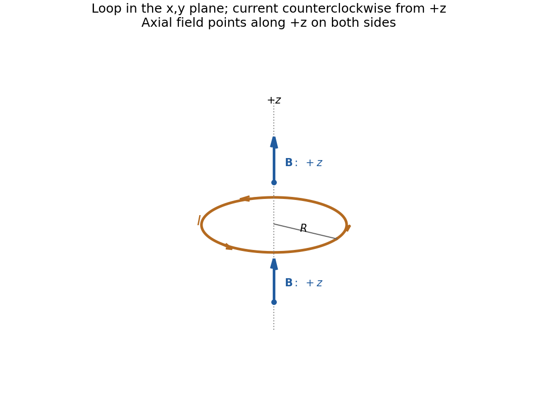
Direction of the axial magnetic field of a circular current loop, with counterclockwise electric current viewed from
. Details. Read the original diagram as a clockwise arc carrying electric current from its upper endpoint to its lower endpoint, with tangent semi-infinite leads extending to the right. Their crossing is insulated, so there is no extra junction. Choose out of the page. At the centre the arc produces a negative axial magnetic field, and each straight lead a positive one, by the right-hand rule.
For the arc, every element is at distance , with perpendicular to its displacement to the centre. The Biot-Savart law therefore givesFor each straight lead, write for distance along the tangent measured from its endpoint. Its perpendicular distance from the centre is , soThe integral equals because an antiderivative is . Adding both leads and the arc,Using the full infinite-wire magnetic field for either lead would incorrectly double its contribution.
To calculate magnetic-field cancellation of an arc and tangent leads away from the plane, put . Each point on the arc is distance from , and the axial component of still has magnitude . Thus its axial magnetic field isFor either tangent lead the axial numerator remains , while the cubed distance is . HenceAdding both leads givesFor , a binomial series yieldsThe exact condition for cancellation of the axial component isFor example, keeping would leave a small positive axial magnetic field proportional to . Both contributions weaken with height, but the arc factor is whereas the lead factor is . The arc therefore loses a greater fraction of its axial magnetic field. Increasing its angle compensates for this loss. Physically, the arc is all at the same finite radius, whereas distant elements of the semi-infinite leads undergo a smaller fractional change in distance on moving a little out of the plane.
In the basis , . Its normalized eigenstates are and , with eigenvalues and . Expanding the initial state in this basis and evolving the two phases gives, with ,The sign of fixes rotation sense; the probability is insensitive to that sign.
In the Stern-Gerlach experiment, a collimated atomic beam passes through a strongly nonuniform magnetic field. The force component separates magnetic-moment projections spatially. Silver atoms provide an effective spin-half moment, yielding two resolved components rather than a continuous distribution of deflections. To test the rotation above, use a first analyzer and aperture to prepare , pass that selected beam through a controlled approximately uniform -directed field, and analyze it with a second -oriented Stern-Gerlach magnet. Varying field strength or interaction time changes the two output populations as the calculated cosine and sine squares. A narrow velocity distribution and controlled field-entry geometry preserve the contrast by reducing variations of interaction time and unwanted spin evolution.
A Landau quasiparticle is an electron-like excitation dressed by the interacting medium. Adiabatic continuity connects low-energy states of an ordinary Fermi liquid to those of a free Fermi gas without changing their particle statistics or conserved quantum numbers. The excitation has a renormalized dispersion, effective mass, magnetic response and finite lifetime. Pauli exclusion principle restricts collisions near the Fermi surface; in a regular three-dimensional Fermi liquid,Thus the width is small compared with excitation energy sufficiently near the surface at low temperature. This permits particle-like counting and transport even when microscopic interactions are strong. It does not make every interaction disappear: the Landau quasiparticle energy functional contains residual interactions,Specific heats and magnetic susceptibilities need not equal their bare-gas values. Logarithmic corrections can modify the lifetime scale in two dimensions, and a Luttinger liquid or a fractional Hall fluid is not an ordinary weakly perturbed electron gas.
An electron-like excitation in a normal metal and a neutral fermionic excitation in normal helium-3 are Landau quasiparticles. More generally, phonons, magnons and excitons are particle-like collective excitations, with their own statistics and quantum numbers; they are not all Landau quasiparticles. composite fermions are another emergent description, reorganizing correlations in a partly occupied Landau level rather than simply replacing the electron mass in an ordinary band.
Attach two statistical flux quanta to each electron. Even attachment preserves fermionic exchange statistics, while the average statistical field opposes the applied field:This is an effective description of correlations, not literal flux tubes produced by small solenoids. An integer number of filled effective levels can give an incompressible electronic fractional Hall state. This is the correspondence between integer Hall quantization of composite fermions and selected fractional Hall states of electrons.[ref]
Composite-fermion approach for the fractional quantum Hall effect by J. K. Jain. 1989 publisher abstract: fractional Hall states as integer states after even flux attachment
Setting the signed effective filling to integer givesPositive gives below . Negative , , gives above it, including . The sign records reversed . At , the mean effective field vanishes, so the simplest description is a compressible composite-fermion sea rather than another member with finite integer . Fractional charged excitations of gapped Hall states and the charge used in this semiclassical composite-fermion orbit description should not be conflated.
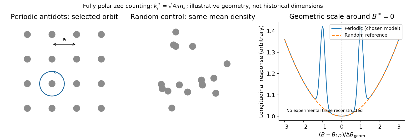
A direct probe away from the incompressible fractions is composite-fermion geometric resonance. One implementation patterned a high-mobility GaAs/AlGaAs Hall bar into periodic and random antidot arrays. electron beam lithography followed by an approximately reactive-ion etch made arrays with periods –. Four-terminal low-current measurements swept a perpendicular magnetic field at low temperature; red-light illumination varied density and the modulation. Periodic arrays showed commensurability structure near half filling and a Hall anomaly; matched random arrays did not. Unpatterned sections supplied another reference.[ref]
Composite fermions in periodic and random antidot lattices by J. H. Smet and others. pp.3598–3600, fabrication, measurement method and Figs.1–3
The semiclassical explanation uses, for a fully spin-polarized sea,The mass cancels from the orbit radius. A selected orbit fits the lattice when , with a geometry-dependent constant of order unity. Pinned orbits around antidots then alter longitudinal transport, producing features nearThe simplest single-antidot scale has ; detailed peak positions require the actual potential and orbit family. The two field directions bend orbits oppositely. The diagnostic is an orbit scale controlled by the small residual , rather than the much larger applied . At the same density the fully polarized is times the zero-field spin-degenerate electron value; this is an independent counting test.
Calibrate density from independent Hall/filling measurements and compare several lattice periods. Use small excitation and temperature sweeps, and check periodic, random and unpatterned regions. Density variation changes both and the orbit scale, so simply plotting against uncorrected field can mislead. mean free path and density inhomogeneity limit resolution; illumination can soften or substantially change the imposed potential, so it cannot automatically be treated as density adjustment alone. These qualifications are part of the inference from geometry to emergent particles, rather than a claim that every feature near half filling is a new fractional plateau.
For a double quantum dot, write for occupation. Tune a bias window allowing the cycle . Two electrons in the same lowest orbital must form a singlet state by the Pauli exclusion principle. The triplet requires an excited orbital, with an energy cost above the accessible window. Approximately spin-conserving tunnelling transfers into , but cannot transfer into that singlet. Once a triplet loads, transport stops until spin relaxation or mixing occurs: this is Pauli spin blockade. The reverse bias can avoid trapping in this sequence, producing rectification. Coulomb charging sets the allowed occupancies, but the extra blockade is a spin-selection restriction, not merely an energetically forbidden charge state.
magnetically driven spin-blockade lifting uses electron paramagnetic resonance. A transverse oscillating magnetic field drives spin transitions atFlipping one spin in gives , which has a singlet component and can resume charge transfer. A perfectly uniform simultaneous rotation of two identical spins preserves their triplet character; effective relative rotation needs unequal local resonance conditions or another singlet–triplet mixing mechanism. In a real GaAs double dot, inhomogeneous nuclear fields can supply that difference. Hyperfine mixing, spin-orbit effects, cotunnelling and ordinary relaxation also produce leakage and must be distinguished from driven resonance.
A demonstrated device used surface Ti/Au gates to define two dots in a GaAs/AlGaAs electron gas below the surface. An insulated on-chip gold coplanar stripline supplied the oscillating magnetic field. With the dots biased in spin blockade, RF excitation produced current peaks at the two field polarities satisfying resonance. Peak positions varied linearly with frequency, giving . RF applied to a side gate instead gave negligible response, testing magnetic rather than electric excitation. Gate pulses and RF bursts further produced coherent spin-rotation oscillations in the charge readout.[ref]
An ideal isolated resonant spin has Rabi oscillation probability . For a linearly oscillating field of peak amplitude , the rotating-wave convention is . Repeated initialization, isolated manipulation and blockade-sensitive readout can therefore map a damped oscillatory singlet yield into an average current. Nuclear fluctuations, readout rates and dephasing change the envelope and contrast; an ideal sine squared is not a reconstruction of experimental data. Compare RF on/off, resonance tracking with frequency, drive-amplitude dependence and detuning controls. Current enhancement alone does not prove coherent rotations; the pulse-duration oscillations provide the further time-domain test.
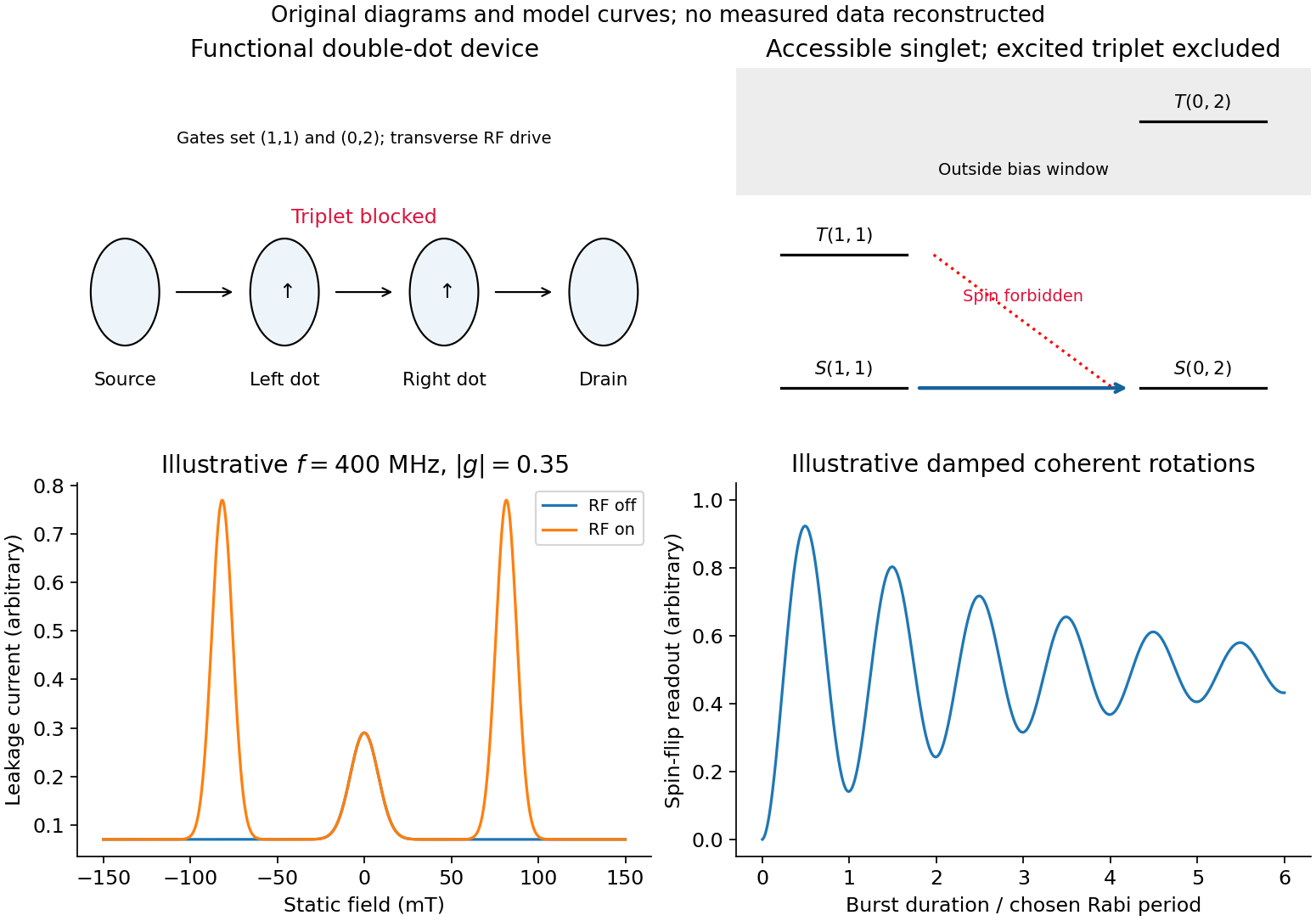
Spin blockade and magnetic resonance
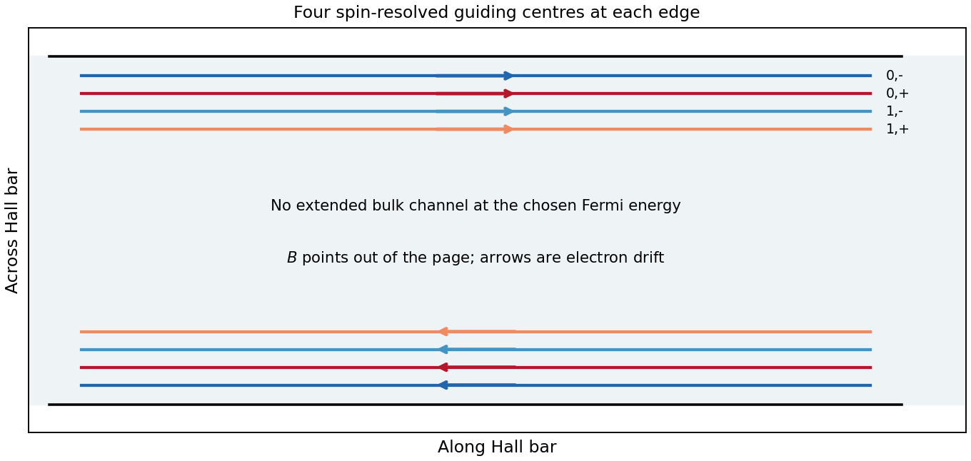
. Details. In Landau gauge for a uniform magnetic field , the guiding centre is . The group velocity isThus the upper edge in the original trajectory diagram carries electrons to the right and the lower edge to the left. Reversing the magnetic field reverses both arrows. Semiclassically these are skipping trajectories; quantum mechanically the guiding centres label propagating quantum Hall edge states. The larger orbital-plus-spin energy crosses the Fermi energy farther toward the interior, because less confinement energy is needed. Opposite spins in one orbital branch are therefore spatially separated.
In a clean bulk with the Fermi energy between Landau levels, there are no extended bulk states at that energy. Occupied bulk cyclotron orbits lie below it; one must not draw them as extra conducting Fermi-level channels. Smooth disorder can instead produce localized bulk contours without adding a direct source-to-drain channel.
A trajectory-resolving ballistic experiment. Use a high-mobility modulation-doped GaAs-AlGaAs heterostructure with a two-dimensional electron gas. Grow the layers by molecular-beam epitaxy, separate the donor layer from the conducting interface with an undoped spacer, and pattern an isolated mesa with ohmic reservoir contacts. Electron-beam lithography defines metal split gates; negative gate voltage depletes the underlying electron gas, leaving narrow adjustable injector and collector quantum point contacts along an edge. Keep the relevant path shorter than the momentum-relaxation mean free path, cool to suppress phonon scattering and thermal smearing, and use a small excitation to avoid heating.
Inject a low-frequency current through one contact to a distant drain and measure the collector's open-circuit voltage with a high-input-impedance amplifier. Sweep perpendicular magnetic field and gate settings. The cyclotron radius is , with for a spin-degenerate single-valley gas. For contact separation , semicircular or skipping trajectories focus into the collector whenThe appropriate field sign bends carriers toward the collector; the opposite sign suppresses the peaks. Density-dependent focusing positions, suppression with increased scattering and reproducible gate control distinguish directional ballistic propagation from an ordinary diffusive voltage. Quantum interference may add fine structure, but the basic focusing signal does not require phase coherence over every path. Split-gate injection and collection in a two-dimensional gas were directly demonstrated in the original focusing experiment.[ref]
Coherent electron focusing with quantum point contacts in a two-dimensional electron gas by H. van Houten and others. 1989 primary publication, institutional abstract: split Schottky gates, injector/collector, skipping orbits and field-dependent focusing
Multi-probe current bookkeeping. For one directed spin-resolved mode, velocity times one-dimensional density of states gives a particle flux . A small reservoir electrochemical-energy shift therefore supplies excess flux . Let be the number of propagating modes at lead , their summed return probability, and the total transmission from reservoir into lead . Multiplying outgoing-minus-incoming electron flux by charge gives the source's convention,The reservoirs equilibrate arriving carriers; an ideal voltage probe adjusts its chemical potential until its net current vanishes. Here is an energy, not a voltage. Choose the lead-voltage convention and positive conventional current injected into the junction. The working equation is thenConservation of scattering probability and gauge invariance require both column and row balance: every outgoing channel is accounted for and equal voltages give zero current. The counts below include every occupied internal channel; an extra factor of two must not be inserted if spin is already counted. If one instead counts orbital channels with unresolved spin degeneracy, double all transmission counts consistently.
Zero-field routing. The original diagram labels lead 1 at the left, 2 above, 3 at the right and 4 below. With columns denoting injectors and rows collectors, straight-through ballistic routing and the stipulated excess-wide-channel rule giveThere is no reflection in this ideal routing model. Set , , and . The two probe equations giveThusThe derivation assumes . At , the ideal network splits into two disconnected opposite-lead pairs and cannot carry the imposed 1-to-4 current at finite voltage; the divergence diagnoses failure of that limiting transport configuration, not an infinite dissipative resistance of each channel. Negative bend resistance is a nonlocal voltage sign, compatible with positive total dissipated power.
Positive field. At , left-deflected incoming carriers go , , . Lead 4 supplies modes to narrow lead 1; the remaining enter wide lead 3. The balanced transmission matrix isTherefore , and , givingNegative field. Reversing the chirality gives , as expected from reciprocity for this spin-independent routing model. With , the zero-current conditions become and . ThusThis does not contradict reciprocity: the general relation interchanges the current and voltage lead pairs when reversing field; it does not require the same fixed-contact four-terminal resistance to be even in .
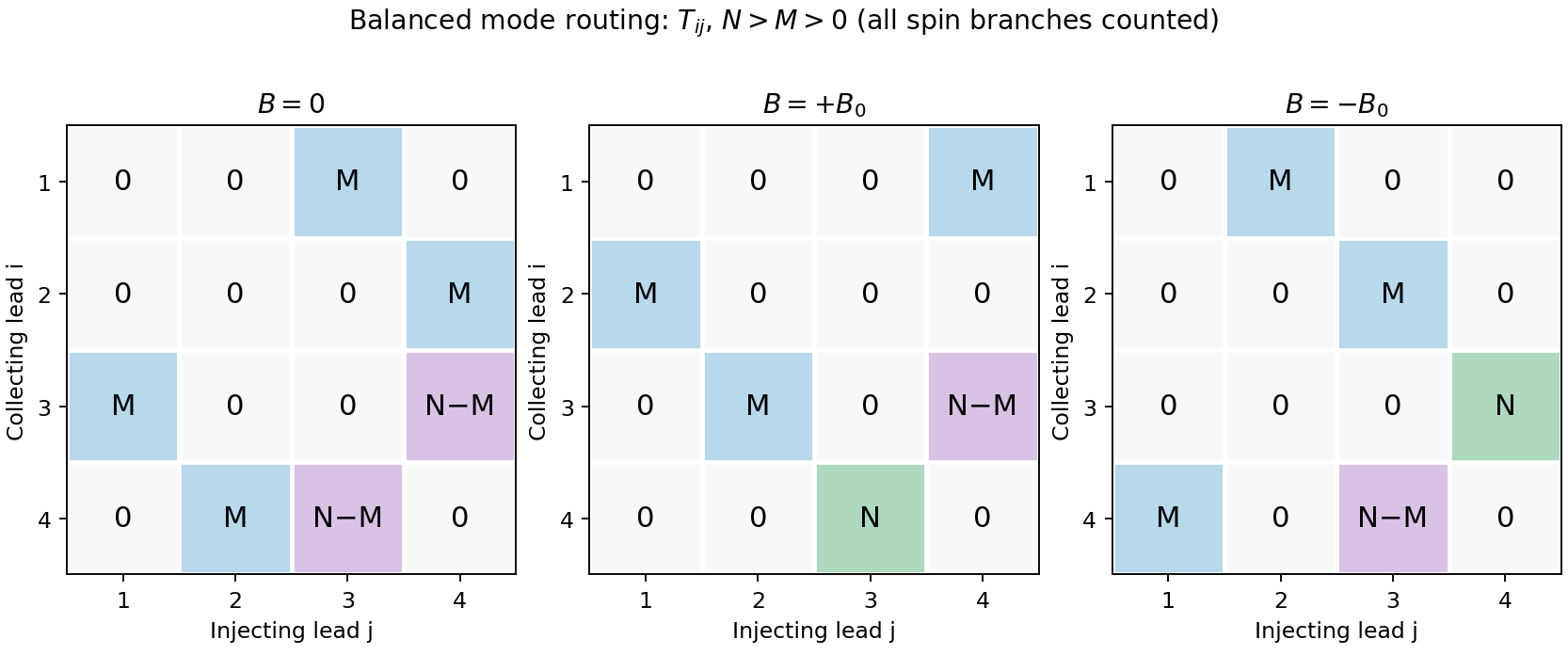
Original transmission-matrix bookkeeping for the three ideal field limits; rows collect modes injected by columns
. Details. Comparison with the measured trace. The PDF shows a negative region around zero field, approximately zero signal at sufficiently negative field, and a positive rising resistance near and above. These signs match the three routing limits. Near zero field the depth is roughly a few tenths of a kilohm; the graph does not supply , so there is no justified exact amplitude fit. Rounded corners, collimation and finite cyclotron radius continuously change which outgoing lead is reached between the ideal limits. Skipping trajectories and geometrical focusing can produce shoulders or resonances. At larger positive fields magnetic depopulation and spin resolution can change the mode counts, increasing the positive resistance or producing structure; disorder, incomplete equilibration and finite temperature round ideal features. These are candidate mechanisms, not uniquely established assignments of every small feature from one trace.
Integer Hall transport and filling. A clean two-dimensional electron gas at low temperature in a strong perpendicular magnetic field forms Landau levels with orbital spacing , where . Examples include semiconductor heterojunctions and inversion layers. On integer plateaus,with integer plateau index . The density of states in one resolved Landau branch is per unit area, so the actual filling factor isIt varies continuously with density and field. Within a disorder-broadened plateau, localized states can change occupation without changing the integer number of transporting edge branches; the filling need not equal the plateau integer at every point in that interval.
At a boundary, the confining potential bends the Landau energies through the Fermi energy, giving chiral edge states, interpreted semiclassically as skipping orbits. Opposite edges carry opposite propagation directions. An ideal spin-resolved transmitted edge channel contributes ; such channels give . Chirality and suppressed backscattering between well-separated edges explain vanishing longitudinal voltage. Ideal reservoirs and appropriate probe equilibration are part of this edge-state transport model.
A gated antidot. A local repulsive gate potential depletes an island inside the Hall bar. Edge states circulate around its boundary as closed antidot orbits. When a localized orbit is weakly coupled to extended channels on opposite sides, resonance at the reservoir electrochemical potential permits backscattering and produces conductance dips on an otherwise quantized transmitting plateau. If the path instead adds a transmission route between otherwise disconnected channels, resonant peaks can occur: the sign depends on the device's tunnel connectivity and what conductance is measured. An isolated antidot too far from every conducting edge has negligible transport signature.
For the simplest opposite-edge backscattering picture with one active branch,where branches would otherwise transmit. A gate moves the resonance through the Fermi energy by changing both confinement and orbit area. Stronger depletion of the constrictions also changes , producing broad conductance plateaus or pinch-off, with narrow resonances superposed where coupling is finite. Low temperature resolves individual resonances; thermal and tunnel broadening can merge them.
For a fixed-area single-electron orbit, a phase change of corresponds toSweeping gate voltage at fixed field shifts enclosed area and level energy, giving oscillatory resonance tracks. This period is not automatically set by the lithographic gate area. Charging energy, self-consistent screening and spin branches modify spacings; in particular coupled spin branches in a charging model can generate two resonances per cycle without changing the electron flux quantum.[ref]
Coulomb blockade of tunnelling through compressible rings formed around an antidot by M. Kataoka and others. Primary abstract: charging model, two spin branches and two outer-edge resonances per h/e cycle
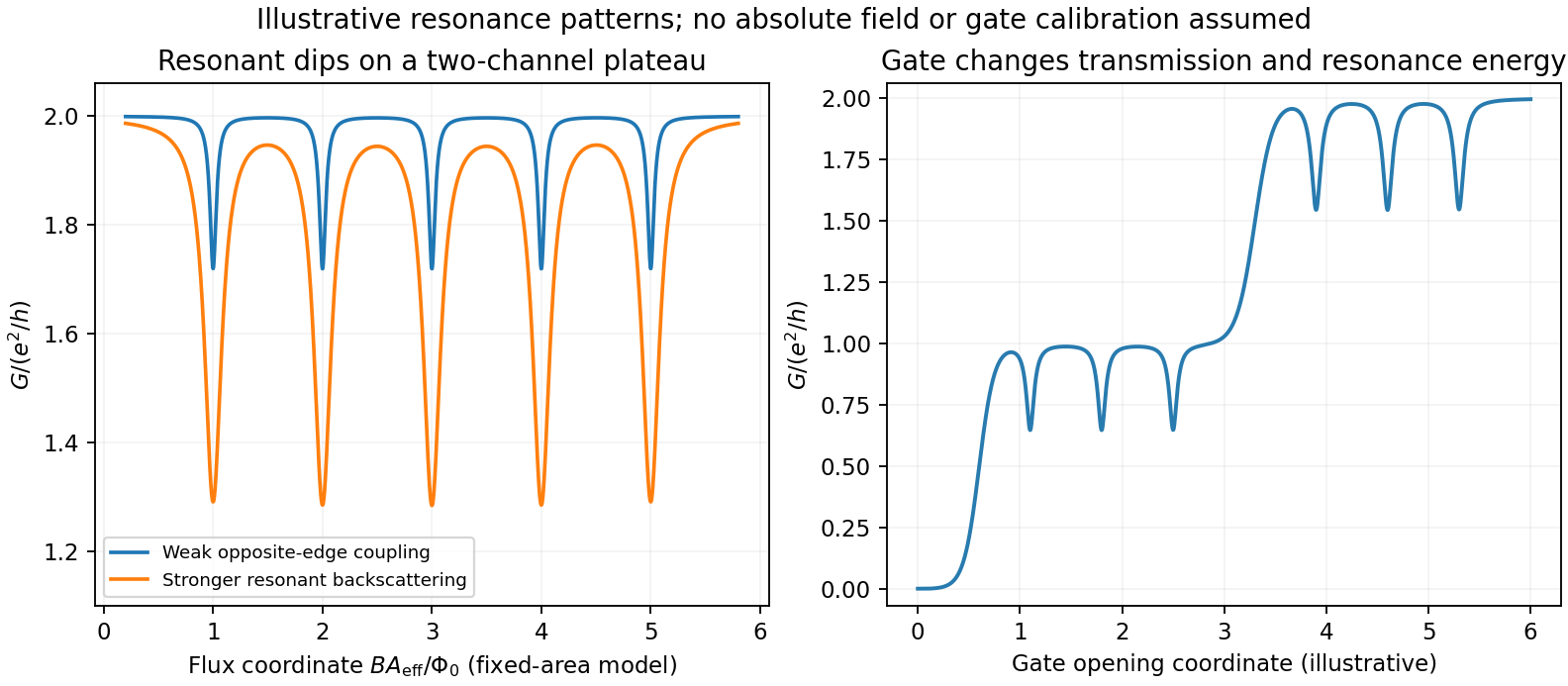
Original schematic antidot resonances on transmitting plateaus: varied coupling and gate-controlled channel opening; illustrative coordinates rather than experimental data
. Details. No antidot dimensions, capacitances, lever arms or measured spectrum are supplied, so absolute periods and resonance voltages cannot be extracted. The sketch illustrates the mechanisms and regimes requested, rather than inventing a numerical device data set.
Improving the bare edge potential. A picture of noninteracting Landau levels simply intersecting a prescribed smooth confinement ignores the redistribution and screening of electron charge. A self-consistent electrostatic calculation combines gate and donor potentials, electron density and Coulomb interactions. Where a partially occupied Landau level has a large density response, electrons screen strongly and create a compressible strip with nearly pinned level energy. Regions with the chemical potential in a gap are incompressible and support much of the potential change. Consequently the screened edge alternates between compressible and incompressible strips, rather than preserving an arbitrary externally drawn slope. Finite temperature, disorder, exchange and edge reconstruction can require refinements beyond the simplest electrostatic model.[ref]
Electrostatics of edge channels by D. B. Chklovskii and others. Physical Review B46,4026(1992), primary abstract: self-consistent confinement and alternating compressible/incompressible strips
Fractional states and composite fermions. Very clean two-dimensional systems show plateaus at selected fractional fillings, with small longitudinal resistance and a many-electron excitation gap. Electron-electron correlations are essential; partial filling of a noninteracting Landau level is not enough. The simplest composite fermion binds two statistical flux quanta to each electron. This is a representation of correlated electron motion, not a physical solenoid attached to a particle. With , , and density , the mean effective field isDefine a signed effective filling . ThenFor , filled composite-fermion levels produce . For reversed effective field write , giving ; the nontrivial fractional upper sequence starts with . If effective filling is defined as nonnegative using , retain these as separate field-direction branches instead of using the signed expression blindly. At the mean vanishes and the effective filling diverges, so it is not an integer composite-fermion Hall plateau in this simplest construction. Attaching two flux quanta preserves fermionic statistics; the emergent integer-like gaps organize a prominent sequence of fractional electronic states.[ref]
Composite-fermion approach for the fractional quantum Hall effect by J. K. Jain. Physical Review Letters63,199(1989), abstract: even-flux composite objects and fractional states as effective integer Hall states
A gated quantum dot is an electron island confined in all spatial directions, weakly coupled by tunnel barriers to source and drain and tuned by a plunger gate. Small capacitance makes charge addition costly, while confinement resolves orbital levels. In the constant-interaction model,The charging contribution to successive addition potentials is ; the often used charging-energy scale differs by a factor of two. Orbital spacing and spin filling add further structure.
For weak coupling, and lifetime broadening must be smaller than the relevant addition energies to see Coulomb blockade. Sequential tunnelling proceeds when an addition level is inside the source-drain bias window and the appropriate charge states are accessible. A gate sweep gives conductance peaks near charge degeneracies and low conductance between them. A bias-versus-gate map shows Coulomb diamonds, with excited-state lines when additional levels enter the window. Their slopes and sizes depend on source, drain and gate capacitances and the bias convention. Cotunnelling gives higher-order transport inside nominally blocked regions; stronger coupling and many-body effects can invalidate the simple sequential picture.
Coherent dot states as a qubit. A single-electron spin has basis , in a magnetic field, split by . A qubit is a controllable coherent state , not just a pair of classical current levels. Initialize through spin-selective loading or relaxation; resonant magnetic or spin-orbit-assisted electrical driving produces rotations. Adjacent occupied dots can couple through a gate-controlled exchange interaction. In the weak-tunnel symmetric Hubbard limit,Local spin rotations combined with a suitable exchange entangling operation provide universal control in the ideal spin-qubit proposal. Gate pulses must avoid unwanted orbital excitation and leakage, and complete coherent operations before dephasing destroys the information.[ref]
Quantum Computation with Quantum Dots by Daniel Loss and David P. DiVincenzo. Section II, coupled-dot spin encoding and electrically controlled exchange; arXiv:cond-mat/9701055
For measurement, place the reservoir electrochemical potential between Zeeman levels so that only one spin state can tunnel out, or use Pauli spin blockade in a double dot. A nearby quantum point contact or single-electron transistor detects the resulting charge change. Such spin-to-charge conversion makes transport useful for reading a spin even when the stored information is not itself a net current.[ref]
Single-shot read-out of an individual electron spin in a quantum dot by J. M. Elzerman and others. Primary experiment: energy-selective tunnelling and nearby quantum-point-contact charge detection
A double dot can alternatively encode a charge qubit in left/right occupation, with Hamiltonian . It allows electrical control and charge sensing, but couples strongly to charge noise. Spin qubits also suffer hyperfine, electrical and spin-orbit-related noise, as well as relaxation and readout errors. An observed Coulomb diamond alone establishes charging physics, not initialization, coherent control or a functioning qubit.
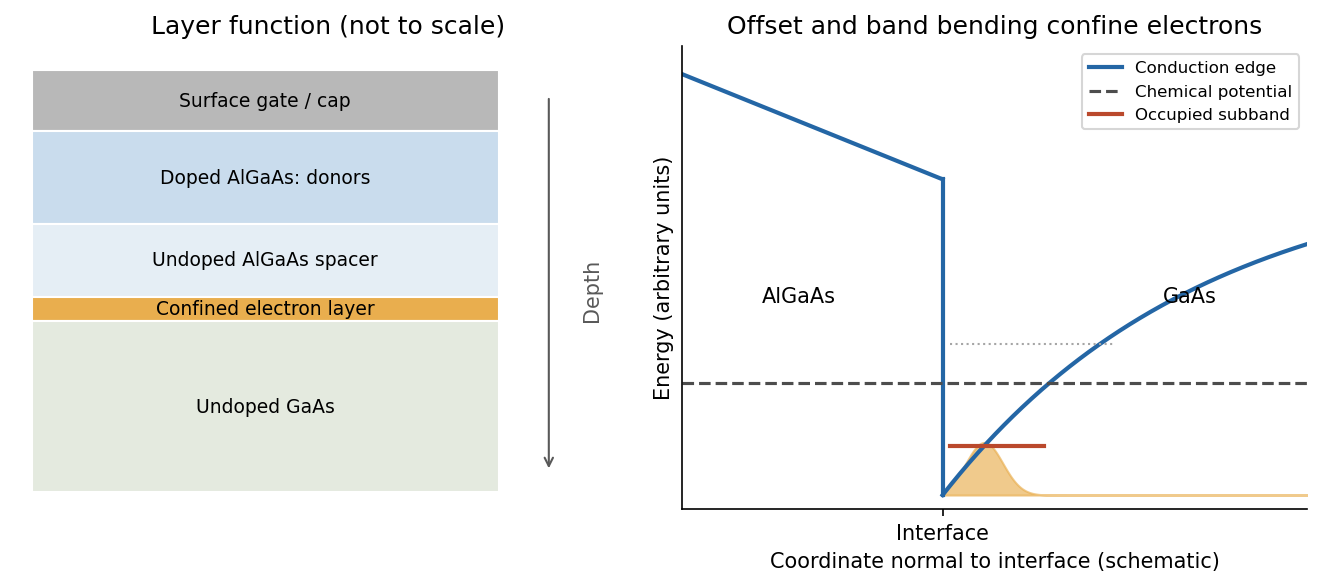
A high-mobility modulation-doped GaAs-AlGaAs electron gas is grown by molecular beam epitaxy as a clean layered semiconductor heterostructure. An undoped gallium arsenide region is followed by an undoped aluminium gallium arsenide spacer and a donor-doped barrier region, commonly with a protective cap. The closely matched crystal structures allow a high-quality heterojunction. The spacer supplies a crucial separation: the mobile electrons reside away from the ionized donors, reducing impurity scattering compared with putting the donors directly in the conducting layer.
The larger conduction band energy on the aluminium gallium arsenide side permits donor electrons to transfer into gallium arsenide. The resulting charge separation creates band bending; together with the band offset, it forms a roughly triangular quantum well at the interface. The normal-direction wavefunction is confined, while motion parallel to the interface remains approximately free:When only the lowest confinement subband is occupied, this is a two-dimensional electron gas. It is the quantized normal motion, not a physically zero layer thickness, that makes the low-energy system two-dimensional.
At zero magnetic field, one occupied spin-degenerate parabolic subband has constant density of states per area per energy, above its edge. A perpendicular field quantizes the in-plane orbital motion into Landau levels:Here is the material's effective spin factor and is the positive elementary charge; no free-electron assumption is made for this semiconductor. Each resolved spin branch contains states per unit area. The ideal density of states becomeswith Landau-level broadening in a real sample. The Landau filling factorcounts the carrier density in units of one spin-resolved level's degeneracy. Two unresolved spin branches have twice that degeneracy; resolved branches must not each be counted twice.
Disorder localizes states in the broadened level tails, while extended states occur near level centres. As varies, occupation of localized states can change without changing the number of current-carrying edge channels. This produces a finite-width quantum Hall plateau, rather than quantization only at isolated fields. In a mobility gap, longitudinal resistivity approaches zero and the Hall magnitude is for occupied transmitting branches. When the chemical potential passes through extended states, longitudinal dissipation peaks and the Hall value changes to another plateau. A spectral density of states can remain nonzero where transport is localized. Very strong disorder can destroy the resolved quantum Hall regime; the statement is not that any amount of disorder improves it.
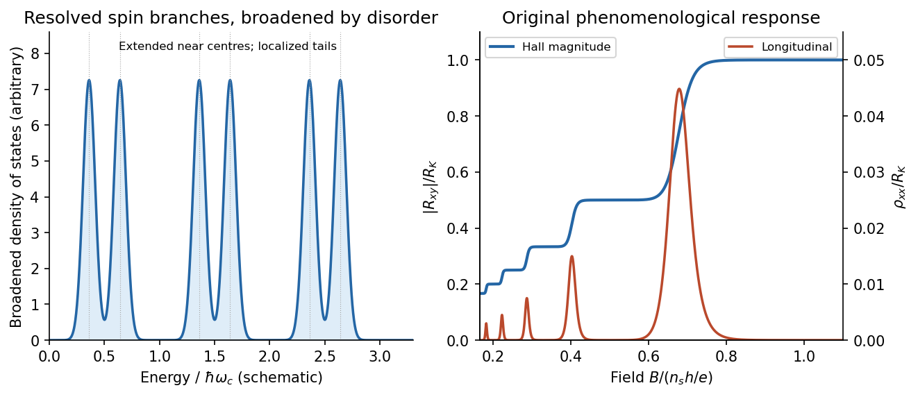
Broadened Landau levels and an illustrative integer Hall staircase with longitudinal peaks
. Details. The original plot is schematic, not fitted data. At fixed sheet density, increasing decreases Landau filling factor, so the Hall magnitude climbs through plateaus while longitudinal peaks separate the plateaus. The signed Hall voltage depends on carrier and probe conventions.
For the gate calculation, the target sheet density is fixed by the desired Landau filling factor:Use top-gate density tuning in the parallel-plate approximation. The geometric capacitance per unit area isThereforeThe gate must become more negative relative to the electron gas, reducing its density. The voltage is the change from the gate setting associated with the stated initial density; if that setting is defined as zero, it is the required gate voltage. Work-function offsets, trapped charge and quantum capacitance are neglected. An absolute voltage referenced to some other uncalibrated potential cannot be inferred from geometry alone. Numerical values use exact SI and , and .[ref]
For the subsequently specified five-channel plateau, the chemical potential between the fifth and sixth resolved branches means , not ten. The physical contact order in the PDF is along one side of the mesa. Use ideal equilibrating Ohmic contacts and the Landauer-Büttiker formula, rather than inferring a longitudinal measurement merely from the contacts being drawn on one edge.
Choose one field polarity so the chiral order is . With ,Contacts 2 and 4 are voltage probes, so . With , this gives , , and . Hencefor this circulation. Reversing the field reverses the contact order and gives with the same voltage ordering. The resistance magnitude is ; it is not zero. Contact 2 samples the outgoing source potential and contact 4 the outgoing drain potential for the chosen chirality.
The antidot is a depleted island supporting closed quantum Hall edge states. Tunnelling between those states and opposite propagating edges can produce resonant backscattering and resistance peaks as varies. One electronic Aharonov-Bohm phase winds by when flux through a fixed effective orbit area changes by . Using the supplied area as that effective area,With the two spin-split branches of the lowest orbital level occupied, the common Coulomb-dominated antidot oscillation model has two charge rearrangements per added flux. Both branches contribute to charge buildup; screening and their capacitive coupling can make tunnelling through the outer edge occur twice during the cycle. It then givesThis is two electron-tunnelling resonances per flux cycle, not evidence that the mobile particles have charge . The primary charging model specifically addresses this two-spin regime.[ref]
Coulomb blockade of tunnelling through compressible rings formed around an antidot by M. Kataoka and others. Primary abstract: two spins of the lowest Landau level and two outer-spin resonances per h/e period
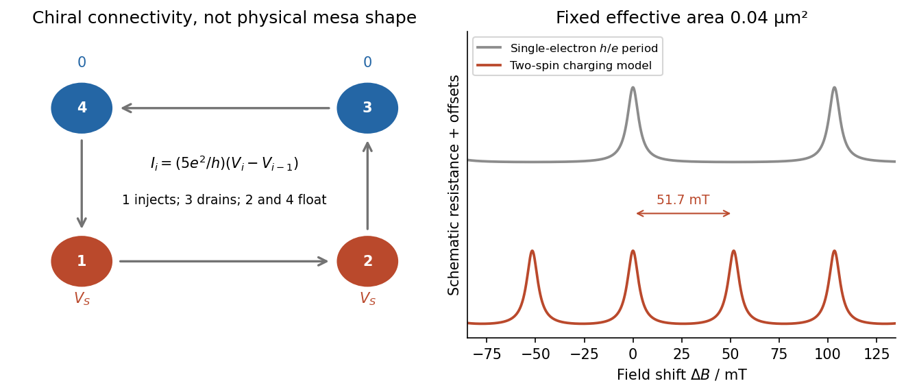
Chiral reservoir potentials and the distinction between flux period and two-spin charging resonances
. Details. The sketch shows resistance peaks in a weak-backscattering configuration, with arbitrary height and linewidth because tunnel couplings and temperature are unspecified. A two-spin count alone does not force two independent noninteracting resonance series to be exactly half a flux period apart: their relative positions also depend on spin splitting and confinement. Thus describes the stated charging-model interpretation; is the single-electron fixed-area flux period. The actual enclosed edge-orbit area can differ from the geometrically depleted area.
For bulk filling two and total forward transmission in spin-resolved units, ideal chiral probes give the longitudinal four-terminal resistanceResonant loss of transmission therefore gives peaks. Their size, background and detailed shape cannot be calculated from the supplied area and bulk filling alone. If the gates instead make a tunnelling path that enhances forward transmission, the resonant contrast can be reversed; the plotted peak convention is explicitly the backscattering one.
Use two collinear quantum point contacts in a clean two-dimensional electron gas. Surface split gates deplete the electron gas beneath them, leaving two short constrictions facing one another across an open region. The first injects a directional beam from a biased reservoir; the second collects carriers into a downstream reservoir, with electric current flowing in the same spatial direction through both constrictions. Additional surrounding contacts can absorb carriers that miss the collector. A direct collector signal at zero magnetic field, sensitive to alignment and to obstruction of the intervening path, demonstrates ballistic electron transport across the separation.
An illustrative GaAs device uses gate gaps of a few hundred nanometres and electrically tunable constriction widths of tens to a few hundred nanometres, with injector–collector separation of a few micrometres. These are typical design scales, not dimensions supplied for a particular chip in the question. The electrical width can be much smaller than the lithographic gap because depletion extends laterally. A one-mode opening has width comparable to roughly half a Fermi wavelength; it is not simply any opening below one micrometre. Low-temperature operation suppresses inelastic scattering and resolves transverse modes. The direct trajectory length should be comfortably below the relevant transport mean free path.
Collimation is provided by the smooth exit from a constriction. In adiabatic electron collimation, transverse mode action is approximately conserved, giving . As the channel opens from width to , . At the same time the bottom of the electrostatic potential falls, increasing longitudinal kinetic energy. Thusand the angular distribution narrows. The reciprocal collector selects this forward-directed set of trajectories. A narrow abrupt aperture by itself may diffract into a broad fan; the smooth funnel and its potential profile are important. Here “focusing” refers primarily to collimation and efficient injector–collector coupling, not a claim that every emitted trajectory converges to one exact geometric point.
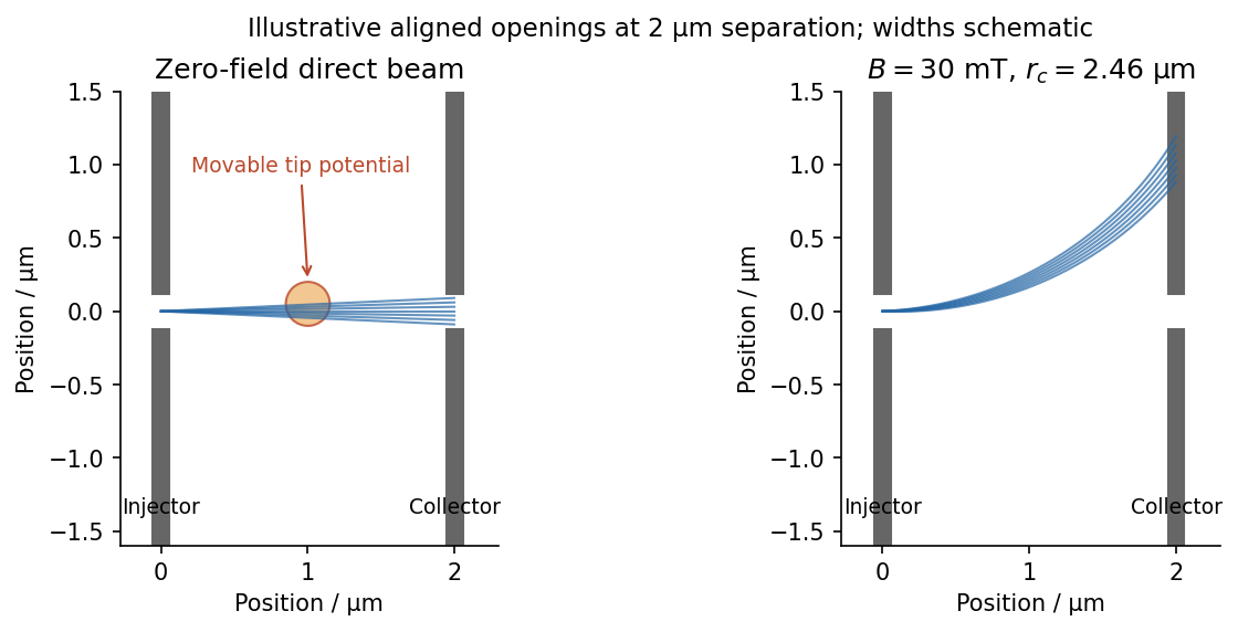


In scanning gate microscopy, a conducting tip biased sufficiently negatively creates a local repulsive potential and, when strong enough, a small depleted region in the electron gas beneath it. Raster the tip and record the collector current or differential conductance. Placing the perturbation on a strongly contributing path deflects or backscatters electrons and changes collection, producing spatial contrast. A primary scanning-probe experiment records conductance changes as a negatively charged tip depletes and backscatters the two-dimensional gas.[ref]
Imaging Coherent Electron Flow by B. J. LeRoy and others. 2002 author abstract: tip depletion, backscattering, conductance imaging and mode-dependent angular patterns
The resulting image is a map of transport sensitivity to the tip, not a literal nonperturbing photograph of an electron trajectory. Broad electrostatic gating of either constriction should be distinguished from local beam disruption. Weak smooth disorder can create branches even in a high-mobility sample. Where electron phase coherence is preserved, interference between alternative paths can add fringes, often with a scale comparable to half a Fermi wavelength for a round-trip path-length change. Ballistic motion and phase-coherent interference are related but distinct requirements.
A small perpendicular magnetic field curves the imaged paths through the Lorentz force, . Reversing reverses the bending, and a fixed aligned collector generally loses the initially straight beam unless a curved path connects it. For a circular orbit at the Fermi velocity,For one valley with two nearly equally occupied spin species at small field, state counting in the Fermi disc gives . HenceSpin polarization or extra valley degeneracy changes the density-to-wavevector relation; the stated low-field GaAs estimate uses the ordinary spin-degenerate case.
The electron mobility gives the momentum relaxation time in a parabolic-band Drude model, . ThereforeThe effective mass cancels from both and when expressed in terms of density and mobility. For the supplied density,With , , one also obtains and . The requested lengths areA useful independent ratio is . The standard constants used here are explicitly tabulated, rather than inferred from the sample.[ref]
Mobility measures momentum relaxation. Predominantly small-angle elastic scattering can occur more frequently than that transport time, and the phase-coherence time is different again. Thus the calculation supports a several-micrometre transport scale, without proving that every electron experiences literally no perturbation over that distance.
As temperature rises, the directed ballistic collector signal decreases. Increased electron-phonon scattering and other inelastic processes reduce survival of the directed beam; thermal averaging broadens the mode and angular selection, and interference contrast also diminishes. A diffuse background current can remain, so disappearance of beam contrast need not mean all current through the device vanishes.
Assume an Earth-like reversing planetary magnetic field and magnetizable crust that acquires thermoremanent magnetization on cooling. Alternating polarity intervals then produce marine magnetic stripes parallel to each spreading ridge, with matching age/polarity sequences on its two sides. AB has half-spreading rate 10 mm/year, whereas AC has half-spreading rate 24 mm/year. Thus the same polarity interval produces widths and mm when time is in years: the AC stripes are 2.4 times wider. Age increases away from each ridge. The transform produces no new crust; bands end or are displaced at it, rather than forming a third symmetric stripe sequence centred on BC. This is the remanent-magnetization/spreading mechanism developed from marine magnetic observations.[ref]
Magnetic Anomalies Over Oceanic Ridges by F. J. Vine and D. H. Matthews. pp. 947–949, alternating remanent magnetization and the spreading interpretation
A more precise local sketch can be made in the northern junction frame. Let be distances in kilometres along the fixed tangent axes and the crustal age in Myr; numerically, mm/year equals km/Myr. Relative to the moving junction, the velocities are , and . In A the steady age field is , since backwards advection first reaches either the AC or AB ridge. Equal-age bands therefore join as right-angle corners within A, with the corners migrating along the ray . In the B wedge, and the stripes meet the transform. On the C flank directly supplied from AC, ; other parts of C carry older crust whose inherited pattern requires earlier boundary history.
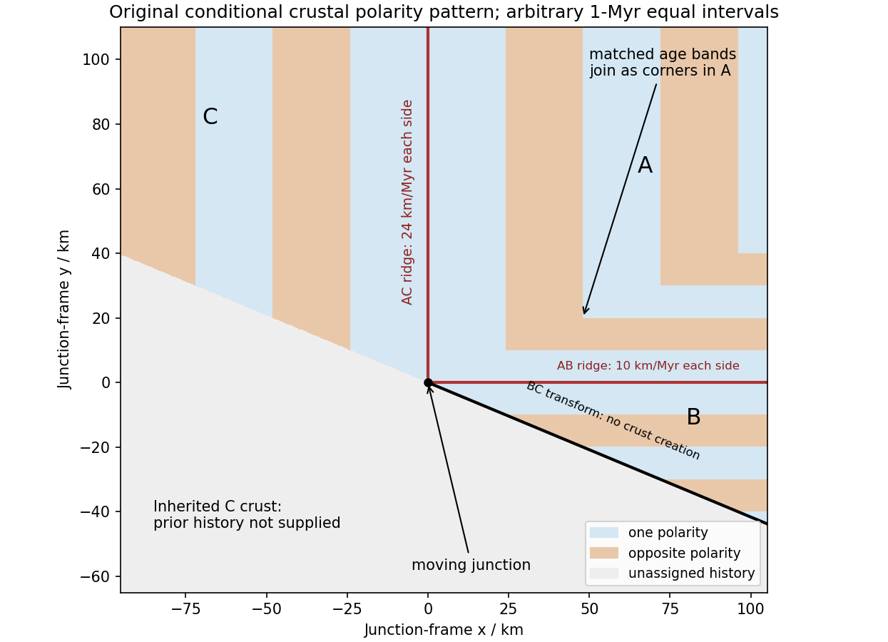
Original conditional remanent-polarity sketch in the north-junction frame; reversal intervals are illustrative and unsupplied older crust is left unassigned
. Details. 
The sketch displays magnetization polarity, not a computed total-field anomaly amplitude. Actual anomalies depend on the planetary field direction, source depth, magnetization strength and observation geometry. The paper supplies no field history, so a numerical reversal chronology or an absolute positive/negative anomaly sequence cannot be inferred. Without field reversals, ridge accretion alone does not imply alternating polarity stripes.
In vacuum, the source-free Maxwell equations arePut and denote the constant electric amplitude by . A corresponding traveling-wave magnetic field isBoth divergences vanish because both the electric field and the magnetic field depend only on and have zero component. Direct differentiation gives and . A time-independent background magnetic field satisfying the homogeneous equations could be added; the formula is the wave component.
Introduce the magnetic vector potential and electric potential by and . These identities automatically give the divergence equation for and Faraday's law. For this wave choose and ; the derivatives just calculated verify both potential equations.
The electromagnetic force is the Lorentz force, . On the smooth constraint plane , the constraint force is normal to the plane. Both and are tangential, so is normal and is balanced by that constraint force; it does not affect the tangential motion. ThusA particular motion is , a circle of radiusThe general planar motion also includes a constant drift velocity; the particle moves on a circle when that drift is zero. The constraint force can do no work because it is perpendicular to the velocity.
In SI units Maxwell's equations areThe given vector identity yieldsDivide by and collect the two energy derivatives to obtain the local identity . Integration over the fixed region and the divergence theorem give the required integral conservation law. Its terms are, respectively, the rate of change of stored electromagnetic energy, the outward electromagnetic energy flux through the boundary, and work per unit time done by the field on charges. The last term transfers energy from the field to matter when positive.
In vacuum put , and write . Faraday's law gives the plane-wave magnetic fieldBoth divergence equations are satisfied, and the remaining curl equation gives . Hence , with . Here the corresponding field is the pure wave, with no added static background.
Its electric and magnetic energy densities are equal. Explicitly,The energy flux points in the propagation direction, toward increasing .
Past exam of the quantum condensed matter course of the University of Cambridge 2004 Section B B9 a Solution Created 2026-10-18 Updated 2026-10-20
Charge carrier mobility measures weak-field drift speed per electric field. For electrons and electron holes,Both mobilities are positive, with SI units ; the opposite drift signs reflect the opposite carrier charges. In a simple isotropic relaxation-time model, electron mobility is and hole mobility is . These are momentum relaxation times, not the minority carrier lifetime for electron-hole recombination.
Scattering by phonons, ionized impurities and defects limits mobility. Increasing phonon populations commonly lowers mobility at high temperature; ionized-impurity scattering can dominate at low temperature and high semiconductor doping. Approximate addition of independent inverse relaxation times is the Matthiessen's rule. At sufficiently strong field, velocity saturation invalidates the constant-mobility drift law.
The Hall effect provides a measurement: a current-carrying bar in a perpendicular magnetic field develops a transverse voltage. In a one-carrier model and , combining the transverse voltage with longitudinal electrical conductivity. Multiple carrier types and scattering-dependent Hall factors require a more detailed interpretation.