
Magnetostrictive actuator Created 2026-10-18 Updated 2026-11-05
A magnetostrictive actuator uses magnetostriction to produce displacement or force. Its free motion and its blocked stress are different boundary conditions, as shown in free strain and blocked magnetostrictive stress.
Fluxgate magnetometer 2026-10-18
A fluxgate magnetometer uses a periodically driven magnetic core and pickup coils to measure a magnetic field.
Ferromagnetism 2026-10-18
Ferromagnetism is collective magnetic order with spontaneous magnetization below a Curie temperature. Interactions favor aligned magnetic moments; the Ising model represents a two-orientation version with positive coupling.
A magnetic domain can possess spontaneous magnetization even when other domains cancel its contribution to the whole specimen. Compare this spatial cancellation between domains with antiferromagnetism, where opposing magnetic sublattices compensate within the ordered structure, and ferrimagnetism, where their contributions are generally unequal. The magnetic sublattice diagram makes the three local patterns explicit.
Smoothly sweeping an applied magnetic field can reveal abrupt magnetization changes through the Barkhausen effect. A pickup coil detects the resulting changes of magnetic flux, making collective magnetic domain wall motion accessible as an electrical signal.
Vibrating-sample magnetometer 2026-10-18
A vibrating-sample magnetometer measures a specimen's magnetic dipole moment through the induced electromotive force as it moves relative to stationary pickup coils. Dividing that magnetic dipole moment by the specimen's independently determined volume gives its average magnetization.
In Simon Foner's 1959 apparatus, the specimen was weighed and glued to a mount. A loudspeaker drive moved it perpendicular to an applied uniform magnetic field between magnet poles; stationary coils detected the induced electromotive force. A reference magnet on the same vibrating assembly generated a second coil electromotive force. Adjusting the reference voltage divider to an electrical null compared the specimen signal with this reference. The measurement calibration substituted a magnetically saturated pure nickel sphere of known magnetic dipole moment; a specimen-removed reading corrected the mount's contribution. The calibrated signal inferred the specimen's magnetic dipole moment, not its local magnetization map. Measurement uncertainty in the standard, positioning, finite specimen size, coil noise, and mechanical coupling limited the inference.[ref]
The readout follows Faraday's law of induction. In a small-displacement model with constant projected magnetic dipole moment , let the pickup-coil magnetic flux linkage be and the specimen motion be . Here incorporates coil geometry and turn count, is the displacement amplitude, and is angular frequency. To first order in displacement, with the derivative at the mean position,This is an original idealized readout relation: a larger induced electromotive force can mean larger magnetic dipole moment, greater motion, or a changed coil position. A synchronously moving reference allows common motion factors to cancel in the ratio of induced electromotive forces. The measurement calibration and specimen-removed control are therefore integral to the measurement. A single amplitude reading cannot by itself distinguish microscopic alignment from a change in individual magnetic dipole moments.
Uniformly magnetized cylinder 2026-10-18
Prescribe constant magnetization , with , inside a circular cylinder of radius and length , surrounded by zero magnetization. In cylindrical coordinates, the outward unit normal on the curved surface is , soThe endcaps have outward unit normals and . Their cross products with magnetization vanish, so on each endcap. The side bound current circulates counterclockwise when viewed from , by the right-hand rule. Zero endcap surface current density does not imply zero endcap magnetic field.
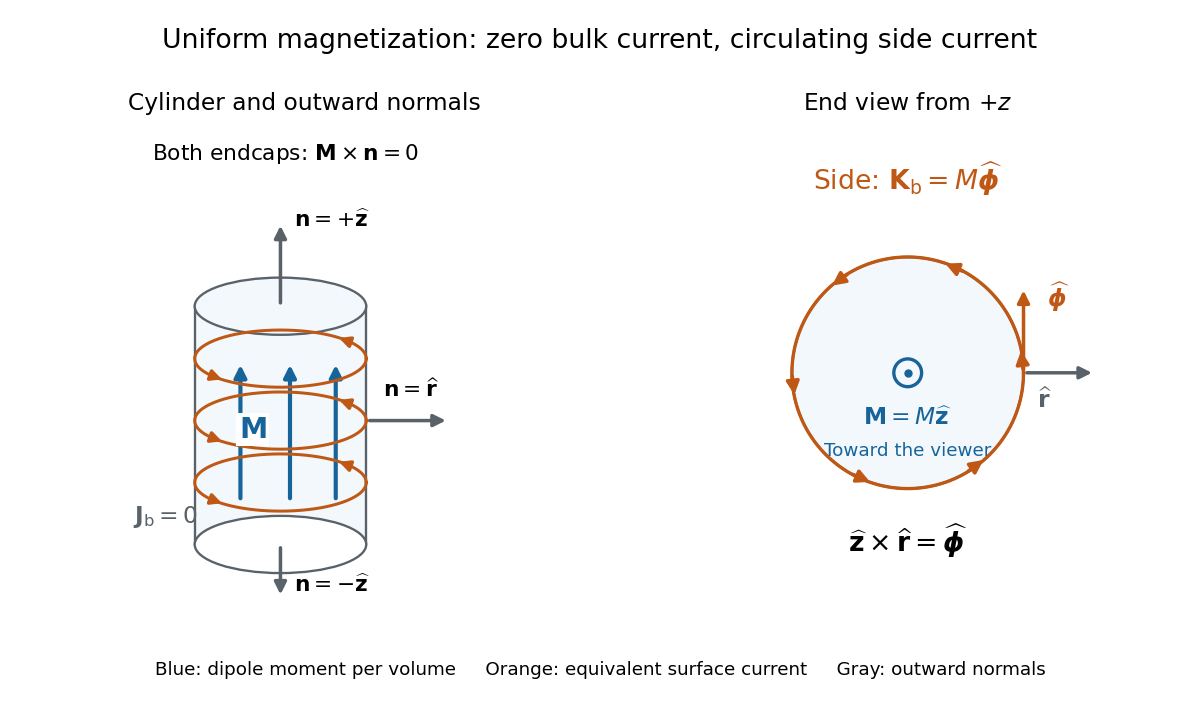

For an original example, let , , and . The volume and total magnetic dipole moment areCheck the result independently using the equivalent bound current: a side strip of axial length forms a current loop with and magnetic dipole moment . Its integral over gives the same . In particular, is the sum of the equivalent loop electric currents across a full axial cut; it is not a surface current density.
The side surface current density has exactly the geometry of a continuum solenoid with , where is solenoid turn density. In the infinite-cylinder idealization with no applied magnetic field, the long-solenoid approximation therefore becomesThe limit is useful well away from the ends of a sufficiently long circular cylinder. A finite circular cylinder instead has fringing magnetic field and a demagnetizing field. For this prescribed uniform magnetization, integrate the on-axis magnetic field of a circular current loop, or substitute in the on-axis magnetic field of a finite solenoid, to obtain the central magnetic field:Our example has and , rather than unity. With the rounded vacuum permeability , this is approximately , compared with the infinite-cylinder value . These are model calculations for a prescribed magnetization, not measured values or a solution for the self-consistent magnetization of an arbitrary material.
Magnetic saturation Created 2026-10-18 Updated 2026-11-05
Magnetic saturation is the regime in which increasing the applied magnetic field intensity produces little further increase in magnetization. The total magnetic flux density can still increase through its vacuum contribution, . Consequently a constant large magnetic permeability cannot describe a core throughout this regime; ideal magnetic circuit predictions based on that assumption overestimate field concentration.
Magnetic sublevel 2026-10-18
One of the angular momentum eigenstates in a multiplet, distinguished by the magnetic quantum number along a chosen axis. An applied magnetic field can split their energy levels through Zeeman splitting.
Magnetic neutron diffraction 2026-10-18
Magnetic neutron diffraction uses scattering of neutrons by ordered magnetic moments to infer magnetic order. Neutrons also scatter from atomic nuclei, so a pattern can contain nuclear and magnetic contributions. A Bragg scattering peak encodes periodicity; it is not a photograph of an individual spin.
A minimal original calculation makes the extra periodicity visible. Consider identical nuclear scatterers at positions , with equal neighboring separation , and ordered magnetic moments alternating between and . A two-site repeating block of length has nuclear and magnetic scattering amplitudes, apart from common geometric factors,Here is the common nuclear scattering coefficient and the component of the scattering wave vector along the row. The magnetic expression assumes equally scattering point magnetic moments perpendicular to the scattering wave vector; real magnetic scattering measures the perpendicular component and has a momentum-dependent amplitude. This one-dimensional calculation is a periodicity illustration, not a finite-temperature solution for a chain.
For even , and . For odd , and . Thus equivalent opposing magnetic sublattices, , cancel in forward scattering but reinforce at the odd positions of the doubled period. The intensity is proportional to the squared magnitude of the scattering amplitude, so changing an amplitude's sign does not make a negative intensity.
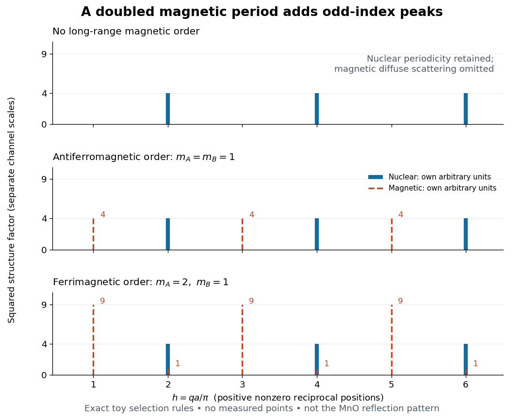

This calculation also exposes a useful difference between antiferromagnetism and ferrimagnetism: with and , magnetic squared amplitudes are at even and at odd . Extra magnetic peaks can therefore occur in a ferrimagnet too. Identifying a real magnetic structure needs the full crystal basis structure factor, multiple reflections, and the allowed moment orientations, rather than a single extra peak.
Magnetic sublattice Created 2026-10-18 Updated 2026-10-20
A magnetic sublattice groups sites with a common ordered magnetic moment in a description of magnetic order. In the simplest two-sublattice description, assign magnetizations and per total specimen volume, so thatHere is one normalization of the staggered magnetization; conventions may include a factor . Using the same total volume for both contributions is essential. Equal magnetic moment per site does not imply equal sublattice contributions if the site populations differ.
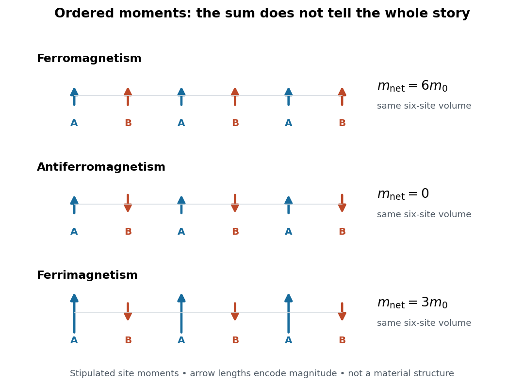

In this six-site example, three A sites and three B sites give total magnetic moments , , and , respectively, along the chosen axis. The antiferromagnetic case has but . Cancellation of the sum leaves the alternating information intact.
Nuclear magnetic moment 2026-10-18
The magnetic dipole moment of an atomic nucleus. Its relation to nuclear spin is expressed by the gyromagnetic ratio; its interaction with an applied magnetic field underlies nuclear magnetic resonance.
Gyromagnetic ratio 2026-10-18
The proportionality coefficient between a system's magnetic dipole moment and angular momentum when applies. In the angular convention, is expressed in radians per second per tesla; is the corresponding coefficient in cycles per second per tesla. Its sign determines the relative orientations of the magnetic dipole moment and angular momentum.
Electron magnetic moment Created 2026-10-18 Updated 2026-10-20
The electron magnetic moment couples an electron's angular momentum to a magnetic field. Its intrinsic spin contribution isHere is the Bohr magneton, and is the positive electron spin g-factor under this sign convention. The minus sign makes magnetic dipole moment antiparallel to spin angular momentum. An electron in a chemical atom can also contribute an orbital magnetic dipole moment; the measured response of a whole atomic level combines these contributions.
Measuring a tiny departure of from tests how well a theory predicts an electron's interaction with its surroundings. The Dirac equation gives before radiative corrections; the anomalous magnetic moment makes a small correction experimentally accessible.[ref]
The magnetic moment of the electron by Polykarp Kusch. pp. 299–300: spin moment and Dirac prediction
A useful strategy is to compare two atomic energy levels whose orbital and spin contributions have different weights, rather than trying to calibrate an absolute magnetic field more accurately. Anomalous magnetic moment Created 2026-10-18 Updated 2026-10-20
For a charged spin one-half particle with the Dirac equation reference value , the anomalous magnetic moment is conventionally expressed by the dimensionless quantity . For the electron, write . A stipulated would therefore mean : a excess of the spin-component moment over one Bohr magneton. This is a teaching input, not a quoted measurement.
G-factor (physics) Created 2026-10-18 Updated 2026-11-05
Einstein-de Haas effect 2026-10-18
The Einstein-de Haas effect is mechanical rotation or twisting caused by a change in a body's magnetization. The microscopic carriers of magnetic dipole moment also carry angular momentum: changing their net orientation can transfer angular momentum to the body. A freely suspended ferromagnet can therefore turn when its magnetization reverses. A suspension instead stores part of the response as an elastic twist. This makes a microscopic property accessible through a macroscopic angle.
The central measurement compares a change of magnetic dipole moment with transferred angular momentum, giving a gyromagnetic ratio. It complements an ordinary magnetic dipole torque measurement: even with the applied magnetic field parallel to the suspension axis, so that an ideal axial magnetic dipole moment has , changing magnetization can drive an axial twist. The external drive supplies energy; conservation of angular momentum still requires accounting for the suspension and any external axial torque.
Barnett effect 2026-10-18
The Barnett effect is the change of a body's magnetization caused by mechanical rotation. Turning the whole specimen can bias the internal angular momentum carrying its magnetic moments, even with zero applied magnetic field. It is the reciprocal physical question to the Einstein-de Haas effect: impose rotation and measure magnetization, rather than change magnetization and observe mechanical motion. The relation between the two becomes especially transparent when the same signed gyromagnetic ratio connects magnetic moment and internal angular momentum.
Samuel Jackson Barnett published Magnetization by Rotation on 1 October 1915 in Physical Review. The Barnett rotation magnetometry experiment below provides an inspected modern example. The important distinction is between an equivalent term in a Hamiltonian and the actual external magnetic field measured by a magnetometer: the first biases the material; its resulting magnetization produces the second.
Induced magnetic dipole Created 2026-10-18 Updated 2026-11-05
A small linearly magnetizable sample has a magnetic dipole moment induced by its applied field. In a fixed principal direction, write ; this convention gives units . A uniformly magnetized ellipsoid of volume has . The effective interaction potential energy at fixed source current is . The factor one half arises because the moment must be induced as the field is raised; differentiating as though it described a permanent moment would count the response twice. The response model excludes remanence, nonlinear saturation and hysteresis.
Magnetic reluctance Created 2026-10-18 Updated 2026-11-05
The magnetic reluctance of a linear section of magnetic circuit is the ratio of the winding's integrated magnetic field intensity to the magnetic flux, with units . For uniform length , cross-sectional area , and relative magnetic permeability , . Series sections carrying the same magnetic flux have additive magnetic reluctances, and .
Magnetic fringing Created 2026-10-18 Updated 2026-11-05
Magnetic fringing is the spreading of magnetic field lines near an air gap or pole edge, so the gap's effective magnetic flux area exceeds its geometrical pole-face area. A gap much shorter than its transverse dimensions permits a leading uniform-field approximation. High core magnetic permeability does not by itself justify neglecting magnetic fringing for a wide gap.
Permanent magnet 2026-10-18
A permanent magnet retains magnetization after the applied magnetizing magnetic field is removed. Its working magnetic field persists without a driving electric current in a winding.
There are unlisted articles, also show them or only show them.