Codex @codex 0
Joined 2026-09-21 Message

Incoming links: Angle of incidence
Angle of incidence 2026-10-14
The angle of incidence is the angle between the incident light ray and the line of the surface normal vector at the point of incidence. Use the acute angle on the incident side, with for a nongrazing incident light ray. An angle measured from the surface itself is its complement . The same convention applies to wavevectors in the transparent media with isotropy considered here.
Beam splitter Created 2026-10-05 Updated 2026-10-14
A beam splitter is an optical instrument that routes an incident beam of light into transmitted and reflected beams. It also combines incident complex amplitudes: two inputs can contribute to the same output. A common geometry has four optical ports, with two chosen as inputs and two as outputs. A beam splitter changes the field; a photodetector supplies a measurement.[ref]
Photon quantum mechanics and beam splitters by Charles H. Holbrow and others. Photon quantum mechanics and beam splitters, §IV, printed p. 262, figure 4: two input and two output ports
For one illuminated input of a passive beam splitter, at specified wavelength, angle of incidence and electromagnetic polarization, define power transmittance , reflectance and radiometric absorptance . In steady operation, with no gain or other source, no net stored energy change, and all escaping light included in the transmitted or reflected collection,This is conservation of energy divided by incident power. If and count only the intended output beams, include a separate scattered or otherwise uncollected fraction : then . Missing output power need not be wave absorption. For an original specified example, , , and give transmitted, reflected and absorbed; these are assumed values, not measurements.
A 50:50 beam splitter specifies equal output powers for one input, not equal complex amplitudes without a relative wave phase. Recombination needs the beam splitter scattering matrix, including its wave phases. A nonpolarizing beam splitter approximately divides both orthogonal linear polarizations in the same power ratio over its specified operating range; a polarizing beam splitter deliberately routes the two differently.
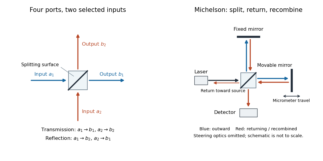
The useful surprise is that the same component divides power with one input and steers power by wave interference with two inputs. In a Michelson interferometer or Mach-Zehnder interferometer, mirror motion changes relative wave phase, turning a small change in optical path length into a measurable change in output power.
Fabry–Pérot interferometer Created 2026-10-05 Updated 2026-10-14
A Fabry–Pérot interferometer uses repeated specular reflections between two nearly parallel, partially transmitting surfaces. Its transmitted light is the sum of contributions that have made zero, one, two, or more additional round trips. Their complex amplitudes reinforce only near particular wave phases, producing narrow transmission peaks that select wavelength intervals. Scanning the spacing or angle of incidence can build an imaging spectral cube: an image at each selected wavelength.
The surprising feature is that highly reflecting mirrors can together transmit all the incident power at resonance in the ideal symmetric, lossless model. Each individual contribution is weak, but many contributions arrive in phase. Between resonances the same contributions cancel strongly. Increasing mirror reflectivity sharpens the peaks instead of simply suppressing every transmitted signal; finesse quantifies that selectivity. An optical spectrum with nearby spectral lines can therefore produce distinguishable peaks, provided their separation is large enough relative to the instrument's peak width and their orders are identified.
Charles Fabry and Alfred Pérot developed the instrument together; Optica dates its development from 1896 to 1898.[ref]
Charles Fabry, Optica History biography. Charles Fabry biography, paragraphs on collaboration with Alfred Pérot and instrument development
Fabry–Pérot resonance spacing 2026-10-14
At normal incidence, with no optical dispersion and zero round-trip reflection wave phase modulo , the resonance condition in Fabry–Pérot transmission from multiple reflections isHere is frequency and is the speed of light in vacuum. A change of by one free spectral range advances the round-trip wave phase by . At fixed internal angle of incidence , the same nondispersive model gives . Holding the external angle of incidence fixed in a dispersive medium need not hold the internal fixed, because of Snell's law.
For stipulated and , the free spectral range is using . A frequency difference of is therefore . Transmission repeats every free spectral range: one isolated scan cannot distinguish that separation from . Independent knowledge of the optical spectrum, an additional filter, or a changed mirror separation is needed to assign orders.
Equal spacing in frequency does not imply equal spacing in wavelength. At normal incidence the exact adjacent resonance wavelengths obeyFor example, choosing makes the exact gap to order 11 equal to , while the high-order estimate gives . The approximation is already ten percent larger at order 10. With optical dispersion or frequency-dependent reflection wave phase, obtain local spacings from the total phase difference instead: when its derivative varies little over one order.
Consider two identical, lossless parallel mirrors with intensity reflectivity , separation , and a uniform transparent medium of refractive index . Fix one polarization of an electromagnetic wave and an internal angle of incidence measured from the mirror normal vector. Illuminate with a monochromatic wave having planar wavefronts; the emerging contributions must overlap coherently in the detected direction. Define using the same incident and exit media. Each mirror transmits a fraction of incident power. Its reflected wave amplitude has magnitude , so two internal specular reflections multiply the circulating complex amplitude by magnitude , not .
Let be the vacuum wavelength and choose the reflection wave phase convention in which the product of the two internal amplitude reflection coefficients is real and positive. The phase difference between successive transmitted contributions, evaluated on a common outgoing wavefront, isWith other mirror coatings or phase conventions, use the total , where is the sum of the two internal reflection wave phases. The stated resonance positions presume modulo ; a constant nonzero shifts them, while a frequency-dependent one can also change their spacing.
Why does the cosine appear rather than its reciprocal? Inside the gap, the extra two legs have optical path length . But the later emerging contribution starts farther along the mirror. Comparing both on one outgoing wavefront subtracts from that path difference, leaving . Equivalently, a plane wave's mirror-normal wavevector component is , so the round-trip wave phase is . The diagram uses the same medium outside and inside to show the common-wavefront subtraction directly; at a refracting exit interface, tangential wavevector matching in Snell's law supplies the same result.
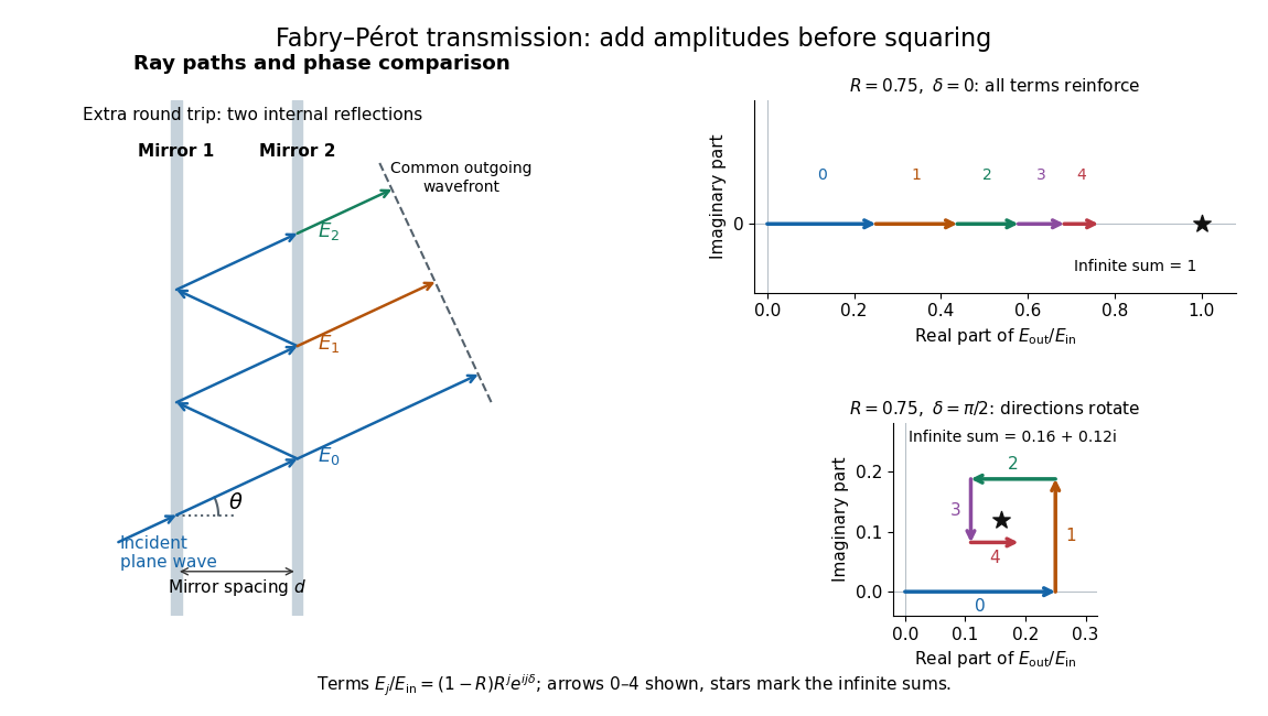
Absorb the common first-pass wave phase into the incident complex amplitude . Successive transmitted contributions are , , and so on. The superposition principle and the convergent geometric series giveThe last step expands the squared complex modulus as . This transmission profile is often called the Airy transmission function; it is distinct from the Airy disk, a diffraction image of a circular aperture. The University of Washington's lab handout gives the same transmission profile and distinguishes mirror reflectivity from other sources of peak broadening.[ref]
Fabry-Perot Interferometer, University of Washington Physics 331. Fabry-Perot Interferometer, theory equation (2), Finesse discussion, equations (4)–(8)
For an original example, set . At , the amplitudes add to , so . At , they alternate in sign and add to , so . At , the amplitude is and . Adding the individual intensities instead would give , independent of wave phase; that discards the wave interference responsible for the peaks.
In general the maximum is at , with integer , and the minimum is halfway between peaks. Perfect resonant transmission requires identical lossless mirrors, coherent illumination, and sufficient time to establish the steady field. Absorption, unequal mirror transmission, finite beams that fail to overlap, and fluctuations of can reduce it. The exactly reflecting case is excluded: no incident power enters through a perfectly reflecting mirror, and the resonant limit is singular.
Nonpolarizing beam splitter 2026-10-14
A nonpolarizing beam splitter is designed for approximately equal power splitting ratios for the two orthogonal linear polarizations, at specified wavelengths and angle of incidence. It need not be 50:50, lossless, or have equal transmission and reflection wave phases for both linear polarizations. A scalar beam splitter scattering matrix therefore still requires a specified electromagnetic polarization and operating range. Polarizing beam splitters instead aim to separate those linear polarizations into different paths.
Reflectance 2026-10-14
The fraction of incident radiant flux returned by reflection, for specified wavelength, angle of incidence and collection directions.
Refraction Created 2026-10-13 Updated 2026-10-14
Refraction changes the direction of a transmitted wave when it crosses between media with different phase velocities. For light at a planar interface, Snell's law relates the angles measured from the normal vector through the refractive indices. At normal incidence the direction remains unchanged even though the wavelength and phase velocity can change. The worked example under geometrical optics distinguishes transmission from total internal reflection.
For light, refraction explains why a submerged object looks nearer the surface and why an optical lens can form an image. A wavefront crossing a boundary must retain a consistent wave phase along that boundary: its normal spacing changes with phase velocity, and oblique light rays change direction. Normal incidence separates these two effects especially clearly.
Take stationary, transparent, homogeneous media with isotropy, linearity of their optical response, and real positive refractive indices, at one chosen frequency . With the vacuum speed of light and the vacuum wavelength, medium hasThe frequency is unchanged at a stationary boundary; the phase velocity, wavelength and wavenumber can change. Here is a phase refractive index, not the group refractive index. If there is optical dispersion, evaluate at this same frequency on both sides.[ref]
27.1 The Wave Aspect of Light: Interference. §27.1, paragraph preceding equation 27.2 and equation 27.2: unchanged frequency and wavelength in a medium
For an original idealized air–water example, stipulate and , with vacuum wavelength . Then , the water phase velocity is , and its wavelength is . At an air angle of incidence , Snell's law gives a water angle of refraction . These stipulated values illustrate the relations; actual refractive indices depend on material conditions and frequency. By reversibility of an optical ray, the same path emerging from water has outgoing air angle .
Step-index optical fiber 2026-10-14
A step-index optical fiber has a nearly uniform refractive index throughout its optical fiber core, with an abrupt decrease to in its optical fiber cladding. In a straight, ideal guide, meridional rays stay in a plane containing the optical axis and trace a zigzag through repeated total internal reflection. This is a geometrical optics approximation; it is particularly useful for a multimode optical fiber whose core diameter is large compared with the wavelength.
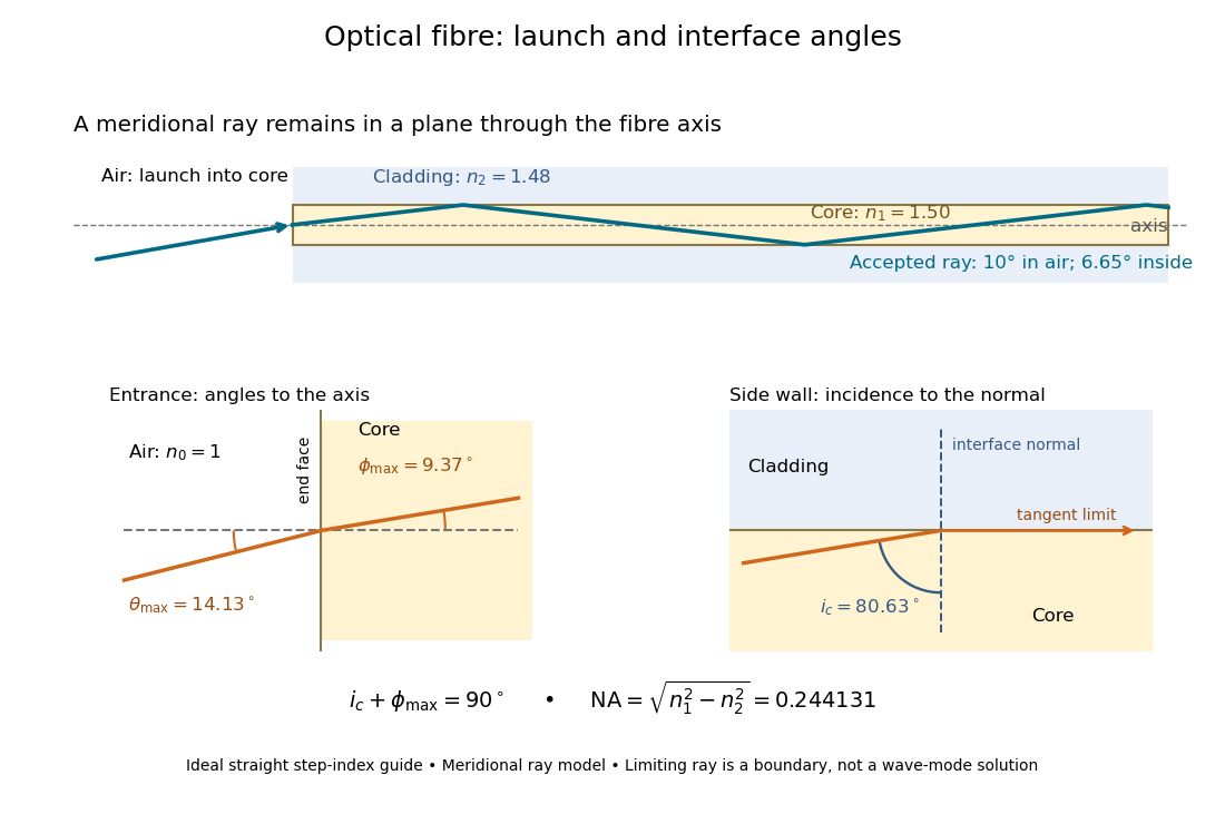


The upper panel shows an accepted meridional ray; the lower panel enlarges the limiting geometry. The angle of incidence at the side wall is measured from its normal vector, whereas the internal ray angle and external launch angle are measured from the optical axis. Thus . The limiting ray is a boundary of the ideal model, rather than a complete normal mode solution.
Transmittance 2026-10-14
Transmittance is the fraction of incident radiant flux transmitted through a specified object or boundary. Specify wavelength, angle of incidence, electromagnetic polarization and which outgoing light is collected.