A nondispersive wave has a linear dispersion relation over the relevant range, so every Fourier transform component has the same phase velocity and group velocity . A wave packet then translates without spreading in an ideal homogeneous lossless medium.
For wave dispersion, depends on frequency or wavenumber. Different components accumulate different phases, and in general the group velocity differs from the phase velocity; variation of group velocity across the spectrum produces spreading of a wave packet. The membrane material can be nondispersive while confinement in a membrane waveguide introduces wave dispersion along its length.
For a fixed transverse normal mode, define its cutoff angular frequency
The longitudinal phase velocity and group velocity, for propagation in , are
Thus , and . The large longitudinal phase velocity reflects the geometry of the transverse standing wave and does not imply faster transport of energy than the membrane wave speed.
The cutoff frequency of a membrane waveguide for mode is
At cutoff and ; the longitudinal phase velocity has no finite value. Below cutoff,
and a bounded field excited at decays as . It is an evanescent wave, rather than a freely propagating mode carrying net time-averaged energy flux down an indefinitely long uniform strip. A finite section can still transmit through coupling of evanescent fields.
State a time convention before using complex response: take fields proportional to , with and for a passive wave entering the material. In a homogeneous Ohmic medium, Maxwell equations with give
The ohmic-conductor complex wavenumber describes both phase advance and amplitude decay. Real constant conductivity is only a low-frequency approximation. In the Drude model, gives
with a fixed positive ionic background and no additional bound-electron contribution in this simple model. The plasma frequency marks the inertial electron-response scale. More elaborate band structure, interband transitions and nonlocal transport limit this scalar treatment.[ref]
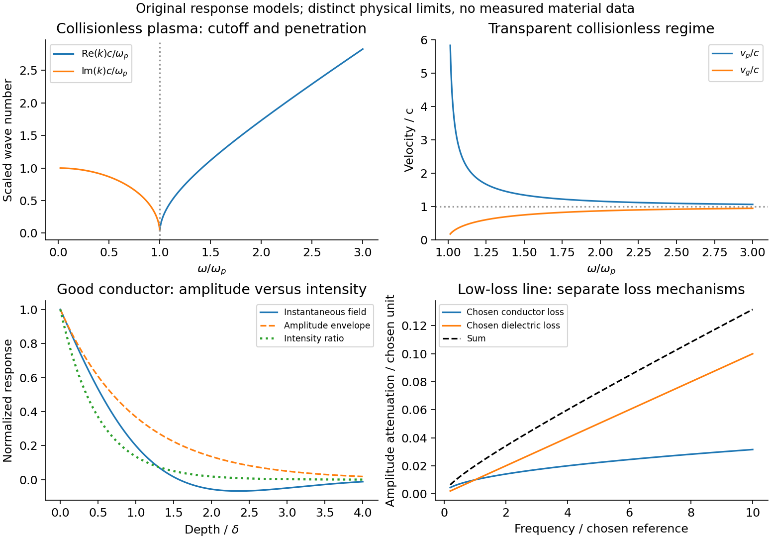
In the collisionless nonmagnetic limit, the dispersion relation is . For ,
A crest can move faster than without carrying a new signal faster than light. Below cutoff the ideal wave is evanescent, with penetration length ; it does not propagate as an ordinary real- bulk wave. Evanescence in the lossless limit is not Joule dissipation. Nonzero collision rate gives a dissipative conductivity and smooths this ideal cutoff picture.
For a good conductor with approximately real , the spatial branch becomes
A field amplitude falls as , while intensity falls as . The phase velocity is in this limit. Magnetic and electric amplitudes are not related by the vacuum ratio: with the chosen time convention. Its positive real part is the surface resistance. The local mean heating is , consistent with electromagnetic energy flowing into the metal. skin depth is an amplitude length; interpreting it as an intensity length gives a factor-of-two error.
A transmission-line mode propagates chiefly through the dielectric between conductors, even though finite metal conductivity causes loss at its boundaries. With per-length parameters , the telegrapher's equations give, for the same convention,
Writing a forward wave as , , gives . In the low-loss regime and , set to obtain
This low-loss transmission-line attenuation separates series conductor loss from dielectric leakage loss. Average forward power falls as . In the normal skin-effect regime, reduced conducting area makes the AC conductor resistance increase roughly as ; dielectric loss can supply a separate frequency dependence. Reflection from a mismatched termination changes delivered power without being, by itself, dissipation in the line.[ref]
To test loss, compare several lengths of otherwise identical line with matched terminations, calibrate connectors and incident/reflected power, and monitor temperature. Separate amplitude attenuation from phase delay and from standing-wave minima. Bulk penetration, line attenuation and dielectric propagation speed are related electromagnetic quantities but describe different experimental geometries.
Figure 1.
Conducting-wave propagation
. Chosen dispersion and decay models. Details.
For a waveguide mode in a homogeneous nondispersive filling, . Its phase velocity is and its group velocity is , giving
Guided electromagnetic waves propagate along a structure whose boundaries select transverse field patterns. At a perfect conductor the tangential electric field vanishes. In a hollow rectangular guide, TE modes have and TM modes have . Their longitudinal wavenumber obeys
Below the waveguide cutoff frequency , that mode is evanescent rather than freely propagating. TM modes require both indices positive; TE modes may have one zero but not both. For , the lowest cutoff is the TE mode, with . A hollow single-conductor guide has no TEM mode, whereas a two-conductor transmission line can support one without this geometrical cutoff.[ref]
For a propagating TE or TM mode, and . The phase velocity can exceed without superluminal information transfer. Frequency-dependent group delay can broaden pulses; excitation of several modes adds intermodal dispersion.
The characteristic impedance of a lossless transmission line is the ratio of the voltage to the current amplitude of a single forward-travelling wave. If and denote inductance and capacitance per unit length, the lossless telegrapher equations give
A backward wave has when current is positive along . Thus characteristic impedance is not a resistor's electrical resistance: it describes travelling-wave amplitudes and determines impedance matching, power transfer and reflections. A semi-infinite line, or a line terminated by a matching load, presents that impedance at its input.
At a junction with no lumped branch, voltage and electric current are continuous:
Eliminating gives the voltage reflection coefficient
For real positive , incident and reflected waves occupy the same line, so their power ratio is .
For the slightly mismatched coaxial cables, the change in characteristic impedance is
Consequently
The requested power limit implies . Since for the stated line, the adjacent cables' outer radii must match within approximately . If a tolerance is quoted separately as a symmetric manufacturing range and arbitrary worst-case pairs can differ by , the corresponding individual tolerance is approximately . The leading calculation is for small mismatches; the exact logarithmic expression gives slightly asymmetric positive and negative limits. The vacuum wave impedance used here is approximately .[ref]
A needle is a shunt electrical resistance , so the load seen at its location is the continuation of the line in parallel with : . The local voltage reflection coefficient and transmission amplitude are
For periodic resistive loading of a transmission line, the reflection from the next needle travels an additional round trip and crosses each previous needle twice. Taking the first needle as phase reference, the single-return approximation for periodic line reflections therefore sums to
Here is the propagation phase velocity in the cable, for the stated nondispersive nonmagnetic filling. Squaring the amplitude gives the requested expression
For a finite number of needles the amplitude has the additional numerator . The displayed semi-infinite result assumes sufficiently many needles, no terminal reflection, and neglects intrinsic propagation loss.
For real , write . The denominator of the power coefficient is . It has constructive peaks at and minima at , repeating with frequency spacing . Within this approximation,
Weak individual shunts thus give narrow interference peaks, with phase width of order .
The requested sum excludes paths that reflect repeatedly between different needles. It should not be read as an exact multiple-scattering result, particularly at the coherent peaks. For example the exact semi-infinite amplitude satisfies
At this equation reduces to : the exact ideal infinite array has unit power reflection there, rather than the first-return approximation's value near . This does not change the requested geometric-series derivation, but identifies its physical limitation.
Displacement current makes Ampère's law compatible with charge conservation. The macroscopic Maxwell equations are
Taking the divergence of the last equation and using Gauss's law gives . Omitting would wrongly require the conduction current to be divergence free during charging. The displacement-current density has current-density units, but need not represent free charges crossing a region.
The surface independence of Ampère circulation during capacitor charging illustrates the need directly. A surface spanning the circuit can cut the wire or pass between the plates. For ideal parallel plates, and
The corrected circulation of is independent of that surface choice. Free conduction current stops at a plate; displacement current supplies the gap contribution.
In vacuum the two time-dependent curl equations support waves. Taking a curl of Faraday's law in a source-free region yields
The corresponding magnetic equation is identical. For a plane wave, and . The fields carry energy through the Poynting flux. Dropping displacement current everywhere would remove these freely propagating solutions.[ref]
In a metal, conduction and displacement compete. For a uniform ohmic material with , constant , and transverse waves,
Use . The dispersion relation and conduction-to-displacement current ratio are
When , with : fields are screened within a skin depth and energy is dissipated by Joule heating. This quasistatic limit neglects displacement current locally compared with conduction; it does not invalidate the full Maxwell law. At sufficiently high frequency, conductivity and permittivity are frequency dependent, so a constant- approximation must be replaced by a material model.
In an unmagnetized cold plasma, electron inertia gives a cutoff. With immobile ions and negligible collisions, and give . For the transverse wave cutoff in a cold unmagnetized plasma, combining this carrier current with vacuum displacement current gives
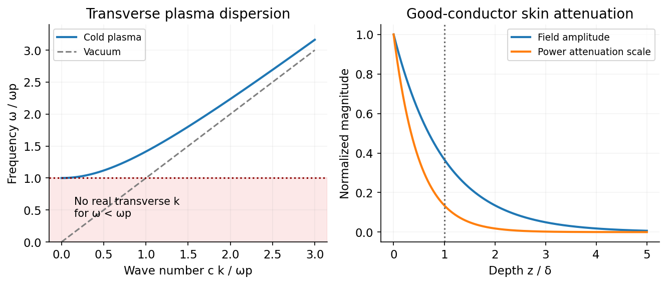
Transverse waves propagate above and are evanescent below it. The group velocity is even though the phase velocity exceeds . The cold model also has longitudinal charge-density oscillations at , distinct from transverse light waves. Collisions add damping, and pressure or magnetic fields modify these simple dispersions. To avoid carrier-current double counting in effective permittivity, once the carrier response is included in it must not be counted a second time as a separate conductivity. Displacement current therefore connects circuit continuity, vacuum radiation, conductor screening and plasma propagation within one consistent field theory.[ref]
Figure 1.
Electron inertia gives transverse plasma waves a cutoff, while a good conductor attenuates fields over a skin depth
. Source. Details.
For a cold, unmagnetized, collisionless plasma, take an equilibrium electron density , electrons of mass and charge , and approximately stationary ions. Use fields proportional to . The electron displacement satisfies
Its electric polarization is , hence the cold collisionless plasma dielectric response
The negative susceptibility arises from the inertial electron response, rather than a restoring force binding an electron to a particular atom.
A transverse electromagnetic wave then obeys
For , the plasma supports propagation, with refractive index . The phase velocity is greater than , while the group velocity is ; their product is , and no superluminal signal is implied. Below the plasma frequency, the bulk wavenumber is imaginary and the field is evanescent. A sufficiently thick plasma largely reflects such radiation in the lossless model.
Including an electron momentum-relaxation rate replaces the denominator by :
Its imaginary part describes absorption with the stated time convention. Finite electron temperature also produces plasma screening of slowly varying electrostatic fields, with . That spatial, longitudinal screening problem is distinct from simply taking in the cold transverse-wave formula. Magnetic bias, ion motion and kinetic resonances require more general dielectric responses.
Assume an air-filled or evacuated lossless electromagnetic waveguide, and a pulse bandwidth narrow enough to use its carrier's local group velocity. The longitudinal dispersion relation is
It gives
Here , so
The phase velocity exceeds , but the pulse envelope travels at the subluminal group velocity; a moving constant-phase surface does not by itself transport information. Their product is . A broad pulse can distort because this waveguide is dispersive.
Electromagnetic waves drive mobile charges in a conducting medium. Their current changes both the phase and attenuation of the wave. A description in terms of a real, frequency-independent refractive index is therefore generally insufficient: the material response and the propagation constant are complex and frequency dependent.
Use phasors proportional to , with and for a passive medium. In a homogeneous, isotropic, linear material, let represent the permittivity associated with bound-charge electric polarization, the magnetic permeability and the mobile-charge conductivity. The macroscopic Maxwell equations give
For a transverse plane wave, taking another curl yields
This division of the response avoids counting mobile electrons both in and in . Define the complex refractive index . For a nonmagnetic medium, . Its real part determines the phase variation, while the positive optical extinction coefficient gives amplitude attenuation and intensity attenuation . The amplitude penetration length is
A simple microscopic explanation comes from the Drude model. Let electrons of charge , mass and number density move against an effectively stationary positive background. Collisions relax their mean velocity at rate :
Consequently
With a vacuum-like bound-charge background, this gives
Its imaginary part is positive for positive , consistent with dissipation under the chosen phasor convention. Real materials can require an effective electron mass, a nontrivial bound-charge response, or additional absorption associated with the electronic band structure.
A plasma is a conducting ionized medium with mobile electrons and ions, approximately neutral on large scales because of plasma screening. For the electron-frequency transverse waves considered here, the heavy ions can often be treated as stationary. In a dilute weakly collisional plasma, , so
For , is real in this collisionless model and the wave propagates. Its phase velocity is , while its group velocity is ; their product is . A phase crest exceeding does not imply superluminal information transport. For , the refractive-index square is negative and
The transmitted field is evanescent rather than a traveling bulk wave. A sufficiently thick collisionless plasma reflects such radiation without Ohmic absorption. Collisions make the response complex and permit absorption. This accounts for a plasma cutoff and, qualitatively, the reflection of some radio frequencies by ionized atmospheric layers. The simple model describes transverse waves; plasmas also support longitudinal collective modes.
In a metal, positive ions usually form a crystal lattice. Mobile conduction electrons occupy states described by the electronic band structure and normally form a degenerate Fermi gas. The conduction-electron density is usually much higher than in a dilute gas plasma. Thus its plasma frequency is commonly in the optical or ultraviolet range, rather than the lower radio-frequency values possible in dilute plasmas. Electron scattering from the lattice, defects and other excitations gives a finite relaxation rate. The distinction is not that every plasma is collisionless and every metal collisional: the controlling ratio for either material is , together with its carrier density and bound-charge response.
At sufficiently low frequency, , the metal's conductivity is approximately real, . In a good conductor the conduction current dominates the displacement current, . The wave equation then gives
For example, a tangential electric field varies as
The current is therefore concentrated within a few skin depths of the surface: this is the skin effect. As frequency increases within this regime, . In a wire whose radius greatly exceeds , only a thin outer region carries appreciable alternating current, increasing the effective resistance. In a conducting shield, the same penetration suppresses the field transmitted through a sufficiently thick wall.
The Poynting theorem identifies the loss as Joule heating. The cycle-averaged heating density for a complex conductivity is
The wave impedance is . For incidence from vacuum at normal incidence, the electric reflection amplitude is , where . A good conductor has small and therefore strong reflection, while the part of the incident power entering it is dissipated over the skin depth.
At high enough frequency that , a metal's free-electron response also approaches the collisionless plasma form. The low-frequency formula must not simply be extrapolated into that regime. Real optical behavior additionally depends on the electronic band structure and transitions between bands. Both plasmas and metals are therefore described by the same electromagnetic response framework, but their relevant densities, scattering rates and frequency regimes differ.
For the propagating mode of an air-filled or evacuated rectangular electromagnetic waveguide, the longitudinal dispersion relation is
The phase velocity and group velocity along the guide are consequently
With waveguide cutoff frequency and carrier frequency , . Thus
The pulse envelope travels at the group velocity for a sufficiently narrow range of frequencies. The phase velocity exceeding the speed of light does not describe superluminal signal transport. The check follows directly from the dispersion relation. A different uniform filling medium would require replacing by its electromagnetic propagation speed; the stated numerical answer uses the usual empty-guide assumption.
The displacement is along , transverse to propagation in the membrane's plane. Write ; then . Here is the displacement amplitude, the initial phase, the angular frequency and the wavevector normal to constant-phase lines. Its magnitude is , and its direction specifies phase propagation for the chosen sign convention.
For equal-phase two-wave membrane modes, two equal complex amplitudes with opposite sum to
The edge condition gives , hence , , for this even-in- family. Opposite relative phase gives the sine family; together they yield all Dirichlet transverse modes , . For the equal-phase family,
The lowest mode has . Therefore
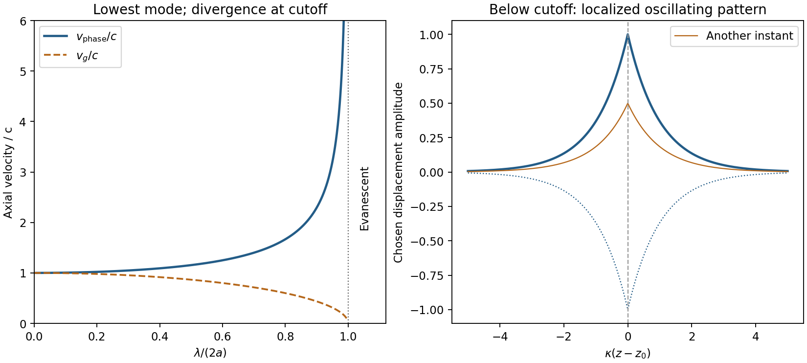
It approaches for and diverges as ; there is no real travelling-mode beyond the cutoff. This is an axial phase velocity, not the group velocity: . Here denotes the membrane wave speed, not the speed of light.
Figure 1.
Membrane cutoff and evanescent response
. Original lowest-mode phase-velocity curve, with group velocity distinguished, and a schematic below-cutoff displacement envelope of exponential form. All lengths and amplitudes are dimensionless choices; no source apparatus drawing is copied. Details.
For the evanescent membrane response below cutoff, below , put for decay along positive , with . A localized central drive creates an evanescent, sinusoidally oscillating deformation decaying away in both axial directions. Far enough from the drive the leading profile is proportional to . Higher evanescent modes contribute near the point source. The pattern has no steadily advancing axial phase front or far-field propagating wave; decreasing frequency increases its spatial localization.
For a flexible uniform string with linear mass density and tension , dimensional analysis gives and hence . The small-slope force balance fixes the factor to one:
Here has units kg/m, not the volume-density units used for a bulk fluid. The phase moves along the string at , while a material point moves transversely with . Its maximum speed is , which is not the phase velocity. Small slope makes in this model.
The kinetic energy and extra elastic energy of a segment are
The second expression follows from extra length against the pre-existing constant tension. Time averaging a harmonic wave gives and . Therefore
At the driven endpoint the string pulls along its local tangent into , with vertical component for small slope. The point exerts the opposite force on the string, so the driven-string endpoint power is
For the outgoing wave , at the derivatives are and . Thus and
The energy flux of a transverse string wave follows by combining the energy density and flux , which satisfy . For a pure right-going nondispersive wave, even instantaneously. energy is transported with the wave; a material string element merely oscillates about its unperturbed position.
At the first two specified times, the displacement profiles are
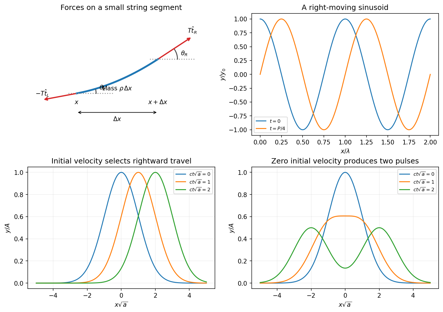
The second curve is the first shifted right by . More generally a point of fixed wave phase satisfies , so it moves along . Hence the wave travels in the positive direction with
This phase velocity is distinct from the local transverse velocity of a string element.
For the force derivation take a short segment between and . Let the tangent angles to the positive axis be and . The left tension pulls along the negative tangent and the right tension along the positive tangent. With small slopes and approximately constant tension magnitude , the horizontal components cancel to leading order and
The segment mass is , where is mass per unit length, not volume density. Newton's second law therefore gives
The approximation neglects bending stiffness, damping and changes in tension caused by finite-amplitude stretching.
Figure 1.
String-element forces, a right-moving sinusoid and two Gaussian-pulse initial conditions
. Details.
Converting the supplied density gives , so
For the pulse, define with . The given initial velocity is , exactly the velocity associated with a right-moving displacement . Therefore
It moves right without changing shape in this nondispersive model. With the same initial displacement but zero initial transverse velocity, D'Alembert's formula instead gives the Gaussian pulse splitting from zero initial velocity
The two half-amplitude pulses travel in opposite directions. Their initial velocities cancel, while their initial displacements add to the prescribed Gaussian. The two initial-value problems have different kinetic energies; splitting into half-height pulses does not contradict energy conservation. These forms assume a string long enough that reflections from its ends have not returned.
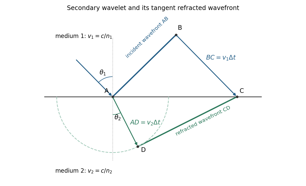
The Huygens-Fresnel principle constructs a new wavefront as the envelope of secondary wavelets emitted by points on an earlier wavefront. Let the phase velocities in the two media be and , with refractive indices evaluated at the light's fixed frequency.
Figure 1.
An original secondary-wavelet construction of refraction at a plane interface
. Details.
For refraction from secondary wavelets, let point of the incident wavefront reach the interface first. A second point reaches the interface at after time , so . During the same interval, the secondary wavelet centered on advances radius into the second medium. The refracted wavefront is tangent to this wavelet, hence ; also because a ray is normal to its wavefront in these isotropic media.
Let be the incident and refracted ray angles from the interface normal. They also equal the corresponding acute angles between the wavefronts and the interface. The two right triangles have common hypotenuse , giving
Their ratio eliminates both and :
This is Snell's law. In particular, entering a medium of larger refractive index reduces the ray's angle to the normal. The construction assumes a stationary interface and homogeneous isotropic media with a propagating refracted wave.
Use base dimensions for mass, length and time. The proposed dimensional analysis gives
so
Equating the independent dimensional powers requires
Consequently
The mass density drops out because there is no other mass-bearing quantity with which to combine it under the stated assumptions.
Dimensional analysis fixes the powers but leaves a dimensionless coefficient undetermined. For a linear deep-water gravity wave, the dispersion relation is , giving phase velocity and group velocity . Both obey the inferred scaling. The phrase wave speed alone does not distinguish these two velocities or fix the coefficient.
The vacuum wave equation gives . The cutoff frequency is . In a lossless empty guide, energy travels at group velocity,
The larger phase velocity is not the speed of energy transport.
Let and . The three branches are
For nonzero and , the zero-frequency mode is stationary geostrophic flow, with and zero horizontal divergence. It carries the linear potential-vorticity disturbance. There is no Rossby-wave propagation on a constant- plane; a varying Coriolis parameter would be needed for that.
The other two branches are oppositely phased inertia-gravity waves. Their phase-speed magnitude and radial group velocity are and . When , gravity dominates: and the waves are approximately nondispersive, with both speeds approaching . When , rotation dominates: , the frequency approaches the inertial frequency and the group velocity tends to zero. The large long-wave phase speed is not a large signal speed.
Without rotation the propagating branches become nondispersive gravity waves, , and the stationary branch is a nondivergent vortical velocity disturbance rather than a finite-pressure geostrophic balance. At , the modes reduce to constant interface height and spatially uniform inertial oscillations. The wave branches have zero linear potential-vorticity perturbation; it is the stationary branch that retains the initial potential vorticity.
Work with the explicitly corrected reduced-pressure system in b. Write and use the complex wave amplitude, taking real parts at the end. The vertical factor satisfies , so the wave equation gives
For a Kelvin wave, continuity, zonal momentum and the buoyancy equation then determine all polarizations:
In particular have amplitude proportional to , whereas pressure has amplitude proportional to . Directly substituting these expressions into vertical momentum gives , verifying both the sign and the dispersion relation.
Meridional momentum is . Since , it integrates to a Gaussian . Thus
The eastward intrinsic branch is selected by decay away from the equator; choosing would make the meridional amplitude grow without bound. Although the squared dispersion relation has both frequency signs, a meridionally trapped Kelvin wave has this one phase-propagation direction.
For short vertical wavelengths, , so , and . The wave is a slowly oscillating, hydrostatic internal gravity wave with strong vertical variation and relatively narrow trapping. Here and ; the buoyancy expression above remains valid.
For long vertical wavelengths, , the exact limiting speed is . To obtain the stated height-controlled limit also requires long horizontal wavelength, . With both and ,
The finite density scale height prevents the hydrostatic phase speed from diverging as . The polarizations tend to , and . Long vertical wavelength alone at fixed large would not justify . In the opposite horizontally short limit the frequency approaches instead. The growth compensates decreasing reference density in wave-energy density; a radiating wave train is a local modal description, not a finite-total-energy eigenfunction over an infinite vertical domain.
Apply the intended, corrected dispersion relation in c. A uniform mean zonal wind gives . Stationarity with therefore requires eastward intrinsic phase speed . With ,
The period determines and . Hence
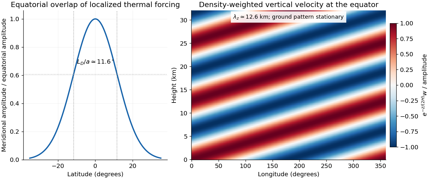
Figure 1.
Equatorial trapping and vertical phase of the stationary Martian Kelvin-wave example
. The original calculation uses an eastward intrinsic speed of 20 metres per second. The Gaussian amplitude has a latitude scale of 11.6 degrees; the density-weighted vertical velocity has a vertical wavelength of 12.6 kilometres. The plotted negative vertical wavenumber corresponds to upward intrinsic energy propagation. Details.
A storm within roughly of the equator has substantial projection on the Gaussian mode. There is no sharp latitude cutoff: gives amplitude and the amplitude latitude is about . Forcing outside that core has progressively weaker overlap.
The intrinsic wave is eastward even though its observed ground pattern is stationary; westward advection cancels its phase propagation. Its intrinsic period is about Earth days. The inferred puts it in the short-vertical-wavelength branch, well below the long-wave speed . For upward energy radiation, must be positive, which selects for positive : vertical phase propagation is then downward. Dust absorption supplies thermal forcing with a zonally asymmetric component; the response does not imply that dust itself moves eastward at the intrinsic phase speed.

Southern spring to summer, the warmer perihelion-side dust season, is a reasonable climatological window for such a regional storm. This seasonal inference uses observed dust climatology, not the dispersion relation: the specified wind and wave parameters alone do not determine a unique season, and individual regional storms can occur outside that window.[ref]