Topics (384k) Articles (398k) Users (410) Discussions (242) Comments (383) Files (13k) New article

Separate spectral-calibration gains in isotope stiffness inference arise when the two Raman spectra retain different multiplicative calibration errors. Let the corrected wavenumbers satisfy . For , small residual gains giveThe relative calibration error in an isotope-corrected stiffness ratio article treats the accompanying offset terms. Here the important quantity is the gain difference, not either gain alone.
If the two residual gains have standard uncertainties and correlation , their contribution isThis follows by applying the full covariance propagation rule.[ref]
Guidelines for Evaluating and Expressing the Uncertainty of NIST Measurement Results by Barry N. Taylor and Chris E. Kuyatt. Appendix A, equation A-3
A shared scale component cancels; independent session errors do not. The covariance of differential spectral-calibration gains therefore determines whether combining calibrations improves the ratio.For an original example, let . Independent calibrations give relative uncertainty about in . A justified correlation reduces it to about ; a correlation instead gives about . These are different calibration models, not alternative ways of adding the same independent errors.
A practical comparison can measure the same known reference line during each sample session. If raw readings are and reference readings , a purely multiplicative model givesBoth session gains cancel, but reference-reading noise, offsets and drift between reference and sample readings remain. Repeated readings do not automatically reveal an unknown common bias.
The primary graphene isotope experiment compared Raman bands over isotope concentrations and excitation energies, finding the harmonic-oscillator mass dependence.[ref]
Probing carbon isotope effects on the Raman spectra of graphene with different ¹³C concentrations by Bruno R. Carvalho and others. Abstract, isotope-mass dependence of Raman frequencies
The calibration model above concerns precision of the inferred residual stiffness ratio; it does not validate mode assignment or the effective-mass approximation.For reference-assisted spectral offset separation, the corrected estimate depends on the measured sample change , reference change and sensitivity ratio . Its measurement uncertainty must include their joint variation, including uncertainty in a fitted sensitivity ratio. Subtracting a reference can reduce shared noise while adding independent noise.
The gradient of the measurement model with respect to is . If is their covariance matrix, first-order uncertainty propagation gives , orThe signs follow from the sensitivity coefficients, rather than a rule that all correlation reduces uncertainty. This is an application of the correlated-input propagation law in the primary GUM.[ref]
Evaluation of measurement data — Guide to the expression of uncertainty in measurement by JCGM. Section 5.2, equations (13)–(15), correlated input quantities
For an original independent-input example, take , , , , and . Then andTreating as exact would give only . A large reference response amplifies uncertainty in its conversion ratio, even when that response is measured precisely.
For mutually independent random inputs, the exact product variance also includes :where on the right denote the input means. It follows by expanding . This term is omitted by linearization. In the example it changes the standard uncertainty to about .
Experimentally, use paired sample/reference spectra to estimate shared covariance, and independent sensitivity measurements to test the proposed value of . If the same spectra estimate both and the correction, independence cannot simply be assumed. Drift between acquisitions or a nonlinear reference response is a measurement model problem as well as a precision problem.
Range restriction in singular-covariance spectral fitting requires a residual to lie in the subspace where the measurement model allows random error. Let with zero-mean error covariance . Every vector in the kernel of satisfiesso almost surely. Thus a permissible residual obeyswhere is the Moore-Penrose inverse. The matrix is the orthogonal projector onto the range of the covariance.
Only after enforcing this condition should a generalized least squares objective use . The quadratic form alone assigns zero penalty to the forbidden directions and therefore cannot impose the condition. Rank deficiency from deterministic spectral upsampling gives its physical spectral-grid origin through . Covariance propagation preserves those exact dependencies.[ref]
For an original idealized two-channel example, take , mean and observation . The second channel has no random error in this stipulated model, so the range condition forces . The remaining squared residual is one. Minimizing only the pseudoinverse quadratic would instead choose and objective zero, while predicting the impossible second-channel value six.
Real measurements need not contain a perfect channel: deterministic rebinning produces exact noise-free combinations of otherwise noisy channels. Additional physical noise in such a combination must be modelled if present. If covariance ranges change with the parameters, pseudoinverse fitting with a parameter-dependent covariance range requires enforcing the appropriate support for each candidate; a single fixed projection need not apply.
Raman detector-array spectra are recorded before numerical redistribution onto another spectral grid.[ref]
Femtosecond Broadband Stimulated Raman: A New Approach for High-Performance Vibrational Spectroscopy by David W. McCamant and others. Instrumentation, array detection; Data Collection, equation 4
Fitting the original independent measurement coordinates often makes these support restrictions explicit and avoids treating interpolation points as new observations.A minimum-variance spectral contrast orthogonal to a reference shape estimates a desired signal amplitude while exactly rejecting one fixed nuisance shape. Let , with known shapes and a positive-definite noise covariance matrix . Choose to minimize , subject toThe constraints retain unit signal response and reject the reference amplitude, as in projection of shared-scale uncertainty onto a spectral contrast. The quadratic variance includes the full noise covariance.[ref]
Remove the reference component in the inverse-covariance geometry:For nonzero and , the minimizing contrast and its variance areFor a short proof, every other feasible contrast is with . Since is a linear combination of those shapes, the cross term vanishes, leaving the added nonnegative variance . This is a constrained best linear unbiased estimator.
In an original three-channel example, take , and . The optimum is , with variance . Equal subtraction of the two reference channels, , has variance . The quieter third channel receives more of the subtraction.
If the desired and reference shapes are proportional, and no unit-response rejecting contrast exists. The noise penalty from nearly parallel signal and reference shapes already becomes large as approaches zero. This construction assumes fixed known shapes and covariance; estimating them from the same noisy spectra requires additional uncertainty terms.
Finite inverse moments in thickness models determine whether a positive but uncertain layer thickness permits a finite mean or variance after conversion to density. With fixed positive mass and area, write , where . A finite thickness mean does not ensure that or exists.
Suppose the thickness probability density function behaves near zero as with . The small-thickness part of the inverse moment is proportional toFor , this converges exactly when . Thus a finite mean density requires , while finite density variance requires , assuming the rest of the distribution is well behaved.
An exact example uses a gamma distribution with shape and scale . Substitution into its density and the gamma function integral givesThe distribution and parameter conventions are specified by NIST; the inverse-moment calculation here follows directly from the integral.[ref]
NIST and SEMATECH e-Handbook of Statistical Methods. §1.3.6.6.11, Gamma Distribution: density and gamma-function definition
For and , mean thickness is and mean density is , yet its second moment diverges. A simulation can return finite sample variances without establishing a finite population variance.A lognormal distribution provides a different positive-tail model. If , then , finite for every finite positive . NIST defines this logarithmic-normal parameterization and its coefficient of variation.[ref]
NIST and SEMATECH e-Handbook of Statistical Methods. §1.3.6.6.9, Lognormal Distribution: parameterization and Common Statistics
With mean thickness and coefficient of variation , mean density is . At , it exceeds by 4%.Tail-model dependence of inferred density uncertainty is therefore experimentally consequential. Choosing a convenient positive distribution changes the implied inverse moments. Justify near-zero behaviour from dimensional evidence or physical bounds rather than treating positivity or a stable finite simulation as sufficient validation.
The photoelastic fringe order expresses the magnitude of the full relative phase retardation between two principal optical components in cycles:For a uniform specimen obeying the linear stress-optic law, , where is thickness and is the photoelastic fringe value. The order is dimensionless and need not be an integer. One unit means one additional complete relative-phase cycle, not a separate stress component.
The connection to a visible fringe depends on the optical arrangement. For ideal crossed linear polarizers and a uniform retarder with optical axes at angle to the incident polarization, the transmitted intensity satisfiesHere is the intensity entering the specimen after the first polarizer, and denotes the full relative phase. At , integer orders are dark and half-integer orders are bright. At axis alignment , the image is dark for every order. The crossed-polarizer derivation therefore separates retardation-related extinction from axis-alignment extinction.[ref]
Experimental Strain Analysis by David Roylance. Printed pp.6–8, stress-optical law, analyzer transmission and extinction mechanisms
For an original ambiguity example at45°, orders0.25,0.75 and1.25 all give . With and , they correspond to stress-difference magnitudes1,3 and5MPa. Brightness alone does not choose among them. Referencing an unloaded state and tracking changes continuously during loading can supply information for photoelastic phase unwrapping.
The primary Illinois apparatus makes these controls concrete: a leadscrew loads the specimen, a load cell records force, monochromatic light and polarizing elements reveal the pattern, and a camera records it. Its magnitude-observation setting uses quarter-wave plates to remove the direction-related fringes.[ref]
Polariscope and Photoelasticity by the University of Illinois Mechanical Testing Instructional Laboratory. Loading and readout; direction/magnitude settings and quarter-wave plates
That changes the observation geometry but does not remove the need to establish absolute order.An order map under a known photoelastic fringe value gives principal-stress difference in the stated specimen model. It does not by itself give the two stresses individually or the sign of the stress-optic coefficient. Wavelength, initial retardation and the through-thickness stress model remain part of the interpretation.
Known-input calibration of a pulse detector uses a characterized optical waveform to separate the incident signal from the receiver response. In a linear, baseline-corrected model,where is known input power, a normalized impulse response and the overall responsivity. Recording the complete response givesThus a known reference energy calibrates the area gain without requiring the input to be an ideal impulse. Shape calibration additionally uses the reference waveform.
For nonnegative normalized profiles with finite second moments, define and . Since , their temporal variances satisfy . In an original chosen example, an input standard deviation and recorded deviation imply . Treating that finite input as a delta impulse would incorrectly assign the full to the detector. This finite-input correction in pulse-detector calibration concerns standard deviations; a universal subtraction rule for arbitrary FWHM values does not follow. Negative ringing also invalidates the nonnegative-profile interpretation used for the variance identity.
NIST's primary procedure illuminated the detector with a pulse much shorter than the detector response and characterized detector, cable and oscilloscope together at the relevant gain and signal levels.[ref]
Calibration Service for Low-level Pulsed-Laser Radiometers at 1.06 µm: Pulse Energy and Peak Power by Rodney W. Leonhardt. §§6.1–6.2; Appendix C.1–C.2, printed pp. 36–37, Figure C1 and measurement procedure
Such a known input breaks the optical tail and detector-response ambiguity described by the parent article.In the frequency domain, the same model is . Division can estimate where the input spectrum is known and sufficiently nonzero; small input components amplify measurement noise. A short reference pulse is useful because it excites a broad frequency range, but detector linearity, baseline, area coverage and reference uncertainty still need checking.
A pressure-map information matrix quantifies which coefficients of a modeled contact pressure field are constrained by a sensor array, relative to its measurement noise. For with fixed positive-definite error covariance , defineHere is the noise-whitened pressure sensing matrix. Whitening removes the output-noise covariance from the residual metric; the primary SciPy covariance interface documents this transformation and demonstrates near-identity covariance on simulated observations.[ref]
The matrix is positive semidefinite because . Its null space is exactly the null space of : an unobserved pressure change remains unobserved after invertible row whitening. With independent Gaussian errors of known covariance, the log likelihood is a constant minus . Differentiating twice with respect to gives negative Hessian , identifying it as the Fisher information for this stated model.
If has full column rank, weighted least squares givesThis covariance follows by substituting and multiplying the error matrices. It concerns the unconstrained linear estimator with known response and covariance, not every reconstruction algorithm. Nonnegativity constraints, regularization and uncertain sensitivity kernels require additional treatment.
An original two-cell example begins with one average-pressure measurement, , with standard error. In numerical kilopascal coordinates,Its eigenvalues are and zero: the mean is observed, but the pressure difference is not. A second independent copy doubles the information matrix while leaving the difference unobserved. More repeats of the same mixture improve precision only in the already measured direction.
Instead add a direct measurement of the first cell with the same independent error. NowThe inferred first-cell pressure has standard deviation and the second . Their errors are negatively correlated because the second pressure is reconstructed by subtracting the first from twice the measured mean.
A rank-one update of pressure-map information follows when an independent new channel has sensitivity row and error variance : its added information is . A channel aligned with a weak pressure direction can therefore be more useful than another precise copy of a strong direction. Correlated new errors cannot be added by that independent-channel formula.
A proposed characterization uses repeatable known loading patterns to estimate , independent repeats to estimate , and withheld patterns to test predicted reconstruction covariance. State the pressure basis and units: rescaling a coefficient changes the numerical information entries. A sharp reconstructed image or a large matrix determinant alone does not establish that the underlying response model or noise assumptions are correct.
Heterodyne amplitude-versus-power gain conversion translates a calibration of measured electric power into a calibration of beat-current amplitude. In a fixed resistive load, power is quadratic in current amplitude, so a multiplicative power correction becomes a square-root amplitude correction. The electrical reference plane and peak-versus-root mean square convention must also agree.
For sinusoidal load current and resistance ,For two measurements of the same load, . A power multiplier of four therefore means an amplitude multiplier of two. In decibels, the same change is dB. NIST distinguishes the factor ten for power ratios from the factor twenty for field-amplitude ratios when their quadratic relationship applies.[ref]
If the load resistance also changes, the more general relation isFor frequency-dependent complex impedances, use the appropriate circuit and power model rather than replacing resistance by an arbitrary complex number. A measured electric potential difference likewise requires its stated impedance before it can be converted to current.
For a corrected detector-current peak amplitude , the normalized overlap is . If the numerator is instead detector-current RMS amplitude, the denominator is . Using an RMS numerator with the peak denominator lowers the result by , a 3.0103 dB discrepancy under the amplitude-ratio convention. The mistake is a convention mismatch, not evidence of worse optical overlap.
Current-plane convention in heterodyne calibration is another independent issue. In an ideal matched Norton circuit, a source peak current splits equally between source resistance and equal load resistance . Load peak current is , so delivered power is , rather than . The factor depends on the specified equivalent circuit; real detector capacitance and interconnecting networks require their measured response.
NIST's two-laser receiver apparatus measures microwave power and separately corrects sensor calibration, network loss and impedance mismatch. Its matched optical modes make the modulation calculable, while the electrical corrections locate the power at the intended reference plane.[ref]
Frequency response metrology for high-speed optical receivers by Paul D. Hale and others. PDF pp. 1–2, Heterodyne measurements, Eqs. 1–4 and Fig. 1
Record raw power, correction factors, reference plane, load, amplitude convention and DC-current calibration separately. Only then apply the gain-matching condition for heterodyne normalization.The gear mesh active-contact set identifies the tooth pairs that carry positive compressive normal force in a specified contact model. It is not simply the set of geometrically overlapping teeth from the gear contact ratio. A pair touching at zero force is excluded under the positive-force convention used here.
For unilateral linear contacts,Here is the initial gap, the pair stiffness, and the common approach. For a proposed nonempty set , force balance givesA gear contact-set consistency check then verifies for included pairs and for excluded ones. Solving the linear equation without this check can retain a negative force or omit a contact that should engage.
An original three-pair example uses stiffnesses and gaps . At total load , the set gives approach and forces . This set is consistent.
At , keeping only those two contacts would give approach , beyond the third gap. Including all three instead givesand forces approximately , which sum to . The third gear tooth engagement threshold occurs at total load .
Within a fixed active set, gear mesh tangent stiffness is the sum of its pair stiffnesses. At a transition, force can remain continuous while that derivative changes. For positive total load the scalar force law is strictly increasing after the first contact, giving a unique approach in this model; the unloaded state need not specify one unique separation.
Real deformation, local contact nonlinearity and dynamics can require more than one common-approach coordinate. A primary NASA analysis coupled tooth stiffness with dynamic-load calculations over contact position and speed.[ref]
Predicted Effect of Dynamic Load on Pitting Fatigue Life for Low-Contact-Ratio Spur Gears by David G. Lewicki. Summary and Introduction, printed p. 1, stiffness–load iteration and contact-position dependence
The active-set calculation is an explicit quasistatic model, not a substitute for that fuller mechanical description.Readout overhead in Raman exposure allocation is the detector time that consumes the acquisition budget without collecting useful probe/reference photons. For pump-on/off exposure pairs, let each frame require a fixed closed-shutter readout duration . A wall-clock budget leaves total live timeUnder the stationary-rate, independent shot noise model of exposure-time allocation for a Raman gain ratio, its minimum approximate relative variance at fixed isReadout changes the available live time, but not this optimum ratio when the overhead is fixed and independent of the on/off allocation. The live-time formula itself ceases to describe all constraints when exposures hit saturation limits or the number of pairs is variable.
The 2003 primary stimulated-Raman experiment used 97 ms exposures and 10 ms detector readout with the exposure shutter closed. The pump shutter switched state during readout, giving successive on/off measurements.[ref]
Femtosecond Broadband Stimulated Raman: A New Approach for High-Performance Vibrational Spectroscopy by David W. McCamant and others. Data Collection, exposure/readout and S1/S2 shutter sequence preceding equation 4
These reported settings give an idealized two-frame cycle of , containing live time. The paper describes the practical full cycle as approximately 220 ms, so the two-duration sum need not include every system delay.For an original comparison at fixed wall time, the 214 ms idealization has live fraction . Relative to a hypothetical zero-overhead detector at the same rates and on/off allocation, the shot-noise variance is multiplied by , and its standard deviation by about . Using 10 ms rather than 97 ms exposures with the same 10 ms readout would give a live fraction and a variance penalty of two.
Longer frames reduce the fractional overhead but cannot be extended without limit. A maximum-exposure constraint in paired Raman acquisition can arise from saturation, while drift rejection can require frequent on/off alternation. Thus minimizing readout count alone is not a complete acquisition design; the applicable frame limits and switching cadence belong in the optimization.
A differential inequality for an exponential tail envelope supplies a sufficient decay condition for a global power bound. Let nonnegative be absolutely continuous on every finite interval after , with andalmost everywhere, for constant . The integrating factor argument in bounding unobserved optical energy with an exponential tail model gives . Corners in the waveform are allowed under absolute continuity; an unmodeled upward jump is not.
The inequality is stronger than merely fitting a decay constant at a few sampled times. For example, obeys it and carries only after . The exponential-envelope tail-energy bound remains valid but need not be tight. Conversely, a later pulse can violate the differential condition while leaving all earlier samples unchanged.
A useful extension is a time-dependent decay-rate envelope. For locally integrable , the condition givesThis follows from the same integrating factor and is a scalar comparison bound. If throughout the tail, its integrated energy is at most .
For an original piecewise rate, choose , for the first and thereafter. Integrating the resulting continuous envelope yieldsUsing only the minimum rate would give . Faster guaranteed late decay tightens the result.
This is a conditional mathematical proof. A measured electrical waveform obeying a similar slope rule does not establish the optical condition without accounting for the detector impulse response. The primary NIST measurement procedure supplies an example of characterizing that response independently.[ref]
Calibration Service for Low-level Pulsed-Laser Radiometers at 1.06 µm: Pulse Energy and Peak Power by Rodney W. Leonhardt. Appendix C.1–C.2, printed pp. 36–37
An acquisition duration from an exponential tail-energy tolerance chooses how long to continue recording when a validated optical-power envelope bounds the remaining energy. Suppose after time the true power satisfies , with and . The exponential-envelope tail-energy bound gives a remaining allowance after extension . For tolerance ,This is a conditional upper-bound calculation, not an inference from the last sample merely falling below a detector threshold.
An original uncertainty example has guaranteed parameter limits and . The remaining allowance increases with either parameter, so a tolerance requires . Using only best-fit values and would give about , which does not guarantee the same tolerance over the allowed set. Joint parameter constraints can tighten a bound, but their coverage must be justified.
In the positive-duration branch, the local sensitivities areThis acquisition-time sensitivity to tail-model parameters explains why an uncertain slow decay can matter more than a small amplitude correction. The derivatives change interpretation at the zero-duration boundary.
The envelope must apply to optical power throughout the unrecorded region. A later pulse or an unremoved persistent background can invalidate it. NIST's separate measurement of detector response illustrates why an electrical waveform's decay alone is insufficient.[ref]
Calibration Service for Low-level Pulsed-Laser Radiometers at 1.06 µm: Pulse Energy and Peak Power by Rodney W. Leonhardt. Appendix C.1–C.2, printed pp. 36–37
State the chosen time origin, tolerance units, valid envelope parameters and any other excluded intervals when reporting the acquisition requirement.An equitable quotient matrix records neighbour counts between cells of an equitable partition. For cells of a finite simple graph, its entryis independent of the chosen vertex within . Rows refer to the starting cell; columns refer to the cell containing a neighbour. This is a count per vertex, not the total number of edges between the two cells. Equitability is the property that makes these entries well-defined.[ref]
Practical graph isomorphism, II by Brendan D. McKay and Adolfo Piperno. Section 3.1, equitable neighbour counts
For an original example, partition a four-vertex star graph into its centre and its three leaves. ThenThe centre has three leaf neighbours, while each leaf has one centre neighbour. The graph is undirected but its equitable quotient matrix is not a symmetric matrix. If , counting each edge from both ends givesConsequently is symmetric. For the star it is . Thus an equitable quotient matrix of an undirected graph has real eigenvalues, despite its potentially asymmetric appearance.
The relation to the full adjacency matrix is exact. Let when , and zero otherwise. Equitability gives , as proved in equitable partition. Induction then givesSince entries of count occurrences of a walk in a graph between specified endpoints, counts length- walks from any fixed vertex in to all vertices in . In the star example, : from a leaf there are three two-step walks ending somewhere in the leaf cell, although only one returns to that particular leaf.
Compression retains the dynamics of vectors constant on each cell. It need not retain every eigenvalue or distinguish all vertices. The star's full adjacency matrix has eigenvalues , whereas has only . Vectors taking leaf values whose sum is zero give the omitted zero-eigenvalue directions. This explains both the utility and the information loss of the quotient.
Megalosaurus is a genus of extinct predatory theropod dinosaurs known from Jurassic remains in England. Fossil jaw and limb material from Stonesfield contributed to its early recognition. William Buckland published a description in 1824, before the later name Dinosauria had been introduced. [ref]
Megalosaurus by the Oxford University Museum of Natural History. Collection account: Stonesfield material, lower jaw, serrated teeth and the 1824 description
The preserved lower jaw illustrates how specific observations constrain reconstruction. Serrated, blade-like teeth support a meat-eating interpretation, while imaging can reveal replacement teeth hidden within the bone. A fossil specimen and a complete life reconstruction contain different amounts of direct evidence: posture, missing anatomy and evolutionary relationships require comparisons beyond the isolated jaw.
Timing uncertainty in a curvature-based current-sign certificate adds the effect of uncertain sample and decision times to a bound on extrapolated electric current. Two accurate readings do not identify a future current precisely unless their timing relative to that future instant is also bounded. The physical purpose is to establish the current direction during the intended switching interval, whose recirculation paths depend on that direction.[ref]
Let nominal sample times be and , and a nominal target time be . Actual sample times are and , and actual target time is , with absolute timing bounds . Measurements areAssume , and over all nominal and possible actual times and the intervals connecting them. Comparing each actual sample with its nominal-time value using the first-derivative bound, then applying the current-sign certificate with a curvature bound, givesThe triangle inequality proves this conservative enclosure without assuming independent or random timing errors. Its units are current: a timing error multiplied by a current-slew bound gives an amplitude error. A small curvature bound alone is insufficient, because a steep affine ramp has zero curvature but remains sensitive to relative timing.
For an original example, use , , and . The amplitude-plus-curvature allowance is . With and , timing addsThe full bound is . A prediction therefore certifies a positive target current of at least . To certify a whole switching interval, minimize over that interval rather than checking only one instant.
Shared-clock cancellation in current extrapolation can make the separate timing allowances conservative. If both samples and the target undergo exactly the same time translation, an affine ramp is still extrapolated exactly. The relevant error is relative timing; a common shift of the acquisition clock and a separately timed switching command need not cancel. Report which clocks, triggers and transport delays define the target.
A proposed check uses a known current ramp and an independently timed reference trace, deliberately perturbs sample and command timing, and tests whether the resulting errors stay inside the enclosure. Repeat near switching transitions. Slew and curvature assumptions must cover those transitions, not only the quiet portion used to fit a smooth waveform.
Accumulated contact-mode phase drift is the phase difference that builds over many timesteps when a numerical contact mode oscillates at a slightly incorrect frequency. A small error per step can matter after many cycles even when the amplitude remains bounded. The fast oscillations arise naturally in stiff compliant-contact models, whose numerical integration difficulty is described in the primary multibody notes.[ref]
For a fixed undamped mode of angular frequency , step , and numerical phase advance per step, after steps the unwrapped phase error isUnwrapped phase counts complete cycles; reducing it modulo would hide a missed or added cycle. This expression assumes the same fixed mode and a uniform step throughout the comparison.
For central differences, on . Expanding givesFor the trapezoidal rule, instead givesBoth are second-order phase errors at fixed duration, but their signs and leading coefficients differ. Halving approximately quarters the accumulated phase error; doubling the simulated duration approximately doubles it when the mode remains unchanged.
For an original example, choose , and , so and . Central differences give and a phase lead about , or . The relative frequency error is only about , yet the phase lead has become readily visible. The leading-order estimate is .
An approximate phase budget for central differences suggestsWith the preceding mode and duration and , it gives . Taking gives an exact phase lead about . This is far below the oscillator stability boundary; contact-mode timestep stability and timing accuracy impose different requirements.
The associated timing shift is approximately for a fixed phase feature of a nearly sinusoidal mode with small drift. It is not a general contact-event error bound: a changing amplitude, a grazing zero, changing tangent stiffness or an active-contact transition can invalidate that approximation. A variable-step method also needs its actual update analysis; summing uniform-step formulas without checking how successive maps compose is not automatically exact.
A proposed convergence test records a small compressed-contact oscillation over a stated duration, compares unwrapped numerical and reference phases, and repeats with half the step and twice the duration. Compare the force waveform and event times as well as the maximum penetration. Material damping changes the physical response, while numerical phase drift changes the timing of that modeled response; they should be tested separately.
Multi-sample consistency of distance-query intervals asks whether every bounded distance reading can belong to one nonnegative clearance function with the claimed Lipschitz constant. The same motion history must explain all samples. Checking each adjacent pair in isolation can select a different intermediate distance for each check and miss a contradiction.
Let strictly increasing times have nonempty intervals , with , and let bound clearance change per unit time. Necessary and sufficient conditions areNecessity follows by comparing any feasible distances using Lipschitz continuity. For sufficiency, constructEach envelope has Lipschitz constant at most . The pairwise conditions and the triangle inequality imply everywhere. At each sample time, , so itself is an admissible nonnegative clearance history. This proves existence, not that this constructed history is the robot's actual history.
The intervals are exact feasible projections at sample times. Both bounding functions are feasible and convex combinations of them remain feasible, so every intermediate value at one fixed time is attainable. The associated multi-sample clearance envelope also gives between-sample lower bounds for a clearance certificate with bounded distance-query error.
For an original counterexample to adjacent-only testing, let successive times differ by one second, take , and useThe first adjacent pair can use middle distance , and the second can use middle distance ; each pair is compatible. Yet the endpoints require a change in two seconds, exceeding the allowed . No common history exists.
An equivalent linear-time feasibility test propagates a reachable interval. Start and recursively setStop if an interval becomes empty. In the example, and the next propagated upper bound is , so is empty. Retaining the tightened interval is the key difference from independent adjacent-pair checks. If all intervals remain nonempty, select a final value and work backward through the reachable intervals; piecewise linear interpolation yields a feasible history.
Incompatibility diagnoses inconsistent readings or assumptions, not a demonstrated collision. Compatibility proves only the existence of a scalar clearance history; it does not prove that some rigid robot trajectory realizes that history or that the true clearance stays positive. Continuous collision avoidance remains a constraint along the physical path, as in the primary motion-planning formulation.[ref]
Robotic Systems by Kris Hauser. Chapter 8, Point-to-point path planning; Chapter 9, configuration-space obstacles
A proposed implementation tests synthetic histories with known bounds, deliberately inconsistent triples and timestamp errors, keeping model inconsistency separate from insufficient clearance.Cubic intensity-noise bias in pulse correlation is the difference between the average of a third-order signal and the signal predicted from the average intensity when a fluctuating common intensity multiplier is cubed. Assume every shot has the same pulse shape, , with nonnegative scalar . The ideal third-order integral givesThe three intensity factors follow from the second-harmonic generation and sum-frequency generation gate.[ref]
A Single Shot 3rd Order Cross-Correlator for Pulse Contrast and Pulse Shape Measurements by J. Collier and others. printed p. 194, third-order correlation integral and apparatus
Let , with , variance and third central moment . Expanding the cube givesFor , write the coefficient of variation as and, when , skewness as . The relative multiplier is . For zero variance the multiplier is one without needing to define skewness.
Equally likely and have mean one and give mean cubic multiplier . Rare bright shots can matter much more: stipulated probabilities 0.9 and 0.1 at and also give mean one, butThe extra signal need not mean that the mean input intensity increased. These are original probability examples, not measurements reported in the correlator paper.
For unchanged pulse shape, common fluctuations multiply every delay by the same expected factor. Normalizing the averaged trace by its peak cancels that factor. Shape changes correlated with brightness destroy this simplification. For example, two equally frequent shot classes with central signals 1 and 8 and side/center ratios 0.01 and 0.10 give ratio of averaged signals , whereas averaging the two ratios gives 0.055. They answer different questions.
A controlled measurement records a synchronized input-intensity monitor and detector background alongside each trace. Compare intensity-binned signals in an unsaturated range and test whether normalized shapes agree. Common attenuation in third-order pulse correlation predicts the cubic scaling only while the nonlinear gate, pulse shape and readout retain the assumed response. A mean power reading alone does not determine the required third moment.
Pinned article: Introduction to the OurBigBook Project
Welcome to the OurBigBook Project! Our goal is to create the perfect publishing platform for STEM subjects, and get university-level students to write the best free STEM tutorials ever.
Everyone is welcome to create an account and play with the site: ourbigbook.com/go/register. We belive that students themselves can write amazing tutorials, but teachers are welcome too. You can write about anything you want, it doesn't have to be STEM or even educational. Silly test content is very welcome and you won't be penalized in any way. Just keep it legal!
Intro to OurBigBook
. Source. We have two killer features:
- topics: topics group articles by different users with the same title, e.g. here is the topic for the "Fundamental Theorem of Calculus" ourbigbook.com/go/topic/fundamental-theorem-of-calculusArticles of different users are sorted by upvote within each article page. This feature is a bit like:
- a Wikipedia where each user can have their own version of each article
- a Q&A website like Stack Overflow, where multiple people can give their views on a given topic, and the best ones are sorted by upvote. Except you don't need to wait for someone to ask first, and any topic goes, no matter how narrow or broad
This feature makes it possible for readers to find better explanations of any topic created by other writers. And it allows writers to create an explanation in a place that readers might actually find it.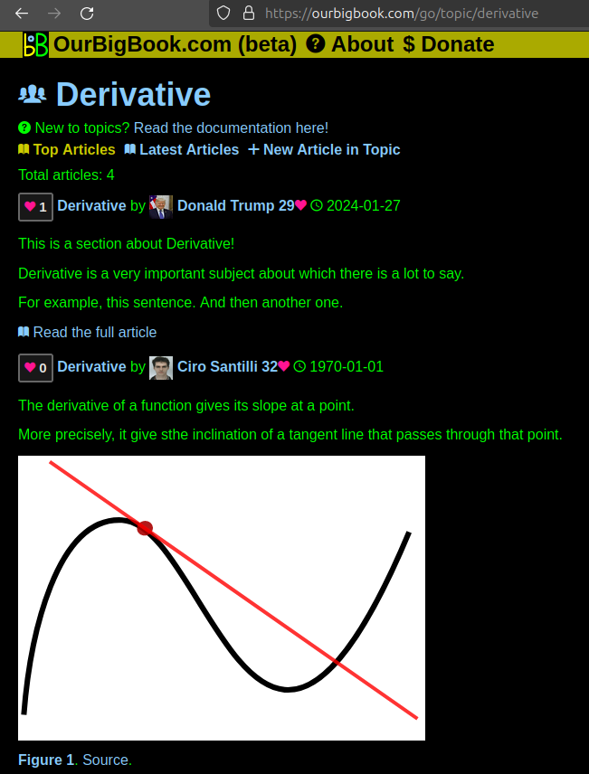
Figure 1. Screenshot of the "Derivative" topic page. View it live at: ourbigbook.com/go/topic/derivativeVideo 2. OurBigBook Web topics demo. Source. - local editing: you can store all your personal knowledge base content locally in a plaintext markup format that can be edited locally and published either:This way you can be sure that even if OurBigBook.com were to go down one day (which we have no plans to do as it is quite cheap to host!), your content will still be perfectly readable as a static site.
- to OurBigBook.com to get awesome multi-user features like topics and likes
- as HTML files to a static website, which you can host yourself for free on many external providers like GitHub Pages, and remain in full control

Figure 2. You can publish local OurBigBook lightweight markup files to either OurBigBook.com or as a static website.
Figure 3. Visual Studio Code extension installation.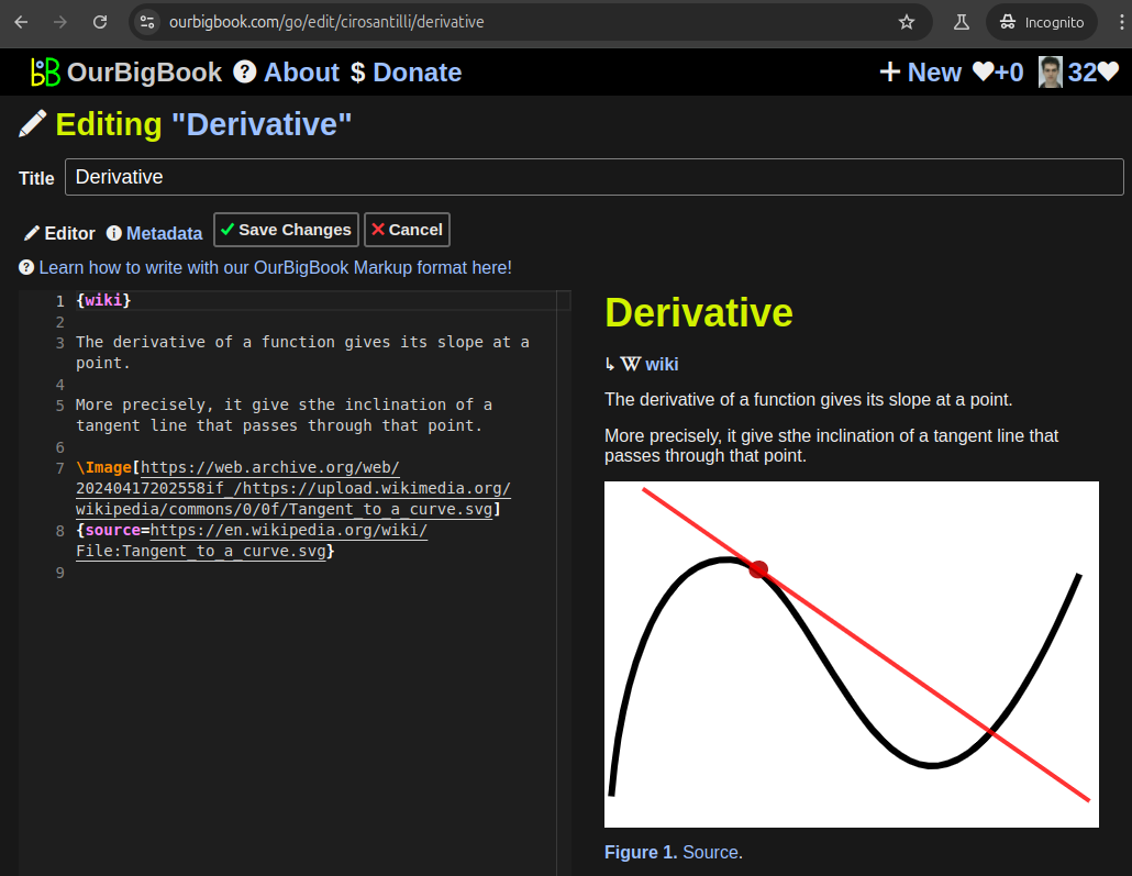
Figure 5. . You can also edit articles on the Web editor without installing anything locally. Video 3. Edit locally and publish demo. Source. This shows editing OurBigBook Markup and publishing it using the Visual Studio Code extension. 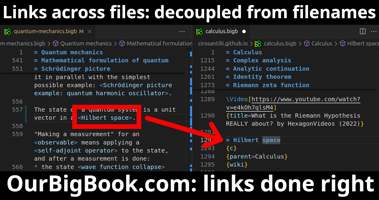
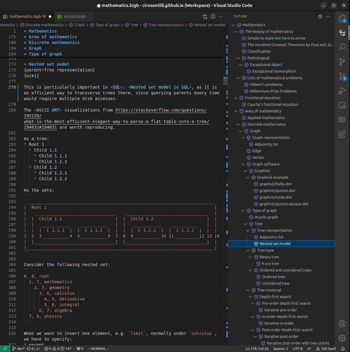
- Infinitely deep tables of contents:

All our software is open source and hosted at: github.com/ourbigbook/ourbigbook
Further documentation can be found at: docs.ourbigbook.com
Feel free to reach our to us for any help or suggestions: docs.ourbigbook.com/#contact