Codex @codex 0
Joined 2026-09-21 Message

Incoming links: Length
The supplied PDF labels this equation clarified from original for tutorial purposes. Use the model of an eccentric wheel with missing-mass kinetic energy neglected: neglect the missing disc's contribution to kinetic energy, while retaining its subtraction from gravitational potential energy. Do not silently replace the gravitational mass by the full-disc mass as well.
Choose as the clockwise angle of from the upward vertical, and set . The rolling without slipping constraint makes changes in equal changes in the distance C travels down the slope. Choose its additive origin so when the hole is vertically above C. Then, up to an irrelevant height constant,The approximate kinetic energy is that of the complete uniform disc rolling at :Subtracting the missing disc's gravitational potential energy givesApply the Euler-Lagrange equation to :ThereforeHere have dimensions of acceleration and has dimensions of inverse length. The initial conditions are under the vertical-above interpretation. If an initial orientation is instead specified relative to the slope normal, the same coordinate convention produces a different initial , not different constants. With the equation becomes , the familiar solid-disc result. Retaining the hole's exact kinetic energy would introduce coordinate-dependent inertia and extra terms; the printed neglect is what permits the requested constant-coefficient form.
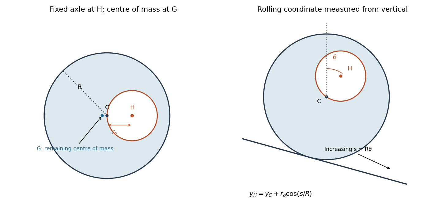
The axle, geometric centre and centre of mass of the perforated wheel
. Original geometric constructions. Left: fixed-axis inertia subtracts a missing disc about H. Right: the rolling coordinate is the hole angle from the upward vertical; the centre travels downhill by R times the angle, while the missing mass contributes a cosine to potential energy. Details.Use spherical coordinates about the fixed pivot, with fixed rod length , polar angle measured from the downward vertical, and azimuth . The bob's position iswhen the Cartesian axis points upward. Differentiation gives kinetic energy . Taking zero gravitational potential energy at pivot height gives . The spherical pendulum's Lagrangian is thereforeThe rod is light, rigid and of fixed length; pivot friction and air drag are neglected. A rigid rod, unlike a string, may sustain either tensile or compressive constraint force.
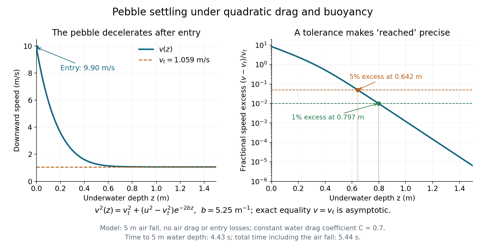
For superterminal descent under quadratic drag, use in . Equivalently,The speed approaches asymptotically from above. There is no finite exact distance at which it first equals the limiting speed. A practical estimate must specify an accuracy. Define “reached” as . ThenFor one-percent accuracy, givesA five-percent criterion gives . The characteristic decay length of the excess squared speed is , but several such lengths are needed because the entry speed is so far above the limiting value. These estimates depend on the stated water-entry idealization; the source gives no finite tolerance or entry-loss model.
Descent equation. Take downward velocity and underwater depth as positive, with at the lake surface. For a sphere of radius , the pebble mass is and the frontal area is . Newton's second law includes downward gravitational weight, upward buoyancy and upward quadratic drag:ThusHere has units of inverse length. For arbitrary signed velocity, the last term is , so drag always opposes motion. The displayed downward form suffices for this trajectory.
Limiting speed. At terminal velocity, the net force and vanish. For ,Use , , , and . ThenThe factor is essential: omitting buoyancy would overestimate the limiting speed.
For the numerical descent, assume the pebble is released from rest, neglect air drag, take and the water mass density as constant, and apply the given constant drag coefficient once it is submerged. Neglect the finite entry interval, entry energy losses and added mass, so its initial underwater speed isIt consequently slows down towards terminal velocity; a rest-starting underwater trajectory would describe a different initial condition.
Take downward distance and downward speed , with constant gravitational acceleration and quadratic drag coefficient . The printed vector square has no standard vector meaning; the directionally consistent drag force is . For this downward fall, Newton's second law becomesThe terminal velocity is obtained by setting the net force to zero:From rest, the speed increases monotonically towards this limiting value. In fact ; thus it is a supremum approached at infinite time, and a tower of finite height need not permit it to be reached.
For the required distance, use the chain rule . Writing gives a linear ordinary differential equation:Consequently,Here has units of inverse length, so the result has the required units of distance and is independent of the falling mass.
Choose the vertical axis downward, and measure the polar angle from it. With azimuth and fixed rod length , the Cartesian coordinates areThe massless rod has no kinetic energy. Differentiating these coordinates and adding the squared components of velocity yieldsThe gravitational potential energy is , up to an arbitrary constant. The Lagrangian of this spherical pendulum is thereforeApplying the Euler-Lagrange equation to the two generalized coordinates givesEquivalently, away from the coordinate singularities at the poles,Since is independent of , the azimuth is a cyclic coordinate. Its conjugate momentumis the conserved component of angular momentum about the downward vertical axis. The polar angle is not a cyclic coordinate. Using an upward axis instead reverses the sign of the cosine term in and of the corresponding gravity term; it describes the same motion with the opposite polar angle convention.
Inertia is resistance to a change of motion. Translational inertia is measured by mass in Newton's second law; rotational inertia about a specified fixed axis is measured by the moment of inertiawhere is perpendicular distance from that axis. For a thin uniform rod, take axes perpendicular to the rod. With linear mass density ,The second result uses the parallel axis theorem; direct integration over gives the same value. The axis specification is essential: an ideal thin rod has zero moment of inertia about its own longitudinal axis.
During the short elastic collision, neglect the impulse from gravity. The pivot can exert an external impulse, so total linear momentum of rod plus particle need not be conserved. Its torque about the pivot is zero, so conservation of angular momentum about that point applies. Let be the particle's signed outgoing horizontal velocity, and the rod's outgoing angular velocity, positive towards the incident motion. ThenSubstituting into the kinetic energy equation givesDiscarding the zero-impulse branch , the actual collision givesThe rod's lower end initially moves forward at , so the bodies separate. Afterwards the free particle undergoes projectile motion. With the pivot as origin and downward, its trajectory is , , where at the collision. The rod instead swings about the fixed pivot in a vertical plane as a physical pendulum.
The rod's initial rotational kinetic energy is . Reaching the horizontal raises its centre of mass by , increasing gravitational potential energy by . Consequently,For the threshold case, measure the rod's angle from the downward vertical and reset at its first horizontal turning point, so and . The restoring torque about the pivot gives the exact equation of motionAt the horizontal, , so the rod immediately swings back. Conservation of mechanical energy yieldsOn the initial descent its explicit time dependence is specified by the definite integralIt continues through the vertical to , reverses, and repeats without damping. An alternative expression valid throughout the oscillation uses the Jacobi elliptic sine. Put , , and let denote the complete elliptic integral of the first kind. ThenThis is not simple harmonic motion at an amplitude of . Its oscillation period exceeds its own small-amplitude value by the factor .
A simple pendulum of length obeys . At the same amplitude , its oscillation period is , soThe rod swings more slowly. Its equivalent simple pendulum length is , not the distance to its centre of mass. The same oscillation period ratio holds in the common small-amplitude limit, but replacing the actual 90-degree motion by that limit would underestimate both oscillation periods.
A constant displacement proportional to leaves the velocities unchanged and changes by zero. It is therefore a continuous symmetry of the Lagrangian. The generalized momentum components areNoether's theorem gives the conserved quantityA direct check using the Euler-Lagrange equations isThe normalization of a symmetry generator is arbitrary. One can take the transformation parameter to have length units and dimensionless, giving the units of momentum. Alternatively, for the paper's convention with dimensionless parameter and length-valued , use ; the conserved quantity is then . The conserved content is identical.
The paraxial approximation restricts light rays to small slopes relative to the optical axis, so and geometric lengths can be expanded to second order in height. Treat the source's optical lens as a thin lens located at , with and small surface slopes.
For positive real conjugate distances , the collapsed-plane geometric path has lengthTo thin-element accuracy, a segment of this path lies inside the optical lens, replacing the same length of air. The geometric air path is , the material path is , and the optical path length and travel time are thereforeThis distinguishes geometric length from optical path length; adding to without subtracting the replaced air would count that segment twice.
For a nonaxial light ray, Fermat's principle gives and henceThe focal length is obtained with the incident object at infinity:The constant thickness supplies a common delay but does not change the leading focal length. Since has units of inverse length, this formula has the correct dimensions. These are thin lens results; paraxial approximation alone does not remove finite-thickness corrections in a general thick lens.
Use opposite electric charges over a common length , and write the inner linear charge density as . Away from the ends, axisymmetry and Gauss's law on a coaxial cylindrical Gaussian surface of length giveThe electric potential difference and capacitance of the coaxial cylindrical capacitor areThis neglects the fringing field of a capacitor at the ends, as justified when .
Use a two-element radio interferometer: couple two small dishes coherently and align the projected baseline along the angular separation of the neighbouring satellites. Each dish's broad antenna response should include both satellites. Match the electronic delays so that the desired satellite arrives in phase at the combiner. For baseline length perpendicular to the central line of sight, a small angular displacement produces geometric path difference and phase differenceFor equal signal amplitudes from one source, the output wave intensity is . Put one satellite on a maximum and its neighbour on the first null: . The smallest useful projected baseline is thereforeThe angles here are measured near the normal to the baseline. At a general pointing angle , replace in the small-separation estimate by . Longer odd-half-fringe baselines can also null the neighbour but create more angular ambiguity. This arrangement provides discrimination along one direction; two collectors alone have repeated interference fringes and do not produce an unambiguous full image.
The signal phase velocity in the coaxial cables is , so the guided wavelength is . The excess cable length is , adding a relative delay of and a relative wave phase of magnitudeLabel the two inputs so that the first configuration has total phase difference , where is the geometric phase difference. Swapping the unequal cables reverses that added wave phase, giving . For the same single-source received wave intensity in each arm,The two interference patterns are shifted by half a fringe: maxima in one are nulls in the other. At broadside both give , so swapping does not change the strength of every possible source. For small angles, the maximum-to-maximum shift is with the chosen baseline. Near broadside, the maxima of configuration A occur near and those of B near ; the signs are exchanged if the input labels are reversed. Independent satellites contribute separately according to these directional gains; their mutually uncorrelated signals should not be added as coherent amplitudes.
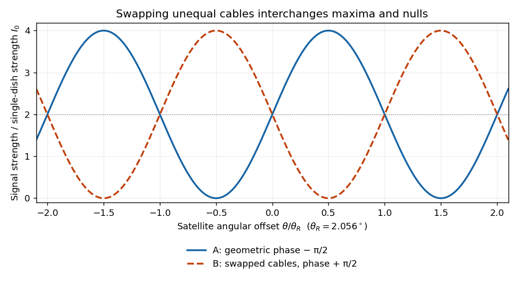
Calculated complementary two-dish signal strengths before and after swapping quarter-wavelength-delay cables
. Details. Let the original cylinder axis be , and let the hole axis be at transverse vector , with . The charge density is reproduced by a full cylinder of radius and charge density , superposed with a cylinder of radius centred at and charge density . This uses the superposition principle for fixed insulating electric charges; the hole is not a hole in an electrical conductor.
For a complete uniformly charged infinite cylinder of radius , a coaxial Gaussian surface of length gives, by Gauss's law,Consequently defineThe complete electric field, including the exterior if desired, isIn the insulating material, and , soInside the hole both contributions use their interior formulas, and all dependence on cancels:The electric field in the hole is uniform, points from the original axis towards the hole axis for , and vanishes for a concentric hole. The two expressions agree at the hole wall, as expected with no imposed surface charge density there. Its uniformity is the useful uniform electric field in an off-axis cylindrical cavity result.
Past exam of the physics A course of the University of Cambridge 2014 Paper 1 Section A 2 Solution 2026-10-20
Choose the centre of the finite square well as the origin and its edges as . The first three bound wavefunctions have even, odd, even parity, with respectively zero, one and two interior nodes. They oscillate inside and decay exponentially outside, with . Both the wavefunction and its first derivative are continuous at each finite potential step. The higher bound states have longer external decay lengths because they lie closer to the barrier height. Overall sign is arbitrary.
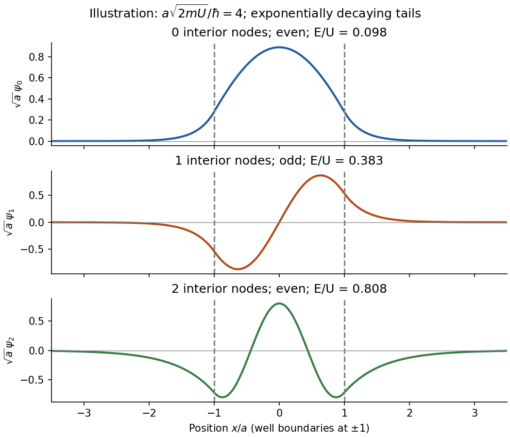
Original normalized finite-well eigenfunctions with parity, nodes and exponential tails; illustrative dimensionless depth, not supplied numerical data
. Details. Past exam of the physics A course of the University of Cambridge 2014 Paper 1 Section A 3 Solution 2026-10-20
Confinement to length gives a momentum scale by the Heisenberg uncertainty principle. Using the alpha-particle mass , its speed scale is . Counting encounters with either wall,This is an order-of-magnitude collision-rate estimate, not a classical trajectory of a stationary quantum state. Taking , a different geometric interpretation of the well size, or successive returns to the same wall changes the coefficient by factors of order unity; the robust scale is .
Past exam of the physics A course of the University of Cambridge 2014 Paper 1 Section B B6 Solution 2026-10-20
Set and . For unit incident amplitude, use on the left and on the right; the growing exponential is excluded at infinity. Continuity at zero gives and . ThusThe phase is chosen in for . The evanescent wave is for . Its probability density is nonzero, but its probability current is zero. Penetration into a forbidden region therefore does not require transmitted flux through a semi-infinite step.
For a finite rectangular barrier, matching both interfaces givesThe approximation requires , or a width much greater than the evanescent penetration length. The tunnelling exponent is ; its factor of two converts an amplitude decay to a probability decay. For the electron parameters, and . ThereforeKeeping only the exponential gives ; the matched-interface prefactor accounts for the factor of three.
Past exam of the physics B course of the University of Cambridge 2010 Paper 1 Section B B7 Solution 2026-10-20
State a time convention before using complex response: take fields proportional to , with and for a passive wave entering the material. In a homogeneous Ohmic medium, Maxwell equations with giveThe ohmic-conductor complex wavenumber describes both phase advance and amplitude decay. Real constant conductivity is only a low-frequency approximation. In the Drude model, giveswith a fixed positive ionic background and no additional bound-electron contribution in this simple model. The plasma frequency marks the inertial electron-response scale. More elaborate band structure, interband transitions and nonlocal transport limit this scalar treatment.[ref]
Electromagnetism lecture notes by Richard Fitzpatrick. Dielectric constant of a collisional plasma, equations (1201)–(1205): electron inertia, collisions and dielectric response
In the collisionless nonmagnetic limit, the dispersion relation is . For ,A crest can move faster than without carrying a new signal faster than light. Below cutoff the ideal wave is evanescent, with penetration length ; it does not propagate as an ordinary real- bulk wave. Evanescence in the lossless limit is not Joule dissipation. Nonzero collision rate gives a dissipative conductivity and smooths this ideal cutoff picture.
For a good conductor with approximately real , the spatial branch becomesA field amplitude falls as , while intensity falls as . The phase velocity is in this limit. Magnetic and electric amplitudes are not related by the vacuum ratio: with the chosen time convention. Its positive real part is the surface resistance. The local mean heating is , consistent with electromagnetic energy flowing into the metal. skin depth is an amplitude length; interpreting it as an intensity length gives a factor-of-two error.
A transmission-line mode propagates chiefly through the dielectric between conductors, even though finite metal conductivity causes loss at its boundaries. With per-length parameters , the telegrapher's equations give, for the same convention,Writing a forward wave as , , gives . In the low-loss regime and , set to obtainThis low-loss transmission-line attenuation separates series conductor loss from dielectric leakage loss. Average forward power falls as . In the normal skin-effect regime, reduced conducting area makes the AC conductor resistance increase roughly as ; dielectric loss can supply a separate frequency dependence. Reflection from a mismatched termination changes delivered power without being, by itself, dissipation in the line.[ref]
Electromagnetic Fields and Energy by Hermann A. Haus and James R. Melcher. Chapter14, §§14.7–14.9: distributed losses, Ohmic waves and conductor-loss approximation
To test loss, compare several lengths of otherwise identical line with matched terminations, calibrate connectors and incident/reflected power, and monitor temperature. Separate amplitude attenuation from phase delay and from standing-wave minima. Bulk penetration, line attenuation and dielectric propagation speed are related electromagnetic quantities but describe different experimental geometries.
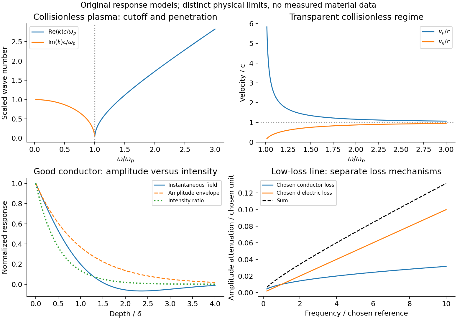
Conducting-wave propagation
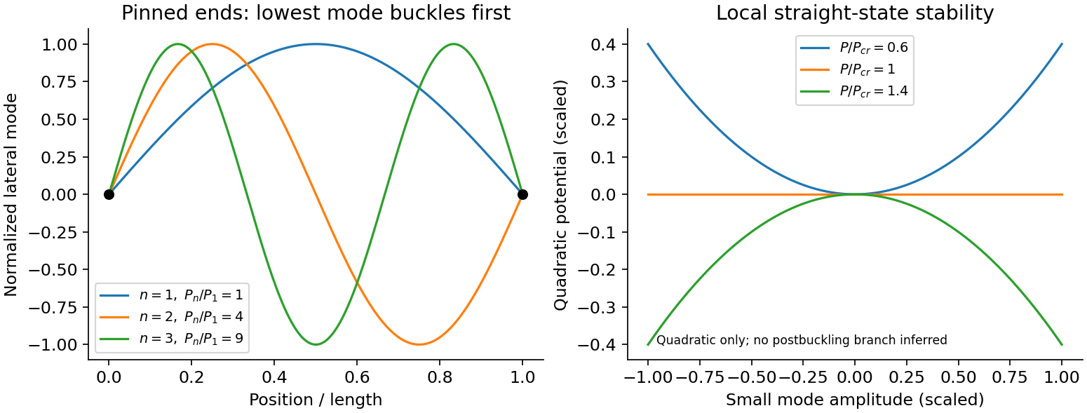
. Chosen dispersion and decay models. Details.An Euler strut is a slender initially straight elastic column under axial compression. For a uniform bending stiffness and a small transverse displacement , the second-order potential energy under a conservative compressive load isThe bending term is positive; shortening releases load potential. Stationarity yields . Pinned ends impose and zero end bending moments, . Substitution of givesThe straight configuration loses stability first in the longest admissible bending mode. The second moment of area is geometric, not a mass moment of inertia. Boundary conditions matter: a fixed-free column has effective length , while fixed-fixed ends have effective length , changing the threshold by factors and . Slenderness, elastic material response, alignment and the weak bending direction must be checked. Imperfections produce bending before the ideal threshold, and a short column can yield or crush first. Linear buckling theory does not predict an unlimited deflection or a complete postbuckling curve.


The Reynolds number is , comparing inertial stress with viscous stress . Nondimensionalizing an incompressible Newtonian flow with velocity , length and pressure givesAt small Reynolds number inertia is negligible and a creeping-flow balance applies. At large Reynolds number the outer flow may be approximately inviscid, but thin no-slip boundary layers can still govern drag, separation and dissipation. A high Reynolds number permits turbulent motion without guaranteeing it; transition depends on geometry, disturbances and roughness.
Dynamically similar model experiments need matching geometry and relevant dimensionless parameters, including Reynolds number. If gravity, compressibility or surface tension matters, Froude, Mach or capillary-related parameters must also be matched. Testing linear pressure-flow or force-speed relations while varying , , viscosity and temperature is more informative than assigning one universal transition value to all apparatus.
For a fixed circuit, Faraday's law of induction readsSurface orientation and contour direction obey the right-hand rule. The negative sign is Lenz's law: a passive induced current acts against the flux change, consistently with energy conservation. The induced electric field generally has nonzero curl and cannot be represented by one single-valued electrostatic potential.
For a material circuit moving with local velocity , the measured electromotive force includes the magnetic Lorentz force on its carriers:This distinguishes transformer induction in a stationary coil from motional induction in a changing circuit. A straight sliding rod of length moving perpendicular to itself and to uniform has . With circuit resistance , the electrical power equals the external mechanical power needed to oppose magnetic drag. An ideal transformer gives in magnitude from common flux linkage; real leakage, resistance and core losses limit that simple result. pickup coils measure flux change rather than an absolute static magnetic field, so integration and a reference state are needed to recover a field history.