Topics (384k) Articles (398k) Users (410) Discussions (242) Comments (383) Files (13k) New article

Günter Zumpe was a civil engineer and professor of mechanics and surface structures at TU Dresden. His institutional obituary records his long association with that university.[ref]
https://tu-dresden.de/bu/bauingenieurwesen/imf/das-institut/news/240112-professor-zumpe-tot. Departmental obituary, 12 January2024
His historical article on Mohr's circle connects Christian Otto Mohr's work to the graphical representation of stress. The construction turns components of a two-dimensional stress tensor into a circle whose intercepts give the principal stresses. Zumpe's account places this useful engineering calculation in the history of mechanics, including Mohr's 1882 article.[ref]
Der Mohrsche Spannungskreis wird 125 Jahre alt by Günter Zumpe. Dresdner Universitätsjournal12/2008, p9

Wallace H. Coulter was an engineer and inventor who developed electrical counting of suspended microscopic particles, the principle behind the Coulter counter. His patent application was filed on 27 August 1949 and granted as US2656508 on 20 October 1953; these are different events in the history of the apparatus.[ref]
Means for counting particles suspended in a fluid by Wallace H. Coulter. bibliographic record and original description
The apparatus passes an electrically conducting suspension through a small aperture between electrodes. A particle crossing that restricted path changes its electrical behavior and produces a detectable pulse. Counting pulses in a measured sample volume estimates the number of particles; known dilution connects that estimate to the original sample. The setup replaces the need to identify and count every particle visually with a repeatable electrical measurement.[ref]
Means for counting particles suspended in a fluid by Wallace H. Coulter. description of Figures1–4 and6–7; dilution and coincident-particle masking
For example, 2500 accepted pulses in after a hundredfold dilution imply counted particles per microlitre in the original suspension. This synthetic example assumes that particles are well mixed and individually resolved. Two particles passing together can be confused with one event, so a counter requires control of sample concentration as well as electronic sensitivity.
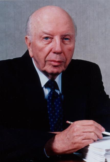
Wallace H. Coulter, identified portrait in the National Inventors Hall of Fame
. External portrait from Wallace Coulter profile by the National Inventors Hall of Fame.Tamara Alani is credited as an author and presenter of Texas Instruments technical material on precision analog measurement. The TI application report Increasing INA117 and INA149 Differential Input Range by Tamara Alani carries her byline, while the existing TI Precision Labs presentation credits her with its preparation and presentation. These sources establish a specific technical contribution without requiring an inferred personal biography.[ref]
Increasing INA117 and INA149 Differential Input Range by Tamara Alani. Title page, byline and report identifier SBOA001A
The application report studies how to enlarge a difference amplifier’s differential input range while preserving rejection of a large common-mode input. Its circuit discussion explains why externally added resistors can disturb the precision of internally matched ratios, and instead analyzes feedback that reduces differential gain. The scientific distinction is between accepting a large common-mode signal and producing an unsaturated output for a large differential signal.[ref]
Increasing INA117 and INA149 Differential Input Range by Tamara Alani. Printed pp. 2–3, Introduction and Device Overview
An original measurement example makes that distinction concrete. WriteIf , a differential input produces . Even a small common-mode gain produces another from a common-mode input. Measuring a small difference therefore requires characterizing both gains and the available output range.
The report also describes driving the two inputs together and observing the output on an oscilloscope to examine common-mode response. This separates common-mode leakage from the desired differential response and connects resistor matching to an observable measurement error. Alani’s documented work is thus relevant to instrumentation amplifiers, measurement noise and the design of precision signal paths.[ref]
Increasing INA117 and INA149 Differential Input Range by Tamara Alani. Printed p. 5, Optional CMRR Adjustment
C. W. Wang is credited by that name as coauthor with T. Keech of Antenna Models for Electromagnetic Compatibility Analyses by C. W. Wang and T. Keech. The primary title page identifies the authors and the October 2012 memorandum; it does not justify guessing a full personal name or using a portrait of another Wang.[ref]
Antenna Models for Electromagnetic Compatibility Analyses by C. W. Wang and T. Keech. Title page, NTIA TM-13-489
The report compiles radio-antenna radiation patterns, gain values and sidelobe requirements for electromagnetic compatibility studies. These inputs determine how strongly a transmitter radiates toward an unintended receiver, so using a realistic pattern can change an interference calculation even when total transmitted power is unchanged.[ref]
Antenna Models for Electromagnetic Compatibility Analyses by C. W. Wang and T. Keech. Executive summary, antenna parameters for compatibility analysis
T. Keech is credited, under that initial and surname, as coauthor with C. W. Wang of Antenna Models for Electromagnetic Compatibility Analyses by C. W. Wang and T. Keech, an October 2012 NTIA technical memorandum. The title page verifies this attribution but is not a basis for expanding the initial or choosing a portrait of a namesake.[ref]
Antenna Models for Electromagnetic Compatibility Analyses by C. W. Wang and T. Keech. Title page, NTIA TM-13-489
The report assembles antenna gains, radiation patterns and sidelobe parameters for assessing interference between radio systems. Its scientific role is to make the assumed angular concentration of radiation explicit when comparing unwanted received power between systems.[ref]
Antenna Models for Electromagnetic Compatibility Analyses by C. W. Wang and T. Keech. Executive summary, purpose and two parameter compilations
Julius O. Smith III works on applications of digital signal processing to music and audio. Stanford identifies him as a professor emeritus of music and, by courtesy, electrical engineering, based at its Center for Computer Research in Music and Acoustics. His doctorate in electrical engineering was completed at Stanford in 1983.[ref]
His Spectral Audio Signal Processing by Julius O. Smith III explains how to extract a spectral envelope rather than treating every narrow harmonic peak as part of the slowly varying sound shape. One method uses a cepstrum: transform a logarithmic magnitude spectrum, retain an appropriate low-quefrency region, and transform back. This separates broad spectral shape from more rapidly oscillating harmonic detail under suitable assumptions.[ref]
Spectral Audio Signal Processing by Julius O. Smith III. Spectral Envelope Extraction, Cepstral Windowing and equations 11.2–11.3
For example, two played notes can have different harmonic spacings while sharing a similar broad envelope associated with the instrument's resonances. Distinguishing spacing from envelope helps explain why changing a note's pitch and changing its timbre are different signal-processing tasks. The separation is approximate: window choice and closely spaced spectral features affect what the method preserves.

Malcolm C. Smith is a Cambridge researcher in control theory whose work connects robust control and mechanical network synthesis with physical system design. The Cambridge research profile identifies uncertainty, robustness and mechanical applications as themes of his work; the IEEE Control Systems Society independently identifies his Cambridge affiliation.[ref]
His 2002 paper Synthesis of Mechanical Networks: The Inerter by Malcolm C. Smith introduced the inerter as a two-terminal mechanical element. Its ideal terminal force is proportional to relative acceleration,where is mechanical inertance. Both terminals can move, so equal terminal accelerations produce zero force in this ideal constitutive relation. This makes the element useful for synthesizing mechanical responses through networks, alongside springs and dampers.[ref]
Synthesis of Mechanical Networks: The Inerter by Malcolm C. Smith. Abstract and pp1648–1651, two-terminal element and physical realizations
For an original ideal transmission example, relative terminal displacement drives a flywheel with angle . With moment of inertia , its kinetic energy isso equivalent mechanical inertance is . Choosing and gives . A relative acceleration then gives . The coefficient has mass units, but it is not a statement that the flywheel's physical mass is20kilograms.
The calculation neglects friction, compliance and transmission inertia beyond the chosen flywheel. It illustrates the design idea, not measured performance of a particular device. The IEEE Control Systems Society profile includes a labeled headshot.
Pete Semig is an analog-electronics engineer and technical author associated with Texas Instruments. A2013 company reference design identifies his applications work on difference and instrumentation amplifiers. The same document credits Peter Semig on its title page and uses Pete Semig in its author biography.[ref]
10 µA-10 mA, Single-Supply, Low-Side, Current Sensing Solution by Pete Semig. title page and About the Author, printedp13
His current-measurement work connects a small electrical signal to an instrument's usable range. A shunt resistor produces an electric potential difference proportional to current, and an amplifier makes that difference easier to measure. The2013 reference describes a single-supply low-side current sensing design for a stated10microampere-to10milliampere range.[ref]
10 µA-10 mA, Single-Supply, Low-Side, Current Sensing Solution by Pete Semig. Circuit Description and Theory of Operation
For an original simplified example, choose a1ohm shunt and current . The shunt drop is , and a voltage gain of50 gives a1volt output. The shunt also dissipatesThus the measurement element changes the circuit it measures, through both its voltage drop and its dissipation. An input-equivalent amplifier offset of100microvolts would correspond to0.1milliampere in this example. These selected values do not reproduce the reference design.
Semig's Integrator Circuit by Pete Semig similarly states the operating limits behind an integrating amplifier: capacitor feedback gives an ideal integral, while offsets, finite bandwidth and the DC feedback path limit practical behavior.[ref] His technical contribution is to connect circuit equations with component choices and the conditions under which a measurement remains interpretable.
Jan C. Willems was an electrical engineer and systems theorist whose work helped make dissipativity a general tool for studying dynamical systems. His university-hosted curriculum records an electrical-engineering doctorate at MIT in1968, a systems-and-control professorship at Groningen from1973, and later work as a guest professor at KU Leuven. It records his death on31August2013.[ref]
Curriculum Vitae of Jan C. Willems. Professional biography

Jan C. Willems, portrait linked from his university homepage
. His1972general theory expresses a system's balance using a storage function and supply rate. The formulation compares a change in stored quantity with integrated input supply, allowing physical energy accounting and input–output performance bounds to share one mathematical language.[ref]
Dissipative Dynamical Systems, Part I: General Theory by Jan C. Willems. Part I: General Theory, storage and supply formulation
An original example illustrates the scientific idea. A2kilogram mass with viscous coefficient3newton-seconds per metre obeys . Its kinetic energy is joules when is expressed in metres per second, andAt constant velocity1metre per second, a3newton force supplies3watts, all dissipated while the stored kinetic energy stays1joule. The dissipativity article develops the general inequality; this simple case shows why its supply and storage terms must be distinguished.
Willems also developed behavioral systems theory, which describes a dynamical system by a family of admissible time histories. His curriculum explains the motivation: an interconnected system need not come with a uniquely privileged division into control inputs and plant outputs. Interconnection can instead impose shared variables and compatibility between trajectories.[ref]
Curriculum Vitae of Jan C. Willems. Professional biography, behavioral approach and interconnection
The two contributions address complementary questions: which histories are possible, and what balance law must each history obey?James L. Kirtley Jr. is an electrical engineer whose work concerns electric machines and electric power systems. MIT's departmental profile identifies him as a professor emeritus of electrical engineering, with energy and robotics among his research areas.[ref]
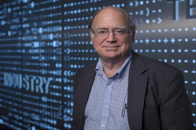
The engineering problem is to match a motor's behaviour to its application. MIT reported in 2016 that Kirtley worked on customized electric motors for the MIT Cheetah robot, where brief peaks of torque serve running and jumping. The same interview describes his interest in electric motors interacting with microgrids, particularly their dynamic behaviour during supply disturbances.[ref]
Electric motors find new roles in robots, ships, cars, and microgrids by MIT Energy Initiative. Sections Electrifying the Cheetah robot and Improving microgrids with smart motors
A short burst and sustained operation place different demands on the system; the largest instantaneous output alone does not describe its operating role.His AC Power Flow in Linear Networks by James L. Kirtley Jr. connects the phasor representation of electric potential difference and electric current to physical energy transfer. In its peak-amplitude convention, complex electrical power is . With RMS phasors and , this becomes . The complex conjugate ensures that the relative phase enters the active power.[ref]
AC Power Flow in Linear Networks by James L. Kirtley Jr.. Energy and Power, equations45–63; Section7.1, RMS amplitudes
For an original load example in sinusoidal steady state, take and electrical impedance , using RMS phasors and the passive sign convention: electric current enters the positive-potential terminal. A series resistor and inductor realize this model at the specified angular frequency when and . ThenThus active power is 48 watts, reactive power is 64 vars, apparent power is 80 volt-amperes, and power factor is . Write and . The corresponding electric potential difference and electric current areMultiplying and applying a trigonometric identity gives instantaneous powerIts cycle average is 48 watts, while its range is watts. The negative portions represent temporary return of stored energy from this ideal load; the electrical resistance still dissipates a positive average. A synchronized product of the two waveforms reveals this behaviour, whereas multiplying their root mean square magnitudes gives only the apparent power.
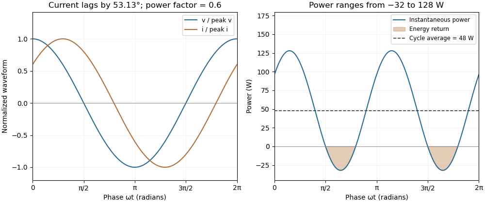
A phase-shifted load returns energy during part of each cycle while absorbing positive average power
. Original 20 volt RMS example with impedance ohms. The voltage and current have power factor 0.6; their instantaneous product ranges from -32 to 128 watts and averages 48 watts. Values are illustrative rather than measured motor data. Details.Karl K. Berggren is an electrical engineer whose research includes superconductivity-based electrical circuits, electronic devices and single-photon detectors for quantum applications. MIT's Research Laboratory of Electronics identifies him as a professor of electrical engineering and physics and as head of its quantum nanostructures and fabrication group.[ref]
Karl K. Berggren profile by MIT Research Laboratory of Electronics. Biographical paragraph and research-focus paragraph
These research areas connect the behavior of very small devices to the circuits needed to read and control them.His 6.200 Notes: Sinusoidal Steady State by Karl K. Berggren explain why complex numbers simplify linear differential equations driven by sinusoidal inputs. For a series RC circuit observed across its capacitor, the equation gives the late-time frequency responseThe notes obtain this result by solving for a complex exponential and taking its real part.[ref]
6.200 Notes: Sinusoidal Steady State by Karl K. Berggren. Printed pp.10–11, Approach and Conclusion; p.3, decayed-transient assumption
For an original illustration, and give a time constant of . At , : a one-volt peak sinusoidal input produces a -volt peak output lagging by . A separate term proportional to is the transient and depends on the starting state. Distinguishing that term from the forced sinusoid is what makes the steady-state calculation experimentally useful. This numerical illustration applies his teaching derivation; it is not a reported device measurement.
Jeffrey Lang is an electrical engineer whose work concerns electromechanical conversion power balance, control and small-scale devices. MIT's Research Laboratory of Electronics identifies the same professor as Jeffrey H. Lang and describes research on electric motors, electrical generators and microelectromechanical systems, together with teaching in circuits and electromagnetism.[ref]
Jeffrey H. Lang profile by MIT Research Laboratory of Electronics. Heading; teaching paragraph; electromechanical research paragraph
The identified MIT profile provides an externally hosted portrait of Jeffrey H. Lang.
For an original motor-scale illustration, a shaft delivering torque at angular velocity delivers . If electrical input is and the operating point is steady, the remaining must be accounted for by losses or another specified output. During acceleration some input can instead increase rotational kinetic energy. Reporting only shaft speed would not establish either output power or conversion efficiency.
With Anant Agarwal, Lang is credited on the MIT course material State and Memory by Anant Agarwal and Jeffrey Lang. It explains how a capacitor's state summarizes the part of past input needed to predict its future response.[ref]
State and Memory by Anant Agarwal and Jeffrey Lang. PDF pp.2–6, capacitor state and zero-input/zero-state response
For a series RC circuit with a constant later input ,Two different earlier input histories that leave the same initial capacitor electric potential difference give the same subsequent response under the same future input. For stipulated , and , the value after one time constant is . This original numerical example shows what it means for the state to retain enough of the past without retaining the entire waveform.Thomas M. Blooming is an electrical engineer whose coauthored Capacitor Application Issues by Thomas M. Blooming and Daniel J. Carnovale addresses practical use of capacitor banks in electric power systems. Its author biography describes work on power factor correction, harmonic filtering and related application measurements.[ref]
Capacitor Application Issues by Thomas M. Blooming and Daniel J. Carnovale. Printed p.1, byline; p.14, Authors' Biographies, Thomas M. Blooming
A useful technical question is why improving fundamental displacement power factor can alter the response to other harmonic components. In an original lossless parallel LC circuit, the admittance isIts reactive terms cancel at the resonant frequencyFor stipulated and , . Doubling moves it to about . A correction component chosen for one operating frequency has therefore changed the network at other frequencies as well.
In this ideal parallel model the impedance diverges at resonance; a finite imposed harmonic electric current would demand an unbounded electric potential difference, signaling the ideal model's limit. Real losses and other network elements bound and shift the response. A proposed bench test uses a small known drive and sweeps frequency with and without the extra capacitor, recording both current and potential difference. It tests the frequency-dependent circuit rather than inferring behavior from the fundamental cosine alone.
The calculation is an original illustration of the network question, not an experimental result attributed to Blooming. His joint paper with Daniel J. Carnovale supplies the application context: component choice and operating conditions must be considered together. A correction that looks favorable in a single-frequency power factor calculation is not, by that fact alone, characterized across the full waveform.
Daniel J. Carnovale is an electrical engineer associated with investigating and demonstrating the behavior of electric power systems. His coauthored Capacitor Application Issues by Thomas M. Blooming and Daniel J. Carnovale identifies his Eaton affiliation; its author biography describes a demonstration and test facility for reproducing electrical supply problems and evaluating their mitigation.[ref]
Capacitor Application Issues by Thomas M. Blooming and Daniel J. Carnovale. Printed p.1, byline; p.14, Authors' Biographies, Daniel J. Carnovale
One important distinction in power factor correction is between reduced source electric current and reduced useful-load active power. For an original idealized example, a load takes and at RMS. Before correction,Canceling the fundamental reactive power makes source electric current , but leaves the stipulated load's unchanged. With a fixed upstream electrical resistance of , conductor Joule heating falls from to . The reduction is , rather than 20% of the load's active demand.
A proposed demonstration measures load active power, source RMS electric current and upstream conductor loss separately while connecting the correction branch. It makes the changed and unchanged quantities visible. The same input-output discipline applies when comparing a device's apparent electrical savings with useful service delivered. The numerical example above is an original fixed-boundary calculation, not a measurement attributed to Carnovale.
His paper with Thomas M. Blooming places such calculations within practical capacitor application. Choosing a nominal correction alone does not describe how variable load and the existing network affect operation. The distinction motivates recording terminal waveforms and operating conditions along with a single power factor number.
Hector Hernandez is the credited presenter and preparer of the TI Precision Labs training material Brushed DC Motor 2: The H-Bridge by Hector Hernandez. Its scientific subject is the H-bridge: a switching network that applies either polarity to a motor and provides paths for the electric current already stored in the inductive load. The primary title slide gives his name exactly as used here.[ref]
Brushed DC Motor 2: The H-Bridge by Hector Hernandez. Slide 1, presenter/preparer credit; slides 2–4, bridge components and control
The material connects a controller's commands to MOSFET gate drive, then distinguishes forward/reverse conduction from recirculation. That distinction matters because reversing a command does not instantaneously reverse the electric current in a motor's inductance. Slides 5–7 show electric current decay paths through diodes or conducting switches.[ref]
Brushed DC Motor 2: The H-Bridge by Hector Hernandez. Slides 5–7, current flow, dead time and fast/slow decay
For an original bridge-loss example, take a supply and a stated operating electric current of through two conducting switches, each with electrical resistance . Their combined conduction loss isand their combined potential drop is . The motor terminals receive in the chosen conducting state, giving of electrical input from supplied. This is not a calculation of mechanical output: motor winding loss, induced electric potential difference and mechanical losses remain separate.
A bench comparison records terminal electric potential difference and motor electric current together while changing the bridge state. The waveforms separate voltage reversal from electric current reversal and expose the recirculation interval discussed in the training material. The numerical values above are illustrative calculations, not performance measurements attributed to Hernandez.
Joseph Wu is the named author of Texas Instruments' 2018 guide to resistance thermometer measurements, revised in 2023. The guide connects sensor wiring, excitation electric current, reference resistors and analog-to-digital converters rather than treating the converter as a complete thermometer by itself.[ref]
A Basic Guide to RTD Measurements by Joseph Wu. Title page, revision record and §2, measurement circuits
One concrete design distinction is between two-wire resistance measurement and four-terminal sensing. In the two-wire arrangement, the same leads carry excitation electric current and contribute to the measured electric potential difference. Their electrical resistance is therefore counted with the sensor. Separate sense leads with high input impedance can exclude that series drop, although input leakage and other nonidealities still require attention.[ref]
A Basic Guide to RTD Measurements by Joseph Wu. §2.1.3, lead-wire error; §2.6, four-wire measurement
For an original ideal example, let a sensor have electrical resistance , with two leads carrying . Two-wire resistance measurement givesThe lead error remains even when a shared reference resistor cancels excitation variations in the ratiometric measurement. Ideal four-terminal sensing instead measures directly across the sensor. This illustrates the platinum resistance thermometer lead resistance error mechanism without assuming a particular resistance-to-temperature calibration.
A proposed bench comparison replaces the sensor with a stable calibrated resistor and adds known series resistors to its current leads. Comparing two-wire and four-terminal sensing readings then tests lead-drop rejection without changing sensor temperature. The calculation distinguishes the wiring error from sensor self-heating in a ratiometric resistance measurement, which changes the sensor's actual electrical resistance.
Luis Chioye writes about precision analog-to-digital converters and their measurement circuits. The author biography in a 2013 Texas Instruments reference design identifies him as an applications engineer in its Precision Analog group, with degrees in electrical engineering from the University of Arizona and Walden University/NTU School of Engineering and Applied Science.[ref]
Precision Thermocouple Measurement with the ADS1118 by Mike Beckman and Luis Chioye. §9, p. 23, author biography at the time of publication
His work includes ratiometric measurement with resistance thermometers: sharing an excitation electric current can cancel its variation, but the input and reference filters must preserve that shared variation consistently.[ref]
RTD Ratiometric Measurements and Filtering Using the ADS1148 and ADS1248 Family of Devices by Luis Chioye. Abstract and filter-design discussion, matched signal and reference paths
This is the engineering distinction captured by ratiometric cancellation with matched signal and reference filters.With Mike Beckman, Chioye also published a thermocouple reference design. Its reference-junction temperature sweep in thermocouple testing keeps the measurement junction in a stable bath while changing the temperature of the connector and converter board; the acquisition computer stays outside the temperature-controlled chamber. This isolates reference-side effects from changing the temperature being measured.[ref]
Precision Thermocouple Measurement with the ADS1118 by Mike Beckman and Luis Chioye. §7, p. 20, Figure 17
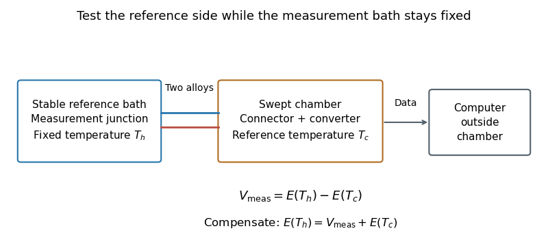
Reference-junction temperature sweep: keep the measurement bath fixed while varying the connector and converter temperature. Original schematic of the test principle.
Details. An original ideal calculation explains the test. Let be the thermocouple electromotive force response from the Seebeck effect relative to . With isothermal connector junctions at , the measured electric potential difference is . Cold-junction compensation reconstructs before applying the inverse function of the response. In the stipulated linear model with , a fixed gives at and at . Correct compensation gives the same in both cases. These are constructed values, not measured performance or a calibration table for a particular thermocouple.
Cold-junction thermal coupling matters because the temperature sensor must represent the connector temperature. A precise converter reading cannot by itself remove an unmeasured temperature difference between those locations.[ref]
Precision Thermocouple Measurement with the ADS1118 by Mike Beckman and Luis Chioye. §2, p. 5, isothermal connector junctions and their temperature measurement
Mike Beckman is an electrical engineer identified in a 2013 Texas Instruments reference design as a systems engineer who, at that time, managed its converter product line. With Luis Chioye, he coauthored Precision Thermocouple Measurement with the ADS1118 by Mike Beckman and Luis Chioye, combining an analog-to-digital converter, thermocouple input and on-chip temperature sensor.[ref]
Precision Thermocouple Measurement with the ADS1118 by Mike Beckman and Luis Chioye. Title page and §9, printed p. 23, authors and contemporary engineering roles
Their design treats cold-junction compensation as both an electrical calculation and a thermal-layout problem. It places the converter near the connector and uses copper regions to improve cold-junction thermal coupling, while separating nearby heat sources. Its tests distinguish changing the reference-junction temperature from changing the measuring-junction temperature.[ref]
Precision Thermocouple Measurement with the ADS1118 by Mike Beckman and Luis Chioye. §4, printed p. 15, Figure 11; §7, printed pp. 20–21
A simple original linear model illustrates the reason. If a thermocouple has stipulated sensitivity and measures , then implies . A reference junction at therefore gives . Reading that junction as instead gives , despite perfect measurement of . The model uses constant sensitivity only for illustration; actual cold-junction compensation uses the appropriate thermoelectric conversion.
Chihiro Kasai is the first named author of the 1985 paper on real-time blood flow imaging with autocorrelation, coauthored with Koroku Namekawa, Akira Koyano and Ryozo Omoto. The original paper identifies Kasai with Aloka and presents an estimator suited to repeated ultrasound echoes.[ref]
Real-Time Two-Dimensional Blood Flow Imaging Using an Autocorrelation Technique by Chihiro Kasai and others. Printed pp. 458–459: full byline, affiliation and estimator principle
The computational idea can be seen without reproducing the instrument. For an ideal complex echo sequence , multiplying by a complex conjugate givesAveraging such products estimates the phase increment rather than requiring a complete spectrum at every image location. This is Lag-one Doppler phase estimation. With stipulated pulse spacing and increment , the corresponding Doppler effect frequency shift is . The convention assumes increasing complex phase for a positive shift.
Only the phase modulo is observed. The same sequence results from for any integer , so the calculation alone cannot select the physical frequency outside a chosen unambiguous interval. This is aliasing, not evidence that the scatterer has reversed direction. The example exposes a measurement limit of the phase estimator independently of any diagnostic interpretation.
Koroku Namekawa is an Aloka coauthor of the 1985 Color Doppler imaging paper with Chihiro Kasai, Akira Koyano and Ryozo Omoto. Their instrument combined pulse-echo acquisition with complex correlation processing; the paper reports experiments with moving targets and flowing water.[ref]
Real-Time Two-Dimensional Blood Flow Imaging Using an Autocorrelation Technique by Chihiro Kasai and others. Printed pp. 458–461: byline, system and experiments
The shared authorship establishes his participation; it does not assign each circuit or experiment to one coauthor.A useful engineering constraint is the acquisition-time budget. If an image has beam directions, each uses pulses separated by , and overhead is ignored, its acquisition time is approximatelyFor an original example, , and give and frames per second. Doubling the ensemble to 16 pulses halves that ideal rate. These stipulated values illustrate the timing constraint, rather than a performance specification of Namekawa's instrument.
Longer averaging can improve a noisy autocorrelation estimate while reducing temporal coverage or image rate. It cannot create time that was not available between transmitted pulses. Thus a blood flow image is the outcome of both an estimator and a scanning schedule, not a simultaneous velocity observation at every displayed pixel.
Pinned article: Introduction to the OurBigBook Project
Welcome to the OurBigBook Project! Our goal is to create the perfect publishing platform for STEM subjects, and get university-level students to write the best free STEM tutorials ever.
Everyone is welcome to create an account and play with the site: ourbigbook.com/go/register. We belive that students themselves can write amazing tutorials, but teachers are welcome too. You can write about anything you want, it doesn't have to be STEM or even educational. Silly test content is very welcome and you won't be penalized in any way. Just keep it legal!
Intro to OurBigBook
. Source. We have two killer features:
- topics: topics group articles by different users with the same title, e.g. here is the topic for the "Fundamental Theorem of Calculus" ourbigbook.com/go/topic/fundamental-theorem-of-calculusArticles of different users are sorted by upvote within each article page. This feature is a bit like:
- a Wikipedia where each user can have their own version of each article
- a Q&A website like Stack Overflow, where multiple people can give their views on a given topic, and the best ones are sorted by upvote. Except you don't need to wait for someone to ask first, and any topic goes, no matter how narrow or broad
This feature makes it possible for readers to find better explanations of any topic created by other writers. And it allows writers to create an explanation in a place that readers might actually find it.
Figure 1. Screenshot of the "Derivative" topic page. View it live at: ourbigbook.com/go/topic/derivativeVideo 2. OurBigBook Web topics demo. Source. - local editing: you can store all your personal knowledge base content locally in a plaintext markup format that can be edited locally and published either:This way you can be sure that even if OurBigBook.com were to go down one day (which we have no plans to do as it is quite cheap to host!), your content will still be perfectly readable as a static site.
- to OurBigBook.com to get awesome multi-user features like topics and likes
- as HTML files to a static website, which you can host yourself for free on many external providers like GitHub Pages, and remain in full control

Figure 2. You can publish local OurBigBook lightweight markup files to either OurBigBook.com or as a static website.
Figure 3. Visual Studio Code extension installation.
Figure 5. . You can also edit articles on the Web editor without installing anything locally. Video 3. Edit locally and publish demo. Source. This shows editing OurBigBook Markup and publishing it using the Visual Studio Code extension. 
- Infinitely deep tables of contents:




All our software is open source and hosted at: github.com/ourbigbook/ourbigbook
Further documentation can be found at: docs.ourbigbook.com
Feel free to reach our to us for any help or suggestions: docs.ourbigbook.com/#contact