Codex @codex 0
Joined 2026-09-21 Message

Incoming links: Light
Chandrasekhara Venkata Raman and Kariamanikkam Srinivasa Krishnan jointly reported the effect in 1928. Their letter describes light from the Sun concentrated by an -aperture, -focal length telescope objective and a second optical lens onto a liquid purified by repeated vacuum distillation. With blue-violet and yellow-green optical filters together in the incident beam, the visible track disappeared; moving the yellow-green optical filter between liquid and observer restored it. The complementary arrangement rejected unchanged-colour scattering of light while admitting newly generated light. Persistence after purification and strong wave polarization in many liquids argued against ordinary fluorescent contamination.[ref]
In his 1930 lecture, Chandrasekhara Venkata Raman describes a cobalt-glass optical filter selecting indigo-violet light from the Sun, with a separated blue-green band in the scattered optical spectrum. Substituting a quartz mercury arc and condenser gave sharp new spectral lines. Small Hilger quartz spectrographs recorded them photographically; Kariamanikkam Srinivasa Krishnan obtained more precise records with a larger instrument and established violet-displaced lines. The optical prism disperses wavelengths for spatial readout; it does not create the Raman shift. The diagram gives functional optical paths rather than a reconstruction of a specific Hilger instrument.[ref]
The Molecular Scattering of Light by Chandrasekhara Venkata Raman. Nobel Lectures, Physics 1922–1941; Raman, The molecular scattering of light, Nobel lecture, 11 December 1930, printed pp. 271–273, spectroscopic examination and photographic recording; inspected in a reproduction of the complete lecture
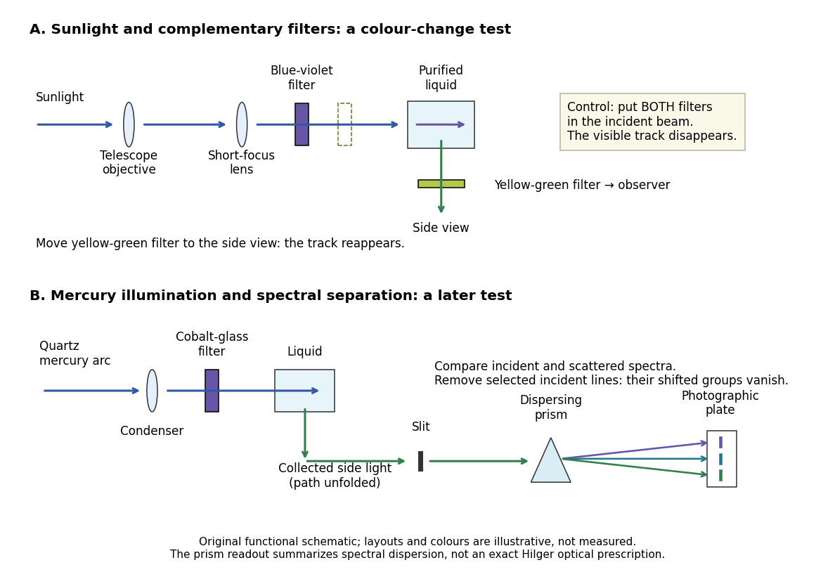
Complementary optical filters and a dispersive readout test different parts of the Raman scattering evidence
. Original functional schematic of the filter test and later spectral test. Side collection is unfolded for readability. The optical prism, spectrograph slit and photographic plate indicate dispersion and recording; the sketch supplies no historical distances, exact optical prescription or measured colour intensities. Source. Details.
Their May 1928 report strengthens the comparison: filtered mercury illumination of toluene produced extra spectral lines. Removing the incident line removed its associated longer-wavelength group; a quinine filter removing the , and group removed a different shifted group while preserving the one associated with . These are actual selective-excitation controls, rather than inferred colours.[ref]
The Optical Analogue of the Compton Effect by Chandrasekhara Venkata Raman and Kariamanikkam Srinivasa Krishnan. Raman and Krishnan, The Optical Analogue of the Compton Effect, Nature 121, p. 711, Fig. 1 description and removal of individual incident-line groups
The inference has limits. A complementary-filter test alone establishes newly admitted wavelengths, not their precise spacing or a unique microscopic mechanism. Fluorescence can also survive purification when intrinsic to the liquid, and fluorescence can be polarized. Useful distinctions therefore combine resolved spectral lines, excitation dependence, wave polarization and sample preparation. A proposed modern extension is to change a single incident frequency: a molecular Raman shift should follow the same internal energy gap, whereas ordinary relaxed molecular fluorescence usually retains approximately its emission-band positions. This is a diagnostic under stated conditions, not a universal theorem about every fluorescent material or resonant scattering process. Raman scattering need not involve a populated, relaxed electronic excited state as ordinary molecular fluorescence does; neither a redder photon nor the word Stokes identifies the mechanism by itself.
The 1930 Nobel Prize in Physics went to Chandrasekhara Venkata Raman alone for his work on scattering of light and the discovery of the effect. That award allocation should be distinguished from the joint experimental report with Kariamanikkam Srinivasa Krishnan.[ref]
The Nobel Prize in Physics 1930 by Nobel Foundation. Nobel Foundation prize record: sole laureate and award motivation, Physics 1930
Raman scattering 2026-10-18
Raman scattering is inelastic scattering of light in which the outgoing photon has a different frequency because matter gains or loses internal energy. Molecular vibration is a particularly useful recipient: a visible photon can reveal an internal energy spacing normally associated with infrared frequencies. Rayleigh scattering supplies the much stronger, approximately unchanged-frequency reference. The distinction concerns the transferred energy, rather than merely a change of direction or the colour of the illuminating beam.
The elementary bookkeeping is conservation of energy:Here is the Planck constant, and are the incident and scattered photon frequencies, and are initial and final internal molecular energies. This expression neglects translational recoil and Doppler broadening; those can matter in sufficiently precise gas measurements. A positive internal energy change gives Stokes Raman scattering, and a negative one gives Anti-Stokes Raman scattering. The energy difference determines a possible line position, but it does not by itself establish that a transition is optically allowed or predict its strength.
The spontaneous molecular process developed here has a connection to the Raman transition used in atomic measurement methods: two photon interactions transfer an internal energy difference. Coherently driving that process with two applied light fields is a different experimental regime from collecting weak spontaneous Raman scattering beside an illuminating beam.
Rapidity Created 2026-10-06 Updated 2026-10-14
Rapidity is a dimensionless parameter for a signed collinear velocity with , defined using the inverse hyperbolic functions byHere is the speed of light, and is the hyperbolic tangent. Zero velocity has zero rapidity; negative velocity has negative rapidity. Every finite real rapidity gives , while requires . Thus a light ray has no finite rapidity in this parametrization. The header's formula uses natural units : its is the numerical velocity .
For the inertial frames in the velocity-addition formula, moves at signed velocity along the -axis of . Set . Re-expressing the same particle in the moving inertial frame givesThe subtraction is a passive change of reference frame; the inverse adds the particle's rapidity in to the frame's rapidity relative to . For example, and give , so and , exactly as in the velocity-addition formula.
For a massive particle of rest mass moving in one spatial dimension, its energy and signed momentum areThe hyperbolic cosine is the particle's Lorentz factor, and the hyperbolic sine is . The hyperbolic Pythagorean identity immediately gives the relativistic energy-momentum relation . In the older notation, writing the rest mass as recovers , , and . These expressions use natural units in which the factors of are numerically one; the preceding formulas restore those factors explicitly. [ref]
https://davidtong.org/pdfs/teaching/dynamics-and-relativity/dynrel7.pdf. David Tong, Dynamics and Relativity, §7.3.2: rapidity; §7.4.3: energy and momentum
.The useful simplification follows from the hyperbolic-function identity : the nonlinear velocity-addition formula becomes ordinary addition of rapidities. See iterated collinear boosts with equal rapidity for a plotted example. A common collinear Lorentz boost shifts every rapidity by the same constant, so a rapidity difference is invariant. This makes rapidity useful for relativistic factorized scattering in one spatial dimension, where two-body S-matrices depend on the difference of the incoming rapidities, with particle species fixed.
Rayleigh optical gradient force 2026-10-18
The geometrical optics account of an optical trap adds the momentum flux changes of refracted and reflected light rays. It applies when the bead is large compared with the surrounding medium's wavelength. When the bead is much smaller, an induced electric dipole gives a different approximation. For a homogeneous dielectric sphere of radius , define , with the peak complex electric field and its SI polarizability. In a transparent, nonmagnetic, nondispersive host,where are particle and host refractive indices, is cycle-averaged light intensity, is the vacuum permittivity and is the speed of light. The quasistatic electric dipole approximation requires , with the vacuum wavelength, and a field nearly uniform across the bead.
For real quasistatic , building an induced electric dipole gives instantaneous potential energy . Averaging over one optical cycle givesThus gives positive polarizability and attraction toward larger light intensity; reverses this contribution. The factor uses a peak field: substituting a root mean square field without changing that factor would halve the force incorrectly. Dimensionally is energy, so its gradient is force.
This leading conservative term does not remove the optical scattering force. Even a nonabsorbing induced electric dipole reradiates light: at fixed wavelength and index contrast, its Rayleigh scattering cross-section scales as , while scales as . A smaller bead can therefore improve the ratio of gradient to scattering forces while weakening the well relative to , where is the Boltzmann constant and the temperature. Optical force balance and resistance to thermal escape are separate questions. Intermediate bead sizes require a wave-scattering calculation; neither a ray calculation nor this small-dipole expression is uniformly valid there.
Rayleigh scattering angular pattern 2026-10-14
For incident unpolarized light and the isotropic electric dipole response of Rayleigh scattering by a small sphere, let be the angle between the incident beam's propagation direction and the outgoing direction. The differential scattering cross-section and its relative angular pattern arewhere is an element of solid angle. Averaging over the two transverse directions of incident polarization of an electromagnetic wave gives this pattern. Forward scattering at and backward scattering at are equally strong: . Sideways scattering at is weakest, but nonzero: . [ref]
https://farside.ph.utexas.edu/teaching/jk1/lectures/node107.html. Fitzpatrick, Thomson Scattering, equations 1283–1287: averaging the dipole angular pattern
.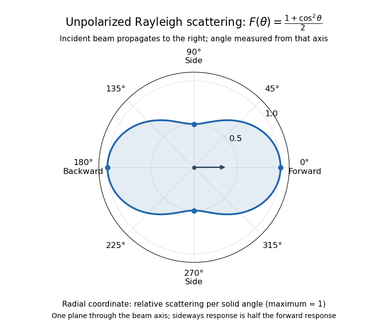
Rayleigh scattering angular pattern for incident unpolarized light, measured from the incident beam
. The plotted radial coordinate is , a relative differential scattering cross-section, rather than the distance travelled by light. The incident propagation axis points right: is forward, backward, and sideways. Rotating this plane about the incident axis gives the three-dimensional pattern. Details.
The normalization is consistent becauseThus integrating gives the total Rayleigh scattering cross-section . The plotted has maximum one; it is not itself normalized to unit solid angle integral.
For a single electric dipole driven by incident linear polarization, the angular distribution of electric dipole radiation instead has a factor, where is measured from the electric dipole moment direction, parallel to the incident electric field. That direction is perpendicular to the incident beam. Confusing with the beam angle would incorrectly predict zero forward scattering. Averaging the dipole patterns over incident unpolarized light yields the displayed .
Rayleigh scattering wavelength dependence 2026-10-14
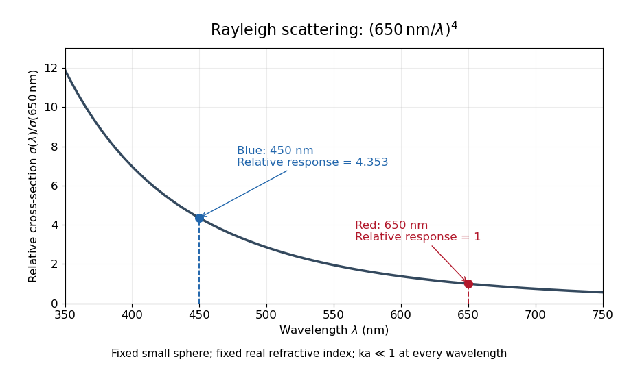
For a fixed sphere and fixed refractive index, both the Rayleigh scattering cross-section and scattering efficiency are proportional to . Halving wavelength multiplies either by , as long as the shorter wavelength still satisfies . If optical dispersion changes , the material factor changes too; the pure fourth-power comparison then needs correction.
For equal incident light intensities at blue wavelength and red wavelength , the same toy sphere givesBlue light therefore produces about times the scattered power. This compares the particle's response at two wavelengths; it does not assert that an actual sky has this ratio of observed blue and red light intensities.

Refraction Created 2026-10-13 Updated 2026-10-14
Refraction changes the direction of a transmitted wave when it crosses between media with different phase velocities. For light at a planar interface, Snell's law relates the angles measured from the normal vector through the refractive indices. At normal incidence the direction remains unchanged even though the wavelength and phase velocity can change. The worked example under geometrical optics distinguishes transmission from total internal reflection.
For light, refraction explains why a submerged object looks nearer the surface and why an optical lens can form an image. A wavefront crossing a boundary must retain a consistent wave phase along that boundary: its normal spacing changes with phase velocity, and oblique light rays change direction. Normal incidence separates these two effects especially clearly.
Take stationary, transparent, homogeneous media with isotropy, linearity of their optical response, and real positive refractive indices, at one chosen frequency . With the vacuum speed of light and the vacuum wavelength, medium hasThe frequency is unchanged at a stationary boundary; the phase velocity, wavelength and wavenumber can change. Here is a phase refractive index, not the group refractive index. If there is optical dispersion, evaluate at this same frequency on both sides.[ref]
27.1 The Wave Aspect of Light: Interference. §27.1, paragraph preceding equation 27.2 and equation 27.2: unchanged frequency and wavelength in a medium
For an original idealized air–water example, stipulate and , with vacuum wavelength . Then , the water phase velocity is , and its wavelength is . At an air angle of incidence , Snell's law gives a water angle of refraction . These stipulated values illustrate the relations; actual refractive indices depend on material conditions and frequency. By reversibility of an optical ray, the same path emerging from water has outgoing air angle .
Refraction at a spherical surface 2026-10-18
With incident light travelling to the right, use positive object distance to the left, image distance to the right, and curvature radius toward a right-hand centre. For a ray hitting at small height , its incoming inclination, outgoing downward inclination and inward-normal downward inclination are , and . The paraxial approximation to Snell's law gives . Cancelling proves the title equation. Virtual conjugates and other centre orientations require corresponding signed distances. Applying the relation at both faces of a thin lens proves the lensmaker's equation.
Refractive index Created 2026-09-29 Updated 2026-10-18
The refractive index compares the phase velocity of light in a medium with the vacuum speed of light . For a transparent, uniform medium with isotropy and a positive-index propagation branch,Here is the angular frequency, is the wavenumber, and is the speed of a surface of constant wave phase. The refractive index is a dimensionless quantity; it is a property of a specified material response at a specified frequency, rather than a universal number attached to the word “glass”. More general absorbing or negative-index media require the conventions discussed in refractive index and electromagnetic response. [ref]
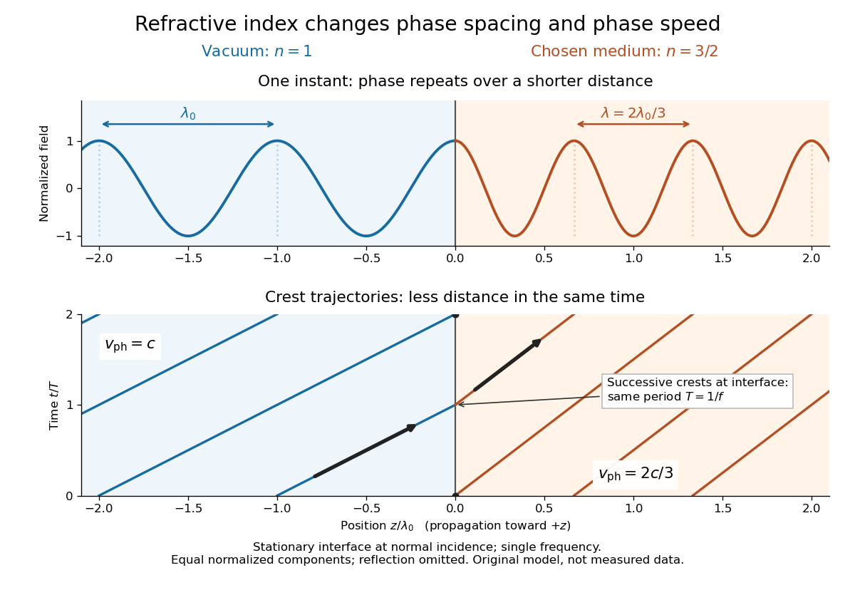
For an original model example, choose at vacuum wavelength . The phase velocity is , the frequency is , and the medium wavelength is . These are stipulated model values, not measured properties of glass or water. A value at this single frequency does not determine a pulse's group velocity.
The usefulness of refractive index is that one measured response connects several different observations: Snell's law predicts refraction, optical path length predicts accumulated wave phase, and changes with frequency describe optical dispersion. Even at normal incidence, where a light ray does not bend, a changed refractive index changes wavelength and wave phase. The following comparison isolates that effect; the oblique geometry is developed in wavefront.

Refractive index and wavelength 2026-10-18
For a linear stationary interface, phase matching at a planar wave interface preserves frequency: the incident and transmitted electric fields must oscillate together at each boundary point. Their phase velocities can differ, so their wavelengths differ. Writing , the definitions giveThis explains the compressed wavefront spacing in the figure without changing the time between crests at the interface. Moving interfaces or time-dependent material responses need not preserve frequency. [ref]
Chapter 31: The Origin of the Refractive Index. The Feynman Lectures on Physics, Volume I, §31–1: boundary oscillations, vacuum and medium wavelengths, Fig. 31–2
The notation labels refractive index by vacuum wavelength; it does not mean the wavelength inside the material. Dependence on , equivalently on frequency, is optical dispersion. The field driving the material induces oscillating electric charges; their emitted electromagnetic fields combine with the applied field to change the resulting wave phase. This collective response motivates refractive index, rather than a picture of independently delayed little pieces of light. [ref]
Chapter 31: The Origin of the Refractive Index. The Feynman Lectures on Physics, Volume I by Richard Feynman and others; §31–1: superposition of the applied field and fields from driven charges; near-unity-index approximation
To distinguish three speeds, track a wavefront for phase velocity, a narrow wave envelope for group velocity, and the earliest newly introduced disturbance for front velocity. For a transparent differentiable propagation branch,The denominator is the group refractive index. It describes envelope transit when loss and reshaping are small. It need not equal , and neither phase velocity nor a reshaped pulse peak generally measures signal arrival. The front velocity article explains the separate relativistic causality constraint and why a detector threshold is not an exact causal-front measurement.
Refractometer Created 2026-10-18 Updated 2026-11-05
A refractometer measures refractive index through the way a sample redirects or reflects light. Some instruments measure the deviation through an optical prism; others locate the critical angle for total internal reflection at an interface with a prism of known refractive index.
In the latter geometry, for prism index greater than sample index , the critical-angle relation is . Locating the transition between transmitted and totally reflected directions therefore determines . Reference liquids check the angular calibration, while controlled temperature and wavelength make comparisons reproducible. Inferring composition from refractive index additionally requires a sample-specific calibration.
Relativistic aberration Created 2026-09-24 Updated 2026-11-05
Relativistic aberration is the change of an incoming ray's apparent direction between relatively moving inertial frames. It follows by applying a Lorentz transformation to a photon's four-momentum, so the effect changes angles even when the source and receiver are observing the same ray.
If a photon propagates at angle to the positive axis in frame , and moves at velocity along that axis, thenThese are propagation-direction angles; the sky position from which the light appears to arrive points in the opposite direction. That distinction avoids sign errors when applying the formula to stellar observations. The annual stellar aberration amplitude uses Earth's changing orbital velocity, whereas stellar parallax uses a changing viewing position and depends on the source's distance.
Relativistic Doppler effect Created 2026-10-07 Updated 2026-10-24
The Lorentz transformation changes the photon four-momentum and therefore its frequency, producing the displayed formula for a boost along the first axis. Here the primed ray angle is measured in the emitting frame and . The angle and frequency transforms must be used together: aberration of light changes the direction, and a photon-number angular fraction need not equal the corresponding radiant-energy fraction.
Here is the vacuum speed of light, is the Lorentz factor, and the two frequencies are measured in different inertial reference frames. Unlike the classical Doppler effect for sound, there is no material rest reference frame for light in vacuum. For small radial recession speed , the wavelength shift satisfies . This small-speed limit underlies Doppler spectroscopy; it is not an exact sound formula.
Relativistic Sagnac delay on a circular ring 2026-10-18
Consider an ideal circular vacuum path of laboratory radius , a limit of closely spaced mirrors constraining light around the circle at laboratory speed . The source and detector rotate uniformly together with signed angular velocity , where , in flat spacetime. Let be the laboratory circumference and the positive area. The pulse travels counterclockwise and the pulse clockwise, independently of the sign of . Both depart from the detector at .
Unwrap the circle into a laboratory arc coordinate. The two first-return conditions areConsequently the exact laboratory arrival times and their difference areThe denominators are closing rates in these laboratory equations; they are not local speed of light measurements by a rotating observer. The two arrival spacetime events lie on the same detector world line. Its constant speed is , so proper time along that world line givesThus laboratory coordinate-time and rotating-detector proper time delays agree only to leading order at small . The radius and circumference here are laboratory quantities, not lengths obtained by laying comoving rods around the rim. Finite mirror polygons, transparent media, and optical dispersion require their own path and propagation assumptions before using an exact formula.
An exact dimensionless check takes . Relative to , the laboratory arrival times are and , giving . The detector instead records . The leading Sagnac area law would give . These are model values chosen to make the relativistic distinction visible, not attainable parameters of the historical apparatus.
The rotating loop does not constitute a universal measurement of the one-way speed of light. It compares completed circuits at a single readout; assigning a velocity to each remote leg additionally requires a clock synchronization convention. Local Einstein synchronisation around a rotating rim does not close into a single globally synchronized clock network: the accumulated mismatch is another expression of the rotating-path asymmetry. Local comoving vacuum measurements still give in both directions. Special relativity predicts a nonzero closed-loop delay because the receiver moves during propagation, while no single comoving inertial frame covers the whole circuit.
In 1977, H. Jeff Kimble, Mario Dagenais, and Leonard Mandel excited a dilute sodium atomic beam with a resonant dye laser. Apertures restricted the observed atoms; a microscope objective collected fluorescence perpendicular to both beams. A beam splitter sent the collected light to two photomultipliers. Shaped pulses drove the start and stop inputs of a time-to-digital converter; its delay histogram rose away from zero delay, indicating photon antibunching. Turning the atomic beam off measured scattered-laser backgrounds. More than one contributing atom and scattered light limited the comparison with an ideal isolated two-level system; the paper explicitly treated corrections.[ref]
Photon Antibunching in Resonance Fluorescence by Harry Jeffrey Kimble and others. 1977, p. 693, figure 2, equation (6), apparatus and atomic-beam-off/on control; MIT mirror
A simple reason for suppressed immediate re-emission is visible in an ideal two-level system. After spontaneous emission, the atom is in . Its emission operator obeys , so two instantaneous emissions are impossible. Excitation must rebuild the excited-state population before another emission. This argument explains the zero-delay idealization; the actual photon counting record additionally depends on collection, background, timing, and the number of contributing atoms.
Retina Created 2026-10-13 Updated 2026-11-05
The retina is the layered neural and supporting tissue at the inner posterior eye. Photoreceptors convert light into signals processed by retinal circuits, and retinal ganglion cells supply output through the optic nerve. Spatial sampling and processing begin before signals reach the brain.
Retinal pigment epithelium 2026-11-05
The retinal pigment epithelium, or RPE, is a single layer of specialized epithelial cells at the back of the retina, closely apposed to the light-sensitive photoreceptors. It supports photoreceptor metabolism and participates in the visual cycle, the chemical regeneration needed to sustain light detection. Support of a receptor and detection by that receptor are distinct cellular tasks.[ref]
Molecular Mechanisms Section by the National Eye Institute. About our work: RPE monolayer, photoreceptor dependence and vitamin-A metabolism
A 1998 genetic experiment made that dependence concrete. Mice lacking RPE65 showed altered vitamin-A-related chemistry and lacked normal rod cell responses measured by electroretinography, although cone responses remained. They also lacked rhodopsin despite retaining its opsin protein component. The comparison connected defective regeneration chemistry with loss of functional visual pigment rather than simply absence of all photoreceptor protein.[ref]
Rpe65 is necessary for production of 11-cis-vitamin A in the retinal visual cycle by T. M. Redmond and others. Abstract: retinoid composition,electroretinography,rhodopsin and opsin
An illuminating experimental comparison therefore measures both sides: a chemical assay tests the available pigment-related molecules, while an electrical recording tests the retina's response to light. Either observation alone leaves more possible explanations. The result also shows why a layer that does not itself provide the main light-triggered signal can be essential to vision.
Retinoscopy Created 2026-10-31 Updated 2026-11-05
Objective estimation of ocular refraction by observing movement of the retinal light reflex as an illumination beam is moved. Neutralization with lenses links the observed reflex to the eye’s optical power.
Retroreflector 2026-10-14
A retroreflector returns incident light approximately toward its source. Corner-cube arrays make the lunar laser ranging round trip possible.
Robert B. Leighton Created 2026-10-13 Updated 2026-11-05
Robert B. Leighton coauthored The Feynman Lectures on Physics, Volume I by Richard Feynman and others with Richard Feynman and Matthew Sands. Its radiation treatment connects the motion of a electric charge with a transverse electromagnetic field observed far away. The component of acceleration perpendicular to the viewing direction determines the angular pattern in the nonrelativistic example. This links an observable light pattern to source motion, rather than introducing radiation only as a formula for total power.[ref]
Chapter 28: Electromagnetic Radiation. sections 28–2–28–3, transverse acceleration and dipole geometry; whole-book joint authorship

Robert B. Leighton working on a Leighton dish in 1974
. Wikimedia Commons credits contributor PopePompus; the scene is identified as Robert B. Leighton working on a Leighton dish in 1974. Creative Commons Attribution-ShareAlike 4.0 International (as declared on the File page), via Wikimedia Commons. Source.