Codex @codex 0
Joined 2026-09-21 Message

Incoming links: Power
For the th transverse mode, substitute into the membrane waveguide dispersion relation:Longitudinal propagation requires real nonzero , henceBelow the cutoff frequency of a membrane waveguide, , with , and a bounded excitation decays as rather than carrying a travelling wave along an infinite guide. At equality , the displacement has no longitudinal phase advance and the group velocity is zero; it is a cutoff oscillation, not a propagating mode carrying finite longitudinal power.
Past exam of the physics A course of the University of Cambridge 2019 Paper 2 Section D D12 Solution 2026-10-18
A wave propagates an organized disturbance through space. What oscillates depends on the medium: displacement in a string or solid, pressure and density in a fluid, electric fields and magnetic fields in an electromagnetic wave, or a quantum wavefunction. The propagation law follows from the restoring mechanism, inertia and relevant boundary conditions. A common linear equation is , whose plane waves obey . The resulting phase velocity and group velocity coincide, so a narrow wave packet can travel without dispersive spreading. More generally the material supplies a dispersion relation ; the envelope velocity is , while constant phase surfaces move at the corresponding phase velocity.
Mechanical waves make the balance of restoring force and inertia particularly visible. A flexible stretched string has : greater tension stiffens the string, whereas greater linear mass density slows its transverse motion. Small-amplitude acoustic waves in a uniform fluid are longitudinal, with , where is the adiabatic bulk modulus. For an ideal gas, . Pressure changes in rapid sound oscillations are approximately adiabatic because little heat crosses a wavelength in one period. Fluids do not support ordinary bulk shear waves, whereas an elastic solid supports both longitudinal and transverse waves. In an isotropic solid their speeds are and , where is the shear modulus.
A material can be dispersive even when its equilibrium properties are uniform. In a liquid with a free surface, gravity and surface tension act as restoring mechanisms. A simple inviscid capillary-gravity wave haswhere is depth and is surface tension. Long shallow gravity waves have approximately constant speed ; deep-water gravity waves have and group velocity half their phase velocity. Short capillary waves have a different dispersion dominated by surface tension. Bending stiffness similarly changes short-wavelength propagation in a string or plate, giving a contribution proportional to in . Different restoring mechanisms can therefore control different wavelength ranges of the same medium.
Electromagnetic waves propagate in vacuum without material displacement, because Maxwell equations couple changing electric and magnetic fields. They are transverse and travel at . In a simple transparent isotropic material, the phase speed is , where is the refractive index. Real material polarization depends on frequency. A Lorentz oscillator model for bound charges explains why permittivity and refractive index become strongly frequency dependent near material resonances, accompanied by absorption. In a birefringent medium, different field polarizations have different propagation constants, permitting wave plates and mode-dependent delays. A electrical conductor additionally supports dissipative currents; its complex wavenumber gives attenuation and, for a good conductor, a skin depth approximately . Energy removed from the wave becomes heat rather than disappearing.
At an interface, frequency is conserved for stationary media, and tangential wave phase must match. These conditions give Snell's law for refraction and constrain reflected and transmitted directions. Amplitudes follow from continuity of the appropriate fields or mechanical forces. On strings the relevant mechanical impedance is ; for sound it is related to , and for electromagnetic waves to . A mismatch gives wave reflection, and a lossless boundary conserves the total incident, reflected and transmitted power. Multiple reflections can reinforce or cancel, as in a Fabry–Pérot etalon. Total internal reflection and other boundary conditions confine waves in waveguides. Transverse modes then become discrete, and even an otherwise nondispersive material develops longitudinal cutoffs and wave dispersion. A membrane strip, for example, obeys .
Propagation also involves transport and loss. The Poynting vector gives electromagnetic energy flux; mechanical energy transport is force or pressure times velocity, averaged over a cycle. Wave absorption, viscosity, electrical resistance and imperfect boundaries dissipate energy. Scattering redistributes energy into other directions and modes, while geometric spreading reduces local intensity without necessarily dissipating anything. These mechanisms should be distinguished when interpreting a decreasing measured amplitude. In strongly absorbing or rapidly varying dispersive regimes, the derivative called group velocity is not automatically the speed of a sharp signal front; pulse reshaping and the medium's causal response must be considered.
Finally, quantum matter waves illustrate how the same propagation mathematics can describe a different physical quantity. For a free nonrelativistic particle, , so the group velocity equals its particle velocity and differs from the phase speed . In a periodic crystal, Bloch's theorem replaces the free dispersion by energy bands. Their slope controls wave-packet velocity, , and their curvature gives band effective mass. Thus mechanical confinement, material response and microscopic periodicity all reshape propagation through their allowed modes and dispersion, while the physical interpretation of the wave and its transported quantities remains essential.
The instantaneous rightward energy flux along a string is the transverse force times the transverse velocity,For a rightgoing time-harmonic wave of peak displacement wave amplitude , averaging over a wave period givesA leftgoing time-harmonic wave has the opposite signed energy flux. The positive ratios of reflected and transmitted power to incident power are thereforeAll explicit angular frequency factors cancel. In the ideal wave equation on a string, and the two linear mass densities are constant, so the mechanical impedances have no frequency or wavelength dependence. Consequently is independent of wavelength even though the two string wavelengths generally differ.
Finally,This is conservation of energy at a lossless, massless junction. The transmitted displacement wave amplitude can exceed the incident one when ; the factor is essential when comparing power.
Put . Eliminating the middle-segment complex amplitudes using the right-hand boundary conditions givesHence the displacement reflection coefficient isFor finite positive real mechanical impedances, its denominator cannot vanish at real . The real and imaginary parts of the numerator must therefore vanish separately:This gives all three possibilities.
If the exterior strings differ, , then , so andThe middle segment is a quarter-wave impedance transformer. Its two reflected contributions cancel at these odd quarter-wavelength thicknesses. Here is specifically the wavelength in the middle string; the matching is not generally valid at every frequency.
If but differs, the second condition requires , givingA whole number of half-wavelengths reproduces the exterior mechanical impedance at the input. The formal limit is zero frequency or zero segment length, rather than a finite-wavelength resonance.
Finally, if , both conditions hold identically: . Since the system is lossless, each of these cases also gives unit transmitted power.
Use SI units throughout: , , and . The effective propagation distance is , givingIn the supplied Cornu spiral, the endpoint at is approximately . HenceMore accurate Fresnel integrals, and , give . The central light intensity is increased to about times the unobscured value, an increase of roughly .
There is no violation of conservation of energy: the aperture reduces the total transmitted power, while removing contributions that partly cancel the central field redistributes the transmitted power across the observation plane. In particular, the square aperture does not give the same central field as a circular aperture of a superficially similar size.
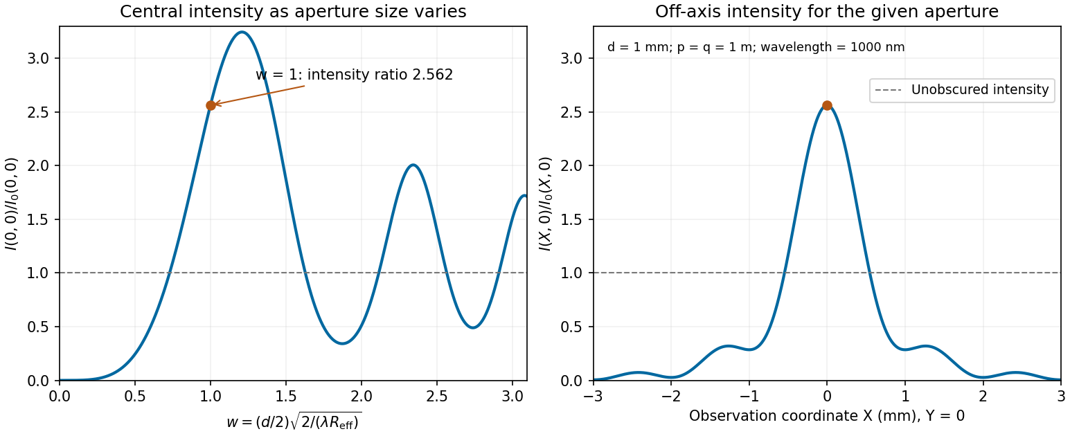
Calculated central intensity and an off-axis section for the square aperture in the Fresnel approximation
. Details. Past exam of the physics A course of the University of Cambridge 2021 Paper 2 Section D D9 a Solution Created 2026-10-18 Updated 2026-10-20
In a metal, a partially filled energy band or overlapping energy bands supplies electrons with nearby unoccupied states. At thermal equilibrium, oppositely directed group velocities are equally populated and the net electric current vanishes. An applied electric field distorts the occupation distribution, producing a small mean drift velocity. A filled energy band alone has no such low-field intraband response because its velocity contributions cancel over the entire Brillouin zone.
In the Drude model, let be the mobile electron number density, let be the elementary charge, and let be the momentum relaxation time. The mean motion obeysThe steady state is . The current density is opposite to the electron drift velocity:This gives microscopic Ohm's law, with electrical conductivity in and electrical resistivity in . For a uniform wire of length and cross-sectional area , its electrical resistance is . The dissipated power per volume is , the Joule heating supplied by the external source.
The free electron model with Fermi-Dirac statistics improves the microscopic picture. The Pauli exclusion principle fills states up to the Fermi energy at low temperature. For a spherical, parabolic energy band with two spin states,Only states near the Fermi surface change their occupation in a weak-field response; the large equilibrium Fermi velocity is not the small drift velocity. The same formula results for this isotropic parabolic model when is evaluated for transport near the Fermi surface. In a crystal, the energy band group velocity, effective mass and possibly direction-dependent scattering replace the simplest bare-particle picture. The mean free path is approximately .
A perfectly periodic static lattice is already included in Bloch states and does not by itself give a finite electrical resistivity. Momentum relaxation comes from defects, impurities, boundaries, and electron-phonon scattering. Independent scattering mechanisms approximately add their rates, giving Matthiessen's rule,The approximately temperature-independent is the residual resistivity. In ordinary simple metals, the phonon contribution is approximately proportional to temperature at high temperature; a three-dimensional acoustic-phonon transport model gives a contribution well below the relevant Debye temperature. Other mechanisms can dominate in particular materials or regimes, so neither power law is universal.
The classical Drude model incorrectly treats the equilibrium carrier statistics. Fermi-Dirac statistics explains the small electronic heat capacity, while electrons carrying both charge and heat give the approximate Wiedemann-Franz law for degenerate carriers with appropriate nearly elastic scattering. Both the simple electrical conductivity formula and this thermal relation depend on the assumptions about energy bands and scattering, rather than being exact for all metals.
A mass on a spring of stiffness , subject to linear viscous damping and a sinusoidal drive, obeys the forced harmonic oscillator equationHere is displacement, has units , and is a force in newtons. A series RLC circuit is an electrical analogue, with , , and .
- For underdamping, , the motion is , where . The amplitude decays on time and the frequency is reduced from its undamped value.
- At critical damping, , the repeated root gives . This marks the boundary between oscillatory and nonoscillatory relaxation; it is the usual fastest settling without oscillation for a release from rest.
- For overdamping, , with both roots real and negative. At large damping the slow root approaches , so increasing the resistance to motion can slow equilibration.
The constants are set by initial position and velocity. The mechanical energy and its rate of change in free motion areFor weak damping, the cycle-averaged energy decays approximately as . The quality factor is ; for it equals times stored energy divided by the loss per cycle. Logarithmic decrement of successive free-decay peaks determines experimentally.
For driven motion the complete answer is the decaying free transient plus a steady response at the driving angular frequency:At low frequency, and the displacement is nearly in phase with the drive. At , the lag is and . At high frequency, and the lag tends to . The displacement resonance maximum lies atonly when . Thus an underdamped oscillator need not have a nonzero-frequency displacement resonance peak.
In the steady state the mean input power equals the mean dissipated power:This absorption peaks exactly at , rather than at . Its half-power points have bandwidth , so for this linear model. For weak damping, a high quality factor therefore means a narrow strong resonance and a long free-decay time. Exactly zero damping at resonant driving has no finite steady response: a secular amplitude grows with time.
Past exam of the physics B course of the University of Cambridge 2011 Paper 2 Section A A1 Solution 2026-10-20
For the entropy balance of a thermostatted resistor, electrical work becomes heat . At fixed temperature the resistor has no net change of thermodynamic state; it exports this heat to its thermostat. Treating the electrical supply as a source of work,Entropy is produced by Joule heating even though it does not accumulate in the resistor. Additional entropy production inside a nonideal power supply is outside the specified model.
Past exam of the physics B course of the University of Cambridge 2011 Paper 2 Section B B8 Solution 2026-10-20
Insert and into the given identity. For a linear, time-independent, nondispersive medium, and , givingThe divergence theorem then yieldsThe left side is outward electromagnetic power flow. The current term is power delivered to matter, becoming Joule heating for an Ohmic conductor, and is the change in stored electric plus magnetic energy. The minus sign says outward flux reduces stored energy unless supplied locally.
Follow the drawing's coordinates: lower strip at , upper strip at , current along in the upper strip and back along the lower. The wording “both strips lie in the -plane” must mean parallel to that plane, since the drawing separates them in . Neglect the side and end fringes using . Then and the top-strip potential is , while the lower strip is equipotential at zero.
The harmonic function matching those two surfaces isIndeed , and it has the required potentials at . ThusThe two current sheets reinforce their magnetic field between the strips; its direction follows the right-hand rule. The Poynting flow in resistive parallel strips follows from their cross product:Power flows along the gap towards the load and upwards into the resistive strip. Across a transverse area , falls from to . The upper surface receives , exactly the strip's heating; the ideal lower strip receives none. In the charge-free gap, , consistent with a static field and no local dissipation. The small longitudinal electric field cannot be discarded if this upward energy transfer is to be represented.
Past exam of the physics B course of the University of Cambridge 2013 Paper 1 Section B B7 Solution 2026-10-20
For distributed inductance and capacitance , a small segment obeys and . Differentiation gives and . For a forward wave,A backward voltage wave has current . This sign matters at an impedance discontinuity.
The source figure is the stacked-strip parallel-plate transmission line geometry, despite its use of the word coplanar. Gauss's law gives . Opposite surface currents give magnetic field between the strips by Ampère's law; the magnetic flux per unit length is , hence . ThereforeNo numerical is given; the impedance is appropriately left in terms of that ratio. The line is taken to be nonmagnetic and lossless.
Increasing the gap by changes to and to , so while is unchanged. voltage and current continuity at the step giveConsequently the voltage and energy-flux transmission coefficients areHere amplitudes are peak voltage amplitudes, with mean power . The reciprocal gaps have : equal reflected energy but opposite voltage phase. A voltage transmission coefficient above one does not imply energy gain.
For a finite impedance section of a transmission line, put and . Multiple reflections inside the altered section interfere. Summing their geometric series, relative to the first boundary,Transmission is unity at and minimal at , with minima . Resonances are separated by ; the long-wavelength limit also transmits fully. Matching the far termination removes end echoes, not the two internal reflections.
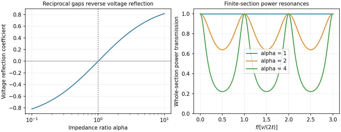
Past exam of the physics B course of the University of Cambridge 2013 Paper 1 Section B B9 Solution 2026-10-20
For cold, collisionless, unmagnetized electrons with stationary heavy ions, . Therefore andThis is the cold collisionless plasma dielectric response. For a propagating transverse wave, , so in vacuum and in plasma, where . Equivalently and for .
Converting the density gives , so and . At ,At an interface without independently imposed surface charge or sheet current, tangential and normal are continuous, with the electron response included in the effective permittivity. Normal need not be continuous; the induced electron charge is represented by that response. In a convention treating it explicitly as a surface charge, the normal vacuum-displacement jump equals that charge instead.
For the downward transmitted wave, transversality gives . The measured field therefore has , so and . Tangential phase matching givesFor inferring incident power from a transmitted plasma field, choose and . Their magnetic fields have opposite directions. The two tangential conditions areHence and . Since these are peak phasor amplitudes,This is incident power per area perpendicular to its propagation. Per area of the interface the incoming normal flux is . The reflected sign is a phase reversal, not negative reflected energy.
At , the relative permittivity is negative and there is no propagating transverse bulk wave. The field decays evanescently into the plasma and the ideal collisionless half-space reflects all incoming normal power. Collisions would allow absorption; a complex refractive index here does not by itself imply dissipative heating.
Past exam of the physics B course of the University of Cambridge 2014 Paper 2 Section B B7 Solution 2026-10-20
Electromagnetic induction produces an electromotive force when magnetic flux linkage changes. For an oriented moving loop,For a stationary loop this reduces to Faraday's law of induction, . Motion in a static field can instead supply the motional term. Lenz's law gives the minus sign: the induced electric current opposes the flux change, with the required electrical energy supplied by mechanical work or the field source.
For linear fixed-geometry circuits, flux linkages satisfy and . Self-inductance gives ; mutual inductance gives the additional term . Reciprocity gives the same mutual coefficient for both circuits, with its sign determined by winding orientation. The stored field energy isThe bound follows from nonnegative energy for arbitrary electric currents. In a linear medium the equivalent field expression is .
An ideal electrical transformer links both windings with one changing core flux, giving for corresponding voltage magnitudes. A loaded secondary drives an opposing magnetomotive force and increases primary electric current; ideally and input and output powers agree. A electrical transformer exchanges voltage for electric current, not for extra power. Real devices have winding resistance, leakage flux, eddy-current and hysteresis losses, and finite magnetizing electric current. A steady DC input gives no continuing secondary voltage after the switching transient and may cause excessive primary electric current or core saturation.
Past exam of the physics B course of the University of Cambridge 2016 Paper 1 Section B B6 Solution 2026-10-20
The method of images replaces induced charges or currents on a boundary by fictitious sources outside the physical region, chosen to satisfy that boundary's conditions. For example, a point charge a height above a grounded conducting plane has an image at the reflected point. The sum has zero potential on the plane, and the electrostatic uniqueness theorem identifies it with the physical solution in the upper half-space. Images do not describe a second physical charge below the metal.
For the superconducting plane, use the different boundary condition at its surface: magnetic flux cannot enter the ideal bulk. Choose the real ring moment , where , at . Its image has moment at . This superconducting plane image dipole makes the normal fields cancel at , while their tangential fields add. The image is a computational continuation; the physical field inside the plane is zero. The original sketch shows the dipole-scale field, appropriate to ; the fine field close to the ring wire is outside that approximation.
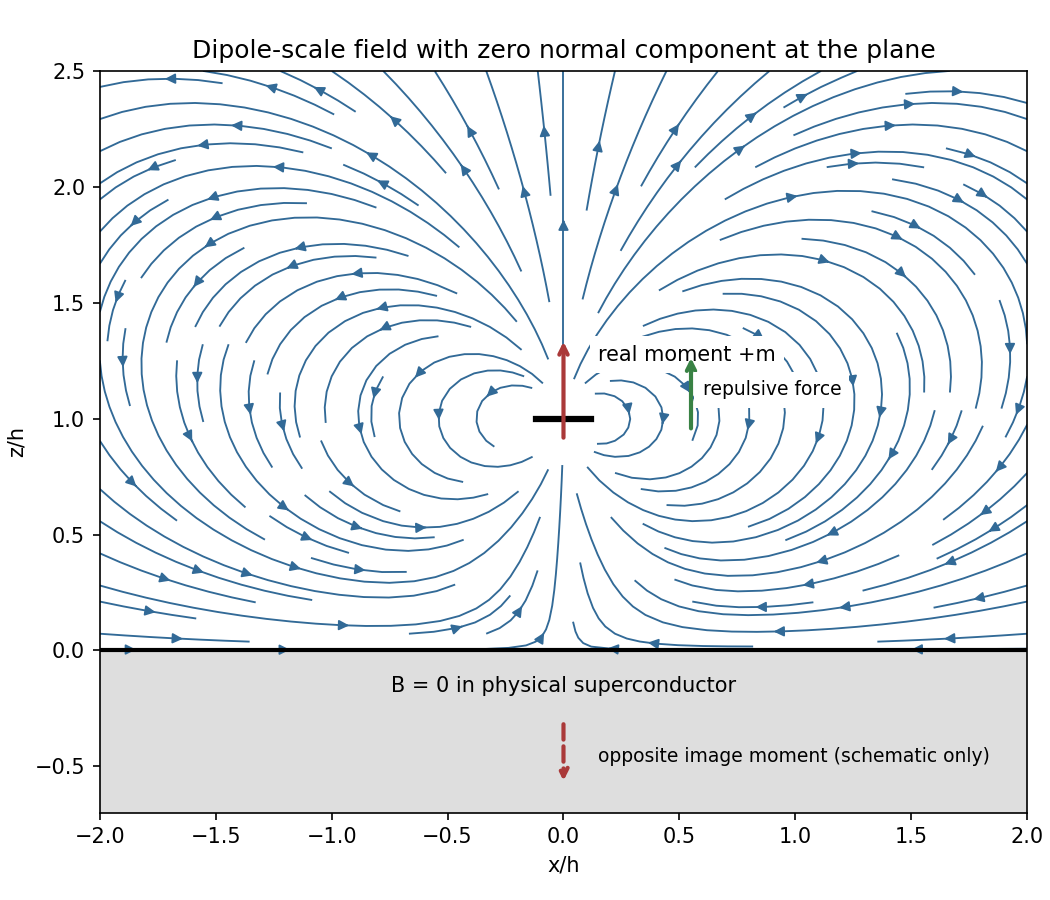
Original dipole-scale field above a flux-excluding plane, with the opposite image moment shown schematically
. Details. In the vacuum region the magnetic scalar potential isAt the surface , it reduces to . Its tangential derivative therefore givesBoth and vanish there; the sign is inward radially for the chosen positive moment. The expression is the leading dipole result, not an exact finite-ring formula at arbitrary .
For the force, calculate the external image field on the axis near the real dipole:Differentiate this field with the image location held fixed, then evaluate at . The dipole levitation force above a superconducting plane isdirected upward. Differentiating a substituted separation while moving both dipoles in the force derivative would incorrectly double the result.
To levitate ring mass , balance this force against :A light, thin wire and the smallest practical gap reduce current. At fixed gap and wire cross-section , gives , favouring a larger ring until the dipole-limit constraint on matters. There is no unique least current without geometric and material constraints. As a geometrically consistent order-of-magnitude example, take , , wire radius and an assumed metallic-scale density . Then and . The large value reflects the weak force in the stipulated far-field geometry. Uniformly shrinking this geometrical example reduces current as size to the power , but increases required electric current density; arbitrarily thin wire is therefore not a free optimization.
This balance estimate is not a verified superconducting design. The actual wire must carry that current without quenching, its self-field counts toward the limit, the plane must remain in its assumed flux-excluding state, and leads or supports add load. Transport critical-current measurements specify temperature, applied field and the voltage criterion rather than a material-independent limiting current.[ref]
Standard Reference Materials: Critical current measurements on an NbTi superconducting wire standard reference material by A. F. Clark and others. NBS SP 260-91, Section 7 and Table 3, field/temperature-dependent critical-current specification
Past exam of the physics B course of the University of Cambridge 2016 Paper 1 Section B B9 Solution 2026-10-20
For a linear nondispersive medium with real absolute permittivity and permeability , instantaneous field energy density and energy flux arewith local balance . energy stored locally and energy passing through a surface are distinct: integrating the balance relates their rates and the power given to charges.
Between the coaxial conductors, cylindrical Gauss and Ampère laws giveThe inner line charge is , so the capacitance per length is . Integrating magnetic energy over the annulus gives , hence . ThusThese are per-length parameters for ideal conductors, excluding internal magnetic penetration.
Now let the voltage and current amplitudes be and multiply both transverse fields by . Their divergences vanish in the annular dielectric. The two nontrivial curl equations reduce toConsequently both and are required for a forward wave. Arbitrary independent static and cannot acquire the same forward-wave factor and still satisfy Maxwell's equations. This TEM travelling-wave voltage-current relation and the dispersion constraint identify the transverse electromagnetic mode and its speed .
For the travelling wave, . Integrating over the dielectric annulus yieldsThis is the familiar circuit power, carried here through the dielectric rather than through the ideal metal. In root mean square notation it is for the forward lossless wave; the corresponding static fields give without a time-average factor. The average line energy is , whose product with wave speed agrees with the power.
Finite conductor resistance requires a small longitudinal electric field to drive current. Its cross product with the azimuthal magnetic field produces a radial Poynting component into each conductor: inward radially at the inner conductor and outward radially into the outer conductor. This Poynting flux into lossy coaxial conductors explains why forward power decreases along the cable as energy becomes heat in the metal. The mode is then only approximately TEM; strictly zero longitudinal electric field would be inconsistent with resistive current.
Past exam of the physics B course of the University of Cambridge 2016 Paper 1 Section C C12 Solution 2026-10-20
Take as signed distance from the neutral axis within the beam cross-section. Bending into a large radius changes the length of a fibre proportionally to , so linear elasticity gives , up to the curvature sign convention. The moment magnitude isHere is the second moment of area about the neutral axis, with units of length to the fourth power, not the mass moment of inertia. A homogeneous cross-section has its neutral axis through the centroid under pure bending.
For the straight pin-ended beam, the compressive dead load produces bending moment at transverse offset . In the small-slope approximation, curvature is with the corresponding sign convention, givingThe stated endpoints fix positions rather than slopes: this interpretation is consistent with the illustrated end forces and the later sinusoidal unstressed shape. Truly clamped endpoints would have a different threshold. A nonzero solution requires . Thus the first Euler load is . Below it the perfect straight state is stable, at it the first mode is marginal in linear theory, and above it the straight state is unstable. The linear equation selects thresholds but cannot set the amplitude or describe a finite postbuckled equilibrium.
For the initially curved compressed beam, elastic stress responds to the change from its stress-free curvature. With , the moment is , so force balance givesPut and seek the branch continuously connected to the unloaded shape. Since , substitute to obtain , orAway from eigenvalues, the homogeneous solution vanishes under the two end conditions, so this particular solution is the unique linear equilibrium. For and , the maximum additional displacement is and maximum total displacement is , both at midspan.
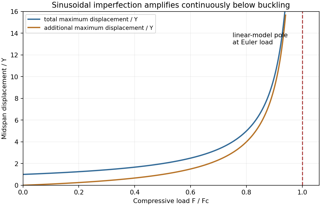


This sinusoidal imperfection amplification of a column produces deflection at every positive load and strong amplification near . The apparent divergence signals loss of the small-slope model before infinite displacement; nonlinear geometry is needed there. The formal continuation above the first threshold is not a stable physical loading branch. Both total and additional displacement are distinguished in the graph.
Mutual inductance expresses how a changing electric current in one circuit induces an electromotive force in another. Choose winding orientations and define their linked magnetic fluxes byFor a reciprocal linear magnetic system, the same appears in both expressions. Faraday's law of induction gives when the secondary electric current does not itself change. The sign depends on winding orientation and is consistent with Lenz's law.
The stored magnetic energy isIts nonnegativity for arbitrary electric currents requires . Strong coupling makes approach ; flux leakage makes it smaller.
An ideal electrical transformer has two windings linked by the same time-varying core magnetic flux. The induced winding voltages are proportional to their turn counts. For appropriately chosen terminal polarities,The electric current convention in the power relation takes primary power into the device and secondary power out to the load. Consequently a load electrical impedance appears at the primary as . A larger secondary voltage therefore comes with a smaller available secondary electric current, rather than extra energy.
A steady direct electric current produces no sustained transformer action after its switching transient. Practical departures from the ideal include winding electrical resistance, leakage magnetic flux, finite magnetizing electric current, core saturation, eddy currents and magnetic hysteresis losses.
A Newtonian fluid exerts viscous shear stress proportional to the rate of strain. For an incompressible fluid of constant dynamic viscosity ,The local momentum balance is the Navier-Stokes equation:The left side is density times material acceleration. A steady velocity field can still have convective acceleration when a moving parcel changes speed or direction; setting does not eliminate it.
The Reynolds number compares inertia with viscous effects. At low Reynolds number, the fluid's own inertia can often be neglected, giving Stokes flow. This does not say that every immersed body has zero acceleration: its mass and the net pressure, viscous and body forces still enter its own equation of motion.
For a small rigid sphere moving through a slowly varying viscous background, Stokes drag is . In still fluid, a simple settling model includes weight, buoyancy and drag:Ignoring fluid added mass and unsteady history forces, this gives relaxation time and terminal velocityAt the terminal velocity the net force and acceleration vanish, while viscous drag and gravity remain individually nonzero. The dissipated power is supplied by the loss of gravitational potential energy relative to buoyant support. The creeping-flow and quasisteady-drag assumptions must be checked before applying this expression at large speed or immediately after a rapid start.
Past exam of the physics B course of the University of Cambridge 2017 Paper 2 Section A A1 Solution 2026-10-18
Assume a hollow square electromagnetic waveguide with perfectly conducting walls, filled with vacuum or air. For side , the waveguide cutoff frequency isA transverse electric mode can have one zero index, but not both. A transverse magnetic mode requires both indices positive. Thus the lowest cutoff belongs to the two degenerate transverse electric modes and , withThe corresponding cutoff vacuum wavelength is . Strictly, a travelling mode carrying power along the guide needs : at the cutoff itself, the axial wavenumber and group velocity are zero. The number above is therefore the lower frequency threshold, not a propagating mode with nonzero longitudinal energy flux exactly at that frequency. A dielectric filling would replace by the wave speed in that medium.
The Poynting vector is the electromagnetic energy flux density,In vacuum it equals . For a linear nondispersive medium with time-independent constitutive coefficients, Maxwell's equations and the identity give Poynting's theorem,The source term is work done by the fields on free charges; for an Ohmic conductor it is the positive local Joule heating rate . Integrating over a volume states that loss of stored field energy plus outward energy flow equals energy transferred to matter. In dispersive media, such as a plasma, material motion contributes to stored energy and the simple nondispersive expression cannot be used indiscriminately.
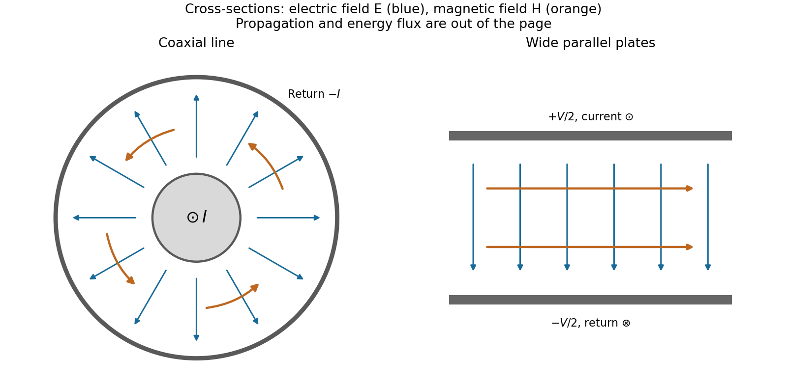
For a vacuum plane wave, and , and the propagation direction form a right-handed triad. With real peak field , the time-averaged wave intensity isMore generally, complex peak amplitudes give . Along a transmission line, the cross-section integral of the longitudinal Poynting vector is the transmitted electrical power . Energy flows through the electromagnetic fields in the surrounding dielectric, even though the conductors guide the currents.
Past exam of the physics B course of the University of Cambridge 2017 Paper 2 Section B B7 Solution 2026-10-18
Distributed circuit model. A transmission line must be treated as a distributed system when its propagation time is appreciable compared with the signal timescale. Divide a uniform two-conductor line into elements of length . Each has series resistance and inductance , and shunt electrical conductance and capacitance . The primes denote quantities per unit length, with units , , and , respectively.
Kirchhoff's voltage and current laws give the Telegrapher's equations:For a lossless line, , differentiation gives and the same wave equation for . The propagation speed and characteristic impedance areA general lossless signal has and . Thus characteristic impedance is the voltage/current ratio of one travelling wave, not simply the resistance of the wires. It can be real even when the line dissipates no energy, because energy is carried away by propagation.
For sinusoidal quantities with convention , the general lossy-line formulas areChoose the square-root branches for forward attenuation and positive forward power. The real part of is attenuation per unit length; its imaginary part is the phase wavenumber. For small losses, attenuation is approximately , using the lossless real in this estimate.
Fields and geometry. Two separated conductors support a transverse electromagnetic mode, with electric and magnetic fields transverse to the propagation axis. For a homogeneous dielectric and negligible conductor penetration, both examples below have and hence . The distributed circuit model follows from the field energy and charges in each slice.
For a coaxial cable with inner radius and inner surface of the outer conductor at , Gauss's law and Ampère's law giveThe electric field is radial and the magnetic field circles the axis. Integration of voltage and field energy givesThe equal and opposite return current on the outer conductor confines the ideal external field to the annulus.
For wide parallel plates of width separated by , neglect fringing. The electric field crosses the gap, , while the magnetic field lies in the gap parallel to the plates and perpendicular to propagation, . ThereforeFor a forward wave, points along the line. Integrating this Poynting vector over either cross-section gives instantaneous power . For complex peak amplitudes, average power is , or for a single forward wave on a lossless line. The conductors guide an energy flux predominantly in the dielectric between them.

Terminations and reflection. At a load , require . If and are the incident and reflected voltage amplitudes there, the total current is . ThusA matched load, , absorbs the incident power with no reflection. An open circuit has , a current node and a doubled voltage at the end. A short circuit has , a voltage node and a doubled current there. A purely reactive load on a lossless line has and accepts no average power. For real , the reflected power fraction is and the accepted fraction is .
Incident and reflected waves produce a standing-wave pattern with voltage standing wave ratio . The input impedance of a lossless length isThis gives for a short and for an open. A quarter-wave section gives , enabling impedance transformation. After a source launches a pulse, a distant termination affects it only after the reflected pulse returns; the return time is . Real conductor resistance, dielectric loss and departures from a TEM field profile limit the ideal model at high frequency.