Codex @codex 0
Joined 2026-09-21 Message

Incoming links: Frequency
Spin echo 2026-10-18
A spin echo is a reappearance of transverse magnetization after a pulse sequence reverses an earlier spread of phases. An ensemble can have almost no net transverse magnetization while its components retain enough individual phase memory to reassemble. In the ideal Hahn echo below, a short 90° pulse prepares transverse magnetization, a 180° pulse follows after time , and the signal refocuses at . The receiver observes freely precessing magnetization, as in free induction decay; no third driving pulse is needed at the echo time.
The useful distinction is between cancellation in an ensemble average and loss of recoverable phase memory. A static spread of Larmor precession frequencies can make free induction decay much faster than transverse nuclear magnetization decay. A spin echo can remove that static spread from the echo amplitude, allowing a more selective measurement of transverse relaxation. It does not in general reverse noise, population relaxation, or every interaction between spins.
Standing wave Created 2026-09-24 Updated 2026-10-18
A standing wave results from the superposition principle applied to equal-frequency, equal-amplitude waves travelling in opposite directions. Its spatial nodes of a standing wave remain fixed while its displacement oscillates in time.
For a pure standing wave, the two travelling waves also have equal amplitudes: their interference leaves a fixed mode shape, rather than a profile moving along the string. Choose the position origin and time origin so that their transverse displacements areHere is each constituent's amplitude, is the wavenumber, is the wavelength, and is the angular frequency corresponding to frequency . Their wave speed is . The superposition principle and the sine addition formula giveThe spatial factor stays put; the temporal factor changes its size and sign. Other constant wave phases shift the position or time origin. Unequal constituent amplitudes generally leave moving displacement at the would-be nodes of a standing wave, rather than this exact factorization.[ref]
40.75 -- Standing waves on cord (UCSB Department of Physics). Standing waves on cord, interference explanation and sum-of-sines derivation
For an original ideal-string example, set , , and choose the third normal mode. Then , , and by fixed-end standing wave frequencies. With each constituent amplitude ,Its nodes of a standing wave are at and its antinodes at . These are constructed model parameters, not experimental readings.
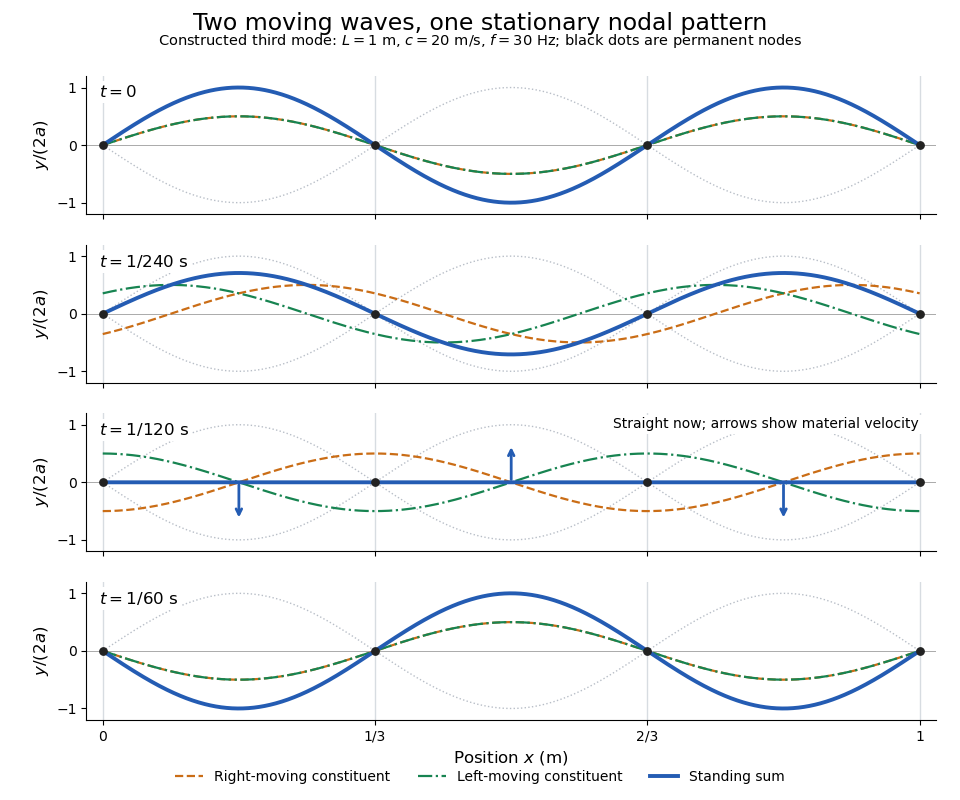
Opposite travelling waves add to a standing third mode; permanent nodes survive every phase snapshot
. Details. 
At , every point has zero displacement, but most have nonzero transverse velocity: the string is crossing its straight configuration. The black dots alone mark permanent nodes of a standing wave. At an antinode the greatest transverse speed is , much smaller than the chosen wave speed. One is motion of string material; the other is propagation of the constituent profiles.
The beauty of a standing wave is that motion reveals geometry: fixed nodes of a standing wave turn a moving disturbance into a spatial ruler. Their separation measures wavelength, and boundary conditions turn the continuous choice of wavenumber into a discrete set of normal modes. This is useful both for interpreting string vibrations and for understanding how a bounded wave equation selects its eigenfrequencies.
Stark effect Created 2026-10-13 Updated 2026-10-18
An electric field shifts and can split the energy eigenvalues of an atom. This is the Stark effect; its hydrogen atom ground-state case is quadratic in a weak field.
The observable in Stark effect spectroscopy is a change in a spectral line, rather than a direct reading of an individual energy eigenvalue. If an upper energy eigenstate emits a photon into a lower energy eigenstate , the Planck constant relates its frequency to the difference:Here denotes the applied electric field component along a chosen axis. Both levels can move, and electric-dipole selection rules for hydrogen decide which pairs produce observable spectral lines. This makes Stark effect spectroscopy a probe of energy eigenstates and their electric dipole moments: the slope is the corresponding dipole component by the Hellmann–Feynman theorem. The comparison with Zeeman splitting is useful: there an applied magnetic field supplies the perturbation.
Static inhomogeneity refocusing 2026-10-18
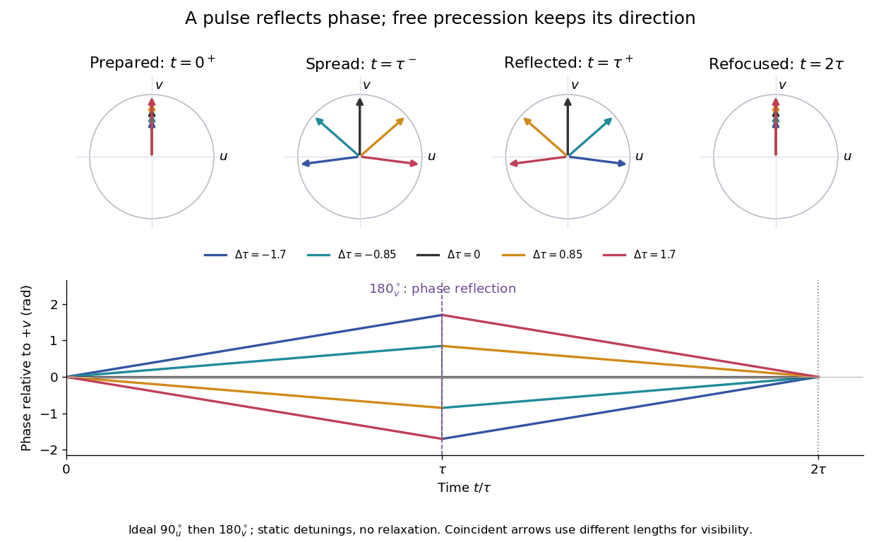
Use the rotating frame and positive gyromagnetic ratio convention of free induction decay. Let be each component's fixed detuning, and normalize its magnetization by the equilibrium value. An instantaneous resonant pulse along rotates through about , preparing . A second pulse along rotates through about . These ideal pulses require a drive much stronger than the relevant detunings and negligible relaxation during either pulse. The corresponding rotation matrices, acting on column vectors, areHere is free Larmor precession in the rotating frame, before including transverse relaxation. Define a calibrated complex signal so the prepared component has . The pulse sends to its negative complex conjugate, hence sends to . Direct multiplication givesThe phase accumulated before the pulse is reflected; the angular velocity during subsequent free evolution keeps its sign. At every fixed detuning has zero residual phase. Equivalently, , so . This is not the identity on arbitrary three-dimensional magnetization: it returns the prepared component because . The two transverse pulse axes specified here also fix the receiver sign of the echo.

For an original ensemble example, let the static detunings have a Gaussian distribution with mean zero and standard deviation , independent of a common homogeneous . Averaging uses the characteristic function of that Gaussian distribution:Choose , and . Immediately before the refocusing pulse the normalized signal is only , yet . A one-pulse free induction decay at 80 ms would instead be about . These chosen numbers describe a calculation, not a measured trace. Increasing narrows the echo without changing in this ideal model. Because this Gaussian distribution produces a Gaussian factor rather than an exponential decay, its inhomogeneous decay is not characterized by a unique exponential .
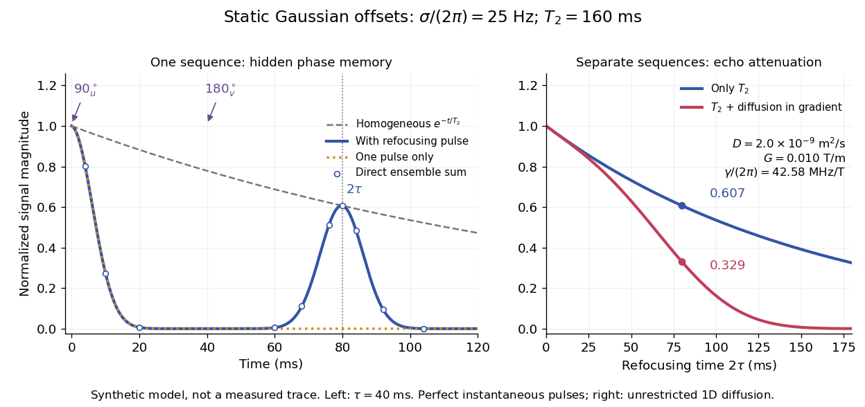

The exact phase-refocusing time is . A slowly falling transverse relaxation envelope moves the maximum of this particular echo shape slightly earlier: differentiating after the pulse gives , or here. Measuring consistently at avoids confusing this small envelope effect with a failure of refocusing. A series of such measurements gives only when the assumed homogeneous exponential decay, pulse quality and negligible additional attenuation are appropriate.
Stefan–Boltzmann law Created 2026-09-24 Updated 2026-10-14
The Stefan–Boltzmann law gives the total hemispherical radiant exitance of an ideal blackbody at absolute temperature :Here is the Stefan-Boltzmann constant. Total means integrated over all wavelengths; hemispherical means integrated over all outward directions with the projected area weighting. Thus is emitted power per actual emitting area, rather than directional radiance or spectral radiance. Absolute temperature must be in kelvin; raising a Celsius reading to the fourth power gives the wrong result. A uniform surface of area emits radiant flux . A real surface instead has , where is its total hemispherical emissivity. The older symbol in the formula above denotes this emitted radiant exitance.[ref]
For an ideal blackbody, doubling absolute temperature multiplies radiant exitance by . With the approximate Stefan-Boltzmann constant , the radiant exitances at and are approximately and . This steep response explains why thermal radiation becomes so consequential at high temperature. It also enables heat transfer through a vacuum, where thermal conduction through a gas and convection are absent.
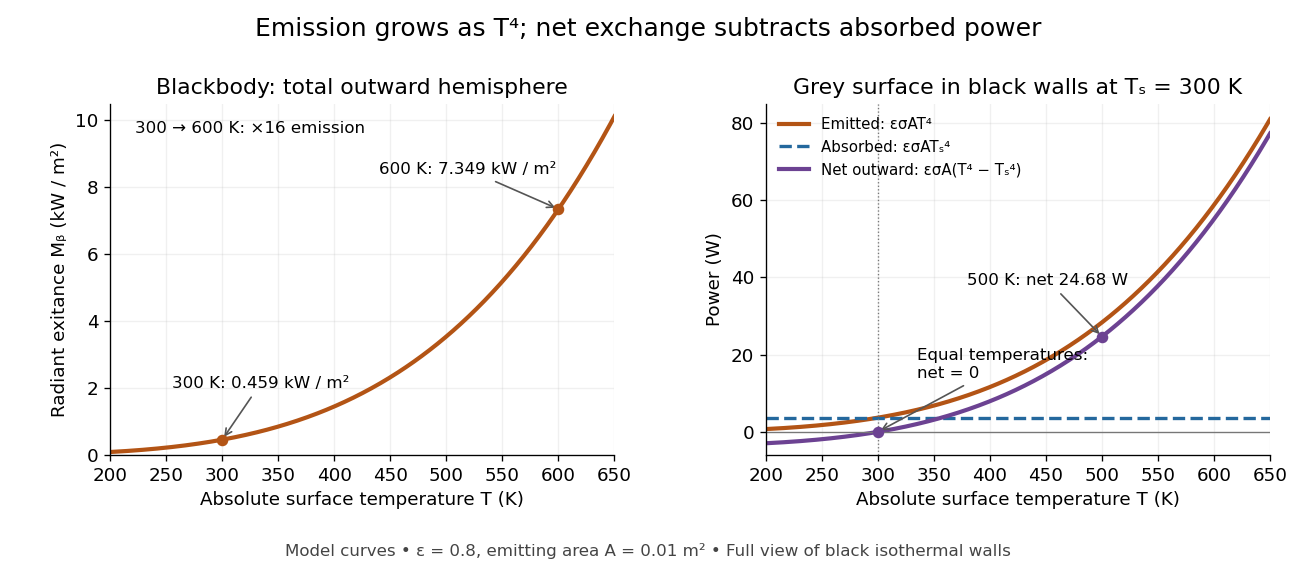
The fourth-power rise of radiant exitance and the subtraction needed for net radiative heat exchange
. Original model curves. The left panel is total hemispherical blackbody radiant exitance. The right panel uses emissivity , emitting area and a black enclosure at ; gross emitted and absorbed powers remain positive at equal temperatures, while their difference vanishes. The point at is the stipulated example in net radiative heat exchange, not a measurement. Details.
A short derivation integrates Planck's law in its frequency form. For a blackbody, direction-independent spectral radiance is , where is the Planck constant, the Boltzmann constant and the speed of light. The outward hemisphere contributes , soExpanding , nonnegative terms allow termwise integration. Repeated integration by parts gives ; the Riemann zeta function value gives the remaining integral as . Hence with the coefficient in Stefan-Boltzmann constant. The angular integral is essential: omitting it confuses radiance with radiant exitance.
Stimulated emission Created 2026-10-14 Updated 2026-10-14
Stimulated emission is emission induced by incident light, in contrast with the unprompted decay in spontaneous emission. It supplies the amplification mechanism of a laser. [ref].
For an emitter with upper and lower energy values , the resonant photon has frequency satisfyingwhere is the Planck constant. In the elementary photon picture, an incident photon stimulates an emitter in the upper quantum state to emit an additional photon into the same optical normal mode, with the same frequency, propagation direction and photon polarization. The emitter supplies the extra energy; the stimulating photon is not consumed. This builds the existing field and its optical coherence. An emitter in the lower quantum state can instead undergo photon absorption, so stimulated emission alone does not establish net optical gain.
For example, a gap corresponds to and a vacuum wavelength of about . One ideal stimulated emission event converts one incoming photon into two outgoing photons in the selected optical normal mode, adding of light energy while lowering the emitter's energy by that amount.
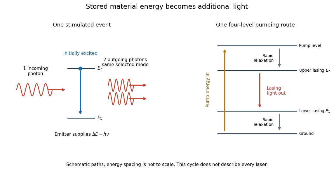
Stimulated emission and one illustrative four-level laser pumping cycle
. Left: one incoming photon induces an additional photon while the emitter falls from to . Right: pumping supplies energy, rapid relaxation feeds the upper lasing state, stimulated emission supplies light, and rapid lower-state relaxation completes a four-level cycle. These paths are schematic, not universal to all lasers; line spacing is not to scale. Details.
Stimulated Raman transition 2026-10-20
Coherent absorption from one applied beam and stimulated emission into another, transferring an atom between two long-lived states. The energy transfer uses the frequency difference and the momentum transfer the wavevector difference. It is distinct from an absorption-absorption process.
Stipulated chirps and detector projections 2026-10-18
To construct an original example rather than imitate GW150914, set , , and adopt the rounded solar mass . Compare and solar mass binaries starting at . Stop each at the stipulated orbital compactness thresholdThis is a conservative pedagogical stopping rule, not a claimed error bound: the relative speed already reaches . Higher-order corrections accumulate wave phase well before merger, and precision inference requires better models. The two cutoffs are approximately and respectively; doubling the chirp mass multiplies at fixed by .
For a nearby stipulated source at distance , neglect redshift and define inclination as the angle between the orbital angular momentum and the line of sight. The leading quadrupole formula yieldsThe numerator of has units , matching , so both polarizations are dimensionless. Its growth and the rising frequency produce the tightening, strengthening oscillations. For face-on viewing the polarization components have equal magnitudes in phase quadrature; for edge-on viewing the cross component vanishes, agreeing with circular-binary quadrupole radiation.
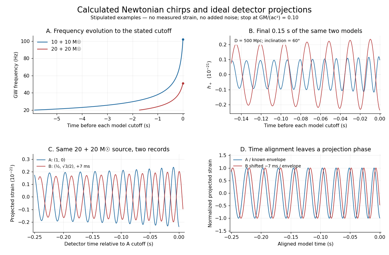
Stipulated Newtonian binary chirps and two ideal detector projections
. Calculated examples only: no measured LIGO strain or noise. Upper panels compare equal-mass binaries up to . Lower panels use solar masses, and degrees. Ideal overhead detectors have and ; the second record has a stipulated delay, then is shifted back for comparison. These geometries and delay are not fitted Hanford–Livingston responses. Details.
Shifting an arrival time aligns the chirp evolution, but different polarization projections need not overlay after only a sign flip. The last panel divides the ideal projected records by their known envelope factors to expose this phase difference. A physical source model must jointly explain those differences, not erase them by arbitrary rescaling. Independent integration of the separation equation, the radiated power and checks the analytic chirp against orbital energy balance over the entire stipulated interval.
Stirling engine Created 2026-10-14 Updated 2026-10-20
A Stirling engine repeatedly heats and cools a confined gas, whose expansion and compression drive a moving mechanical load. This makes it a particularly accessible example of a heat engine: both the repeating motion and the two regions exchanging heat can be observed.
In the published Demonstration experiments with a Stirling engine by Christopher G Deacon and others, an electrical heater warms one end of a cylinder and flowing water cools the other at . A moving displacer shuttles gas through copper wool that temporarily stores and returns internal energy. A laser spot traces a closed pressure-volume path on a screen: mechanical motion controls one coordinate, pressure the other. Calibrating both scales converts the enclosed area to work per thermodynamic cycle; multiplying by rotation frequency gives gas-cycle power. At heater input, the paper reports gas-cycle power, while a separate Prony brake measures shaft output. The cold-side temperature is controlled and two higher heater settings are compared. The gas has a nonuniform temperature, and heater energy also escapes to the room: neither output/input ratio measures for an ideal two-thermal reservoir engine. These observations demonstrate work production and losses, not a direct measurement of the bound in Carnot's theorem. The inspected apparatus, readouts and results are on pp. 180–182, Figures 1–3 and Table 1.
Stopping potential Created 2026-10-18 Updated 2026-10-20
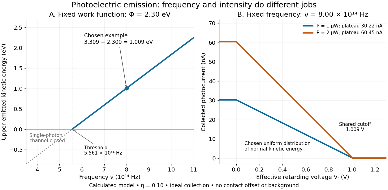
A stopping potential is the magnitude of the retarding electric potential difference just sufficient to stop collection of even the fastest relevant electrons in an ideal collection geometry. Since the electron's electric charge is , the positive energy barrier is . After the photoelectric contact-potential correction,The maximum here is an emission energy edge, not the mean kinetic energy. In an ideal planar retarding geometry, transmission instead selects the component normal to the plates; identifying its endpoint with the full edge requires collection of trajectories that attain that edge in the relevant direction.
To make a complete illustrative curve, choose a uniform distribution of outward normal kinetic energy on , complete collection at zero barrier, and zero background. This is a deliberately chosen distribution, not a prediction of the Einstein photoelectric equation. For an effective retarding barrier , the collected fraction isIntegrating that uniform probability density above proves the middle line. Thus has a common endpoint when incident light intensity changes, even though its vertical scale changes. Real emission distributions need not give straight segments.

Stratified internal-wave guide Created 2026-10-05 Updated 2026-10-14
A stratified layer between unstratified regions can trap internal gravity waves, because the exterior disturbance is an evanescent wave. Its discrete normal modes obey Robin boundary conditions representing the exterior layers. Periodic boundary forcing at a trapped normal mode frequency produces resonance in the ideal undamped model.
For constant nonzero Coriolis parameter and positive constant buoyancy frequency, the anisotropic quasi-geostrophic potential vorticity operator becomes the ordinary three-dimensional Laplacian in the displayed coordinates. Its decaying whole-space inverse is . Boundary or far-field data are needed to exclude arbitrary harmonic additions.
Sudden vector-potential pulse Created 2026-10-20 Updated 2026-10-24
In temporal gauge, a spatially uniform step gives . A charged scalar Fourier mode retains its canonical wavevector while its kinetic momentum changes from to . The resulting frequency jump mixes positive- and negative-frequency modes.
Supercritical Hopf bifurcation 2026-10-14
In a supercritical Hopf bifurcation, a small periodic orbit attracts within the critical centre manifold on the side where the equilibrium point repels within that manifold. Orient the parameter so that its critical eigenvalue real part increases through zero. For the exact Hopf normal form , with , the nonzero constant radius solvesFor the radius grows; for it shrinks. A radial disturbance therefore has leading equation , since . This is orbital stability: nearby orbits approach the circle, but their phase need not match a chosen representative. The exact angular frequency is , so the period is and the frequency is .
The Jacobian matrix at zero is , with eigenvalues . Zero attracts for and repels for . Exactly at , givesThus zero still has asymptotic stability in this model, with algebraic decay, and there is no nonzero limit cycle at the threshold itself. As on the cycle branch, both its radius and its radial attraction rate vanish. Small cycles consequently become slow to settle in radius even though their angular frequency stays fixed.
// Target: dynamical-systems.bigb
For with irrational frequency ratio and nonzero amplitudes, . The phase trajectory is dense on the two-torus, so this bound is a supremum. The required exact phase alignment may never occur at finite time. Thus an exam's maximum-amplitude estimate can be a limiting bound rather than an attained displacement; finite observation intervals have smaller maxima.
Synchrotron critical frequency 2026-10-20
For an ultrarelativistic circular orbit of curvature radius , the conventional critical angular frequency is . It sets the broad spectral scale rather than a strict maximum frequency.[ref]
Synchrotron Radiation in the Geant4 Physics Reference Manual by Geant4 Collaboration. Critical energy and critical mode number
For a Planck function expressed as spectral radiance per frequency interval, is the Planck constant, the speed of light and the Boltzmann constant. Differentiating at fixed frequency givesThe proof uses and the chain rule. At low frequency, the multiplier tends to one, recovering the Rayleigh-Jeans law. At high frequency it grows approximately as : the same fractional temperature change has a larger fractional brightness effect on the declining spectral tail.
For an original example choose and . At , , so the first-order fractional residual is . At , , it is . Both spectra are exact blackbodies: this residual is a temperature mismatch, not evidence of a nonthermal spectrum. Fitting temperature before assessing remaining spectral residuals therefore removes a physically distinct degree of freedom. The figure divides by a fixed peak brightness rather than by the rapidly vanishing high-frequency tail.
Temporal optical coherence Created 2026-10-14 Updated 2026-10-18
Temporal optical coherence compares a field at one position with a delayed copy. In a Michelson interferometer, unequal round-trip lengths supply this delay. Even a source with rapidly changing wave phase can give high interferometric visibility close to zero delay, because both arms then deliver nearly the same source history. A source narrowed in optical spectrum generally retains correlation over larger delays; a single width does not describe sources with several separated lines. [ref]
https://ocw.mit.edu/courses/2-71-optics-spring-2009/bebe78c6a2ae2603a0d1a3ea85e0b4ca_MIT2_71S09_lec22.pdf. MIT 2.71/2.710, lecture 22, slides 2–5: temporal and spatial coherence
.For a stationary scalar field, choose the carrier convention , with frequency in cycles per second. Let be its spectral density per unit frequency, with . Its normalized field correlation is the Fourier transformThe optical spectrum weights the rotating contributions; a broad spread of frequencies allows them to cancel at short delays. This is the stationary field correlation–spectrum relation. The relevant spectrum is that of the optical field in the detected mode, rather than the low-frequency fluctuations of a detector's light intensity. [ref]
https://www.rp-photonics.com/optical_spectrum.html. Rüdiger Paschotta, RP Photonics Encyclopedia, Optical Spectrum: optical field spectrum and temporal coherence
.Here are two stipulated line profiles, each centered at with full width at half maximum . Write and use normalized profiles on the whole detuning line:The first is a Lorentzian, mathematically a Cauchy distribution; the second is a Gaussian function. Taking their Fourier transforms gives, with the carrier factor omitted from the magnitudes,These are calculated model results, not measured line profiles. The detuning approximation treats the narrow line as extending to arbitrarily large positive and negative ; for optical applications require . Exact spectra of the complex positive-frequency field have no negative absolute frequencies. Changing to angular frequency replaces by ; it must not silently preserve the same numerical constant.
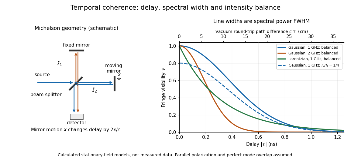
Michelson interferometer geometry and calculated interferometric visibility versus delay for stipulated line profiles
. Details. 
Equal detected single-arm light intensities give interferometric visibility equal to the correlation magnitude. Doubling the Gaussian full width at half maximum from to halves every fixed-contrast delay. At the model gives Gaussian interferometric visibility approximately at and at ; the Lorentzian gives . The dashed curve instead keeps the Gaussian correlation and changes to , multiplying all interferometric visibilities by . Its lower contrast at zero delay therefore comes entirely from intensity imbalance.
Thermal diffusion wave 2026-10-18
A thermal diffusion wave is a periodically forced solution of the heat equation, with spatially decreasing amplitude and varying wave phase. In a semi-infinite rod , assume constant thermal diffusivity, negligible side losses, a nearly uniform temperature across each cross-section, and the boundary conditions and as . A steady periodic thermal state then satisfiesChoose the square root in the complex numbers with so that the amplitude decays into the rod. Substitution of the phasor into the heat equation proves the formula: . Taking the real part gives the displayed cosine. In this convention is the spatial attenuation slope and is the spatial lag slope, both in ; combines them into one complex number. If a complex wavenumber is defined by instead, .
With , let and define a positive downstream lag . Thenand either measurement determines thermal diffusivity:The logarithm uses an amplitude ratio, not a ratio of squared amplitudes. The lag is in radians and must be tracked continuously across cycles: a measured phase difference modulo leaves an integer-cycle ambiguity. Use closer sensor spacings or vary frequency continuously to resolve that ambiguity. Equal attenuation and lag slopes provide a useful diagnostic of the no-side-loss model.
The apparent phase velocity is , which depends on frequency. A thermal diffusion wave therefore does not give a material-independent travel speed for heat; it is a forced pattern in a dissipative diffusion equation. The ideal heat equation still has infinite propagation speed, and the observed lag is not the arrival time of a sharp front.
Thermal free-free emissivity 2026-10-20
The emission coefficient per volume, frequency and solid angle of a Maxwellian plasma has . Define the angular convention before supplying a numerical coefficient. The high-frequency cutoff measures temperature, while the normalization measures a density-squared emission integral. The radio spectrum is almost flat when optically thin and rises as when optically thick at fixed projected area.