
Endosymbiotic gene transfer moves genetic material from an endosymbiont or its descendant organelle into the host genome, notably the nuclear genome. A transferred DNA segment can remain silent. For a transferred gene to replace an organelle-encoded function, nuclear gene expression must work and its protein must reach the right compartment through organelle protein import. Transfer of DNA and transport of proteins are distinct processes in opposite directions. [ref]
Experimental Reconstruction of Functional Gene Transfer from the Tobacco Plastid Genome to the Nucleus by Sandra Stegemann and Ralph Bock. Introduction, p. 2869, and Discussion, p. 2875: transferred sequences and the additional targeting problem
Gene loss and endosymbiotic gene transfer are different: absence from an organelle genome does not by itself show that a functional nuclear copy exists. Conversely, an imported protein may derive from a host gene rather than a transferred gene. The surviving organelle genome is therefore a partial record, not a complete inventory of either ancestral bacteria or the modern organelle's machinery. [ref]
Origin and Evolution of Plastids and Photosynthesis in Eukaryotes by Geoffrey I. McFadden. “How to tame your symbiont”: losses, transfers, host recruitment and repatriation of proteins
Resemblance is a clue, not sufficient evidence of common descent. A small size, two surrounding membranes, division, retained DNA or bacterial-looking ribosomes does not uniquely identify an ancestor. Internal membranes exist outside these organelles, and a similar function can favor similar structures. The stronger question is whether independently examined molecular characters support the same historical relationship.
A concrete genomic observation is the mitochondrial sequence reported in 1997 for Reclinomonas americana: base pairs containing 97 identified genes, including four for a bacterial-type multisubunit RNA polymerase. This is a reported genome inventory, not a calculation from the pictured shape of a mitochondrion. Retention of such bacterial features strengthens the ancestry argument; a living Reclinomonas americana is not itself an ancestral eukaryote. The inspected abstract supplies these observations but not the detailed sequencing protocol or contamination controls, so those details are not attributed to this report here. [ref]
An ancestral mitochondrial DNA resembling a eubacterial genome in miniature by B. Franz Lang and others. Abstract, Nature 387 (1997), pp. 493–497: genome length, gene inventory and bacterial-type RNA polymerase
A sequence-based investigation obtains nucleotide sequences by DNA sequencing, identifies comparable genes, makes a sequence alignment and uses phylogenetics to infer relationships. The readout is a proposed relationship with support and uncertainty, not a photograph of an ancient encounter. Comparisons of plastid sequences with bacterial sequences support cyanobacterial ancestry, while the exact closest sampled cyanobacterial group has depended on the chosen data and inference. A bacterial affinity in one gene is weaker than coherent evidence across several genes and cellular systems. [ref]
Origin and Evolution of Plastids and Photosynthesis in Eukaryotes by Geoffrey I. McFadden. “The endosymbiont: when and who?”: alternative phylogenetic placements and lateral gene transfer
For such an analysis, useful checks include distinguishing organelle DNA from bacterial contamination, verifying sequence quality, comparing corresponding rather than unrelated genes, sampling several bacterial groups and testing sensitivity to the sequence alignment and evolutionary mathematical model. These are methodological requirements, not a claim that this article has rerun a particular published analysis. Horizontal gene transfer, gene loss and unequal evolutionary change can make an individual gene's history differ from a whole organism's history. A supported bacterial origin therefore need not identify an extant donor species, an exact date or the original mode of entry. [ref]
Origin and Evolution of Plastids and Photosynthesis in Eukaryotes by Geoffrey I. McFadden. “The endosymbiont: when and who?”: ancient origin and confounding lateral transfer
A state with a stationary electric charge distribution and no net drift of mobile charge driven by the electric field. A conductor in electrostatic equilibrium has zero interior electric field, while bound charges in an insulating material need not move to eliminate its interior field.
Faraday's ice pail experiment distinguishes redistribution of electric charge by electrostatic induction from transfer of electric charge by contact. Lower a charged body into an initially neutral isolated metal pail: an externally connected electrometer responds even though the body never touches the metal. Withdraw the body without contact and the response disappears. Repeat with conductive contact before withdrawal and a residual response can remain. The striking point is that an exterior response does not establish that the pail has gained net electric charge.
Apparatus and readout. A modern implementation uses two concentric wire-mesh cylinders: a 10 cm diameter, 15 cm high inner pail on insulating rods and a grounded outer shield. Connect the electrometer's signal lead to the inner pail and its reference lead to the shield. Momentarily ground and zero the signal assembly, then isolate it; the shield remains grounded. A charged disk on an insulating handle goes into the lower half without touching. The electrometer measures electric potential difference in volts, with sign determined by the lead connections. It does not directly measure electric charge in coulombs.[ref]
Basic Electrostatics System (ES-9080B), Instruction Manual 012-07227G by Cecilia Hernandez. Basic Electrostatics System, instruction manual 012-07227G, printed pp. 9–10, 13–15, Figure 1.1 and Procedure 1A
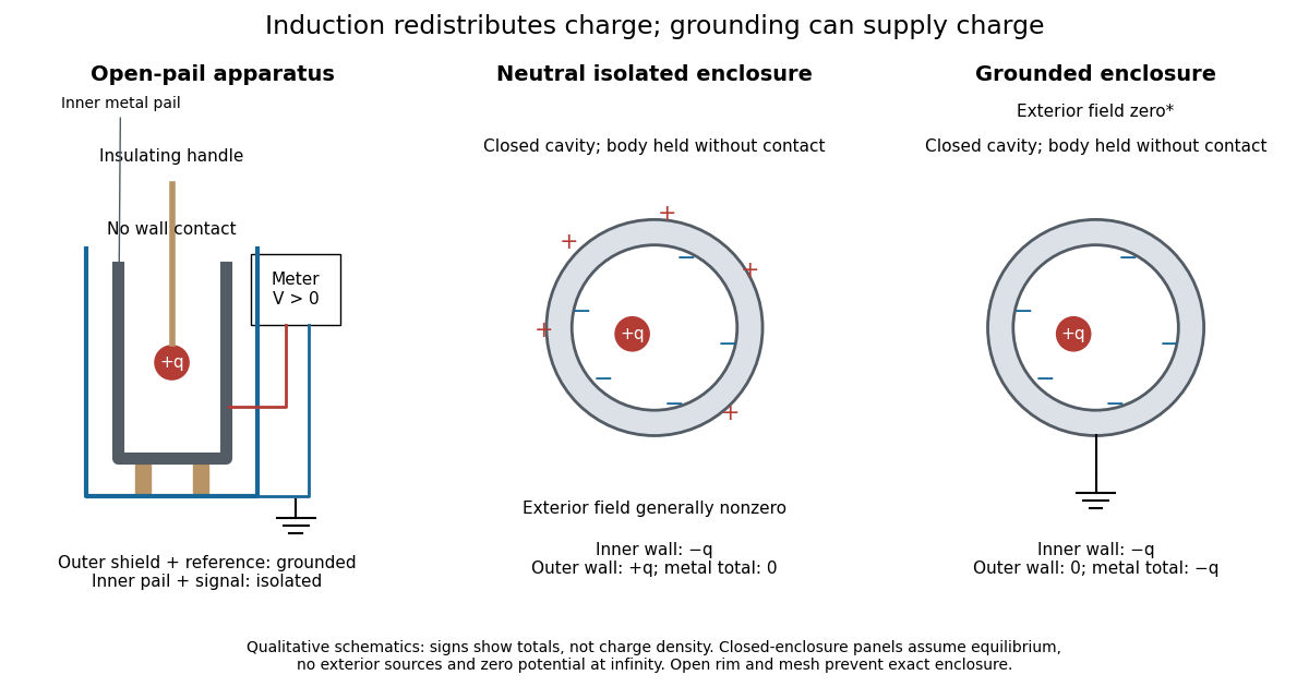
Faraday's ice pail experiment: apparatus and isolated versus grounded electric charge accounting
. Original qualitative schematics. The open pail approximates enclosure; the two closed cavity in a conductor panels stipulate exact enclosure, electrostatic equilibrium, no exterior sources and zero electric potential at infinity. Signs denote total electric charges, not a measured or uniform surface charge density. Details.
A charge ledger before contact. To separate exact reasoning from the open apparatus, first idealize the pail as a closed cavity in a conductor with one internal body of total electric charge . Let the isolated metal have total electric charge . The metal's electric field is zero at electrostatic equilibrium.[ref]
Ideal Conductors. Richard Fitzpatrick, Ideal Conductors, equations 2.124–2.126: zero field and constant potential in metal
A Gaussian surface enclosing the cavity in a conductor but lying wholly in the metal therefore has zero electric flux. Gauss's law and charge conservation giveFor and , the inner-wall total is and the outer-wall total is : the metal remains neutral. The exterior electric field can therefore be nonzero without any transfer from the body. The connected electrometer and signal cable belong to the same isolated conducting assembly and share its exterior electric charge. The zero-electric field assertion concerns metal, not the occupied cavity in a conductor.This ledger fixes totals, not the local surface charge density. Moving an off-center body changes the inner-wall distribution while its integral remains . With fixed outer geometry, fixed and unchanged exterior sources, Uniqueness of the Dirichlet problem together with the fixed total outer electric charge determines the same exterior solution: the outside cannot reveal the body's position or detailed internal distribution. For example, internal bodies with stipulated electric charges and give the same total exterior response as a single body with . Internal bodies with and can give a null exterior response while retaining a nonzero internal electric field. This is why a null reading cannot establish an empty cavity in a conductor.
Withdrawal is the control. Record a baseline, insert without contact, withdraw, and check return to baseline. After a fresh zero, repeat with the charged disk touching the inner wall, then withdraw and record the residual response. Finally zero the pail and reinsert the disk without contact to test remaining electric charge. Keep the operator grounded, discharge unwanted handle electric charge, and keep the unused charged disk distant. Dirty supports and humidity promote leakage. These controls separate transfer from electrostatic induction and stray coupling.[ref]
Basic Electrostatics System (ES-9080B), Instruction Manual 012-07227G by Cecilia Hernandez. Basic Electrostatics System, instruction manual 012-07227G, printed pp. 4–5 and 14–15, Procedure 1A steps 3–8: handle charge, withdrawal, contact and disk retest
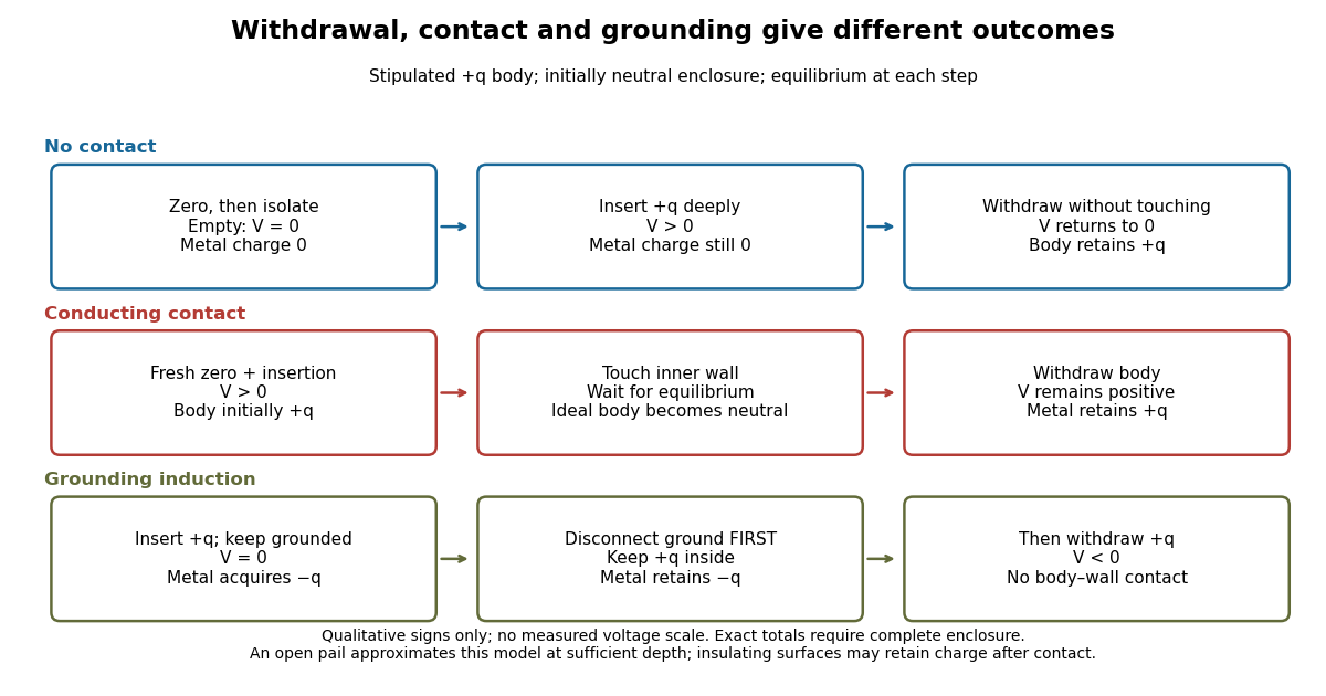

In the ideal contact test, the internal body is itself an electrical conductor and makes a conducting connection to the wall. After charge relaxation, body and enclosure become a single equipotential; the remaining charge-free void has zero electric field. The body then carries no excess electric charge on surfaces facing that void. Withdrawal without subsequent charging leaves total metal electric charge . A coated paddle can retain electric charge on insulating patches, so merely touching it does not guarantee complete transfer. A residual reading establishes some transfer under the controls; the disk retest checks the stronger claim of complete transfer. The ideal argument assumes no leakage and no relevant contact-generated charging.
Grounding changes the ledger. With no exterior sources and zero electric potential at infinity, a closed grounded enclosure has zero exterior electric field, inner-wall electric charge and zero outer-wall electric charge.[ref]
The Feynman Lectures on Physics, Volume II by Richard Feynman and others. II.5, §5–10, final shielding argument: a closed grounded conducting shell separates the two electrostatic problems
Consequently, disconnecting ground before withdrawal retains total metal electric charge , which moves to the exterior after withdrawal. Keeping ground connected during withdrawal instead restores zero electric charge. A lasting opposite-sign response can therefore arise through grounding without body–wall contact.For the real open pail, no Gaussian surface lying wholly in metal closes over the mouth. Increasing insertion depth and seeking a stable response tests whether enclosure is a good approximation; mesh openings, rim proximity and nearby objects limit it. In a fixed-geometry approximation, the positive insertion response obeys , where is the effective capacitance of the pail, shield, cable and electrometer input. Changed geometry changes that conversion. Wait for charge relaxation and instrument settling at each step, while keeping the observation short compared with leakage. The experiment probes settled electrostatics; it does not establish shielding against arbitrary changing electromagnetic fields.
An electron subshell groups the allowed electronic quantum states within an electron shell by their orbital angular momentum quantum number . Labels and mean and , respectively; their capacities are two and six electrons. The leading number in identifies the electron shell, while identifies the electron subshell.
The neutron excess is the number of neutrons minus protons per baryon. A mixture of carbon-12 and oxygen-16 has zero neutron excess, while neon-22 contributes per baryon in that isotope. Thus a neon-22 mass fraction gives . A nonzero excess shifts iron-group ashes from symmetric nickel-56 toward neutron-rich isotopes, even before additional weak reactions occur.
For optically thin lines with local ratio , their integrated observed ratio is . Inverting a uniform-plasma calibration yields an effective diagnostic density. It is generally not the volume mean, nor the density obtained by simply averaging the local densities, because emissivity weighting and the ratio response are nonlinear.
The near and far field distinguish source-dependent electromagnetic field regions. Close to a localized source, reactive fields and induction terms contribute; sufficiently far away, the leading transverse fields decrease as the inverse distance and carry outgoing power. The radiation zone describes this far-field limit.
Relative to a propagation plane, transverse electric polarization has its electric field perpendicular to that plane. For a conducting corrugation independent of the perpendicular coordinate, the scalar electric component obeys the Helmholtz equation with Dirichlet data at the metal surface.
Relative to a propagation plane, transverse magnetic polarization has its magnetic field perpendicular to that plane. At a perfectly conducting corrugation its scalar magnetic component obeys a Neumann condition. It reduces to a scalar two-dimensional problem, but not to the Dirichlet problem for the transverse electric component.
Take a straight hollow rectangular electromagnetic waveguide with vacuum interior , and axis , where . Its four walls are ideal perfect conductors. The time-dependent Maxwell equations require zero tangential electric field and zero normal oscillating magnetic field at these walls. Real metal has finite electrical conductivity, so real guides lose electromagnetic energy by Joule heating; the perfect-wall model isolates confinement and wave dispersion from that loss.
The simplest propagating transverse electric mode of a rectangular waveguide is . “Transverse electric” means , not that the magnetic field is also wholly transverse. With real peak scale , its complex amplitudes, including the common axial factor, can be writtenThe physical fields are the real parts after multiplication by . In particular, is zero at , maximal at , and independent of . At it is normal to the metal, so it need not vanish there. The electric field crosses the narrow gap, while its strength varies across the broad dimension.
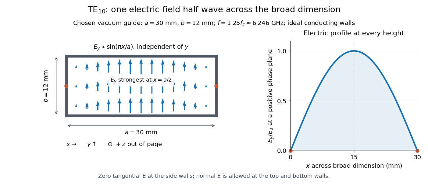
Original vacuum-filled rectangular guide: the TE10 electric-field profile across a 30 mm by 12 mm cross-section
. The arrows show the electric field at an axial plane and time where its common wave phase factor is positive; their length follows . They are field directions, not particle trajectories. The profile is uniform along and vanishes at the side walls. The guide axis points out of the cross-section. All dimensions and the operating frequency are chosen model values. Details.
For an original example choose , and , where . With , this givesHere is vacuum wavelength and is guided wavelength. The next cutoff is at ; starts at . Thus only can propagate at the chosen frequency, although a source or discontinuity can additionally excite local evanescent waves. These are calculated values, not specifications or measurements of a commercial guide.
An electromagnetic waveguide confines an electromagnetic wave across its axis while allowing it to travel along the axis. Conducting walls or changes of refractive index select transverse normal modes: reproducible cross-sectional field patterns with their own longitudinal wavenumbers. A hollow metal pipe and an optical fiber are different realizations of this principle. Their usefulness is to deliver electromagnetic energy along a chosen route instead of letting it spread freely.
For a uniform vacuum-filled conducting guide, write a normal mode's axial and time dependence as . Here is angular frequency, is the longitudinal wavenumber, and is the transverse eigenvalue selected by the wall boundary conditions. The electromagnetic wave equation separates intoThe geometry consumes part of the available squared wavenumber: when , this branch is an evanescent wave rather than a propagating normal mode. The waveguide cutoff frequency is therefore a property of a specified branch and geometry. A transverse electromagnetic mode in a suitable two-conductor geometry can have and no positive geometric cutoff. An optical fiber needs its own dielectric boundary conditions, rather than the metal-wall formulas below.
The rectangular electromagnetic waveguide makes these ideas explicit with a single sine profile. The scalar-potential conducting waveguide modes give a broader construction. At an open aperture, a confined field can radiate into the electromagnetic aperture angular spectrum; it need not remain one guided normal mode.
For a sphere of radius , the scattering efficiency is its effective scattering area divided by the projected geometric cross-section . It is a dimensionless quantity. For Rayleigh scattering by a small sphere with relative refractive index and incident wavenumber ,At fixed wavelength and fixed refractive index, the Rayleigh scattering cross-section scales as , whereas the scattering efficiency scales as . Doubling radius multiplies the former by and the latter by . An efficiency here is an effective scattering area relative to a reference area, rather than a fraction of all light in an arbitrary beam.
For a worked toy example, take , , and . Then and . Substitution gives Rayleigh scattering cross-section and scattering efficiency . At incident light intensity , the scattered power is approximately . These are leading small-particle estimates, not a measured air-molecule cross-section.
X-rays are high-frequency electromagnetic radiation, conventionally with wavelengths of roughly to . The precise wavelength convention varies with context. Hot accreting gas and energetic electronic processes can emit X-rays, whose short wavelengths make them useful probes of compact objects and electron shells.
For a photon, , where is the Planck constant and is the speed of light. As a calculated example, gives , using . The same wavelength can describe different production mechanisms: bremsstrahlung produces a continuous frequency spectrum, whereas Characteristic X-rays arise from discrete electronic changes in chemical atoms. Measuring transmitted X-rays gives radiography; measuring their frequency spectrum gives spectroscopy.
An RL circuit combines electrical resistance and self-inductance . In the series model, the same electric current flows through both components. An ideal battery maintains terminal electric potential difference ; the drops in the direction of positive electric current obey Ohm's law and the inductor relation:This is Kirchhoff's voltage law with the inductor's terminal drop, rather than its oppositely signed induced electromotive force. For constant , , and , the first-order linear differential equation has solutionThe time constant measures exponential decay of the difference from the final electric current. [ref].
For a stipulated example, take electrical resistance , self-inductance , terminal electric potential difference , and initial electric current . ThenWith measured numerically in seconds, this is in amperes. At one time constant,and the terminal electric potential difference drops areTheir sum is exactly . At , the inductor takes the entire terminal electric potential difference while the electric current is still zero. At steady electric current, the inductor's terminal drop is zero and the entire drop is across the electrical resistance.
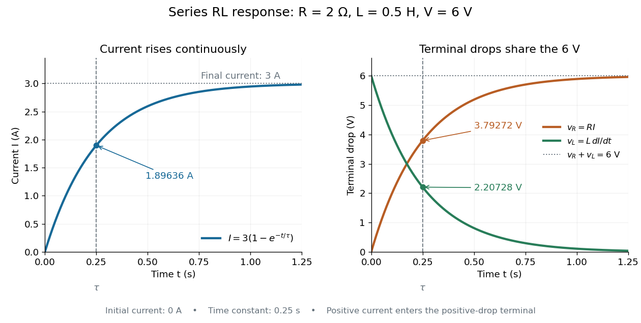

The final magnetic energy stored by the inductor is . At one time constant, the electric current has reached about of its final value, but its magnetic energy has reached only about :This difference follows from the square of electric current in the inductor's magnetic energy.
For release, take at the start of a separate experiment with initial electric current . Remove the battery from the model while maintaining a closed path through the same electrical resistance and inductor. ThenNow : the induced electromotive force supports the continuing positive electric current as its magnitude decreases. This closed-loop model describes exponential decay, not opening the sole path and imposing an instantaneous jump to zero electric current. The inductor's magnetic energy and the power of Joule heating areTheir time constant is . The total energy dissipated by Joule heating is exactly the initial magnetic energy:The second diagram in inductor shows this energy transfer. A finite closed path lets us predict both how long the electric current persists and how much energy becomes heat. [ref]
https://openstax.org/books/university-physics-volume-2/pages/14-4-rl-circuits. OpenStax University Physics 2, §14.4: decay in a closed RL loop
.An electric battery converts the available chemical Gibbs free energy of one or more galvanic cells into electrical work delivered to an electrical load. The reacting materials are a finite reservoir: a battery can sustain a terminal electric potential difference while discharging, but cannot supply energy indefinitely. Unlike a capacitor, whose capacitor energy resides in an electric field, a battery chiefly stores its available energy in the chemical state of its materials. The detailed half-reactions and apparatus of a Daniell cell explain this conversion at the electrode level.
During discharge, electrons move through metallic wires from the negative anode, through the electrical load, to the positive cathode; external conventional current points the other way. Inside the battery, ions carry electric current through the electrolyte, and redox chemical reactions connect ionic transport to electronic transport at the electrodes. The same electron does not make a lap through both wire and electrolyte. Electric charge conservation closes the circuit; changing chemical composition supplies the energy. See galvanic cell for the two transport paths and electrolyte for how oppositely moving ions contribute to one net electric current.
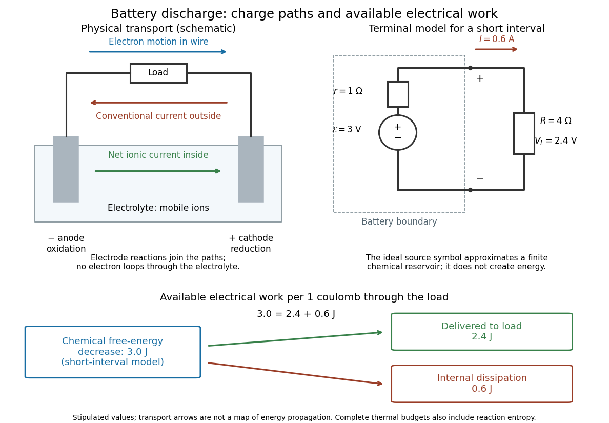

The source's electromotive force measures its driving work per unit electric charge, in volts; the loaded terminal electric potential difference measures the electrical work per unit electric charge delivered outside the battery. They agree in an ideal lossless source, or approximately near open circuit, but generally differ during discharge.[ref]
University Physics Volume 2 by Samuel J. Ling and others. §10.1, Introduction to Electromotive Force, work per charge and terminal voltage
In the ideal fixed-voltage model used in fixed-voltage capacitor energy balance, a battery maintains a prescribed terminal electric potential difference while electric charge flows to or from the capacitor. This is a constraint for that calculation, not an inexhaustible reservoir. The fixed-voltage capacitor energy balance also accounts for electrical energy returned to the source; an actual cell can accept sustained charging only if its chemistry and operating conditions permit it.
Electrical impedance is the ratio of terminal electric potential difference and electric current phasors at one specified positive angular frequency . For an electrical circuit modeled as a linear time-invariant system, use the sinusoidal steady state after any decaying transient has settled. With the passive sign convention, positive electric current enters the terminal assigned positive electric potential difference. Define peak complex amplitudes byThe physical and are real; the complex numbers encode their amplitudes and wave phases. The unit of electrical impedance is the ohm, . Both phasors may instead use root mean square magnitudes, with the same ratio . A nonlinear diode can generate additional frequencies; a single then does not describe the whole response.
Write the electrical impedance in Cartesian and polar forms asHere is the resistive real part, the signed electrical reactance, and the voltage-minus-current phase difference, defined modulo a full turn. The Pythagorean theorem gives the modulus from a right triangle in the complex plane. The complex argument gives the rotation from the current phasor to the voltage phasor. Thus , while negative means electric current leads terminal electric potential difference. For , lies between and ; outside that case, use the quadrant of the complex number rather than a bare inverse tangent. The geometric magnitude and phase difference are the two pieces of the AC relation.[ref]
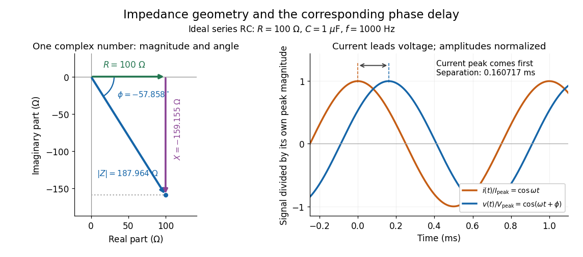

Multiplication by acts on phasors, not on instantaneous physical signals. For example, when ,The second term is in phase quadrature with electric current; it cannot be represented by pointwise multiplication when . This is the useful compression: one complex multiplication replaces separate amplitude and phase difference calculations, while the real part restores the physical signal.
An ideal resistor, inductor and capacitor have , and . Their electrical impedances add in a series RLC circuit, giving . The current amplitude is , so cancellation of the imaginary parts explains the resonant series RLC response. The component-law derivation and opposite complex exponential convention are in reactance phase convention.
The passive sign convention defines terminal electric potential difference and positive electric current entering at . Then is absorbed electrical power: positive means the component receives energy, negative means it supplies energy. Reversing both reference directions leaves the product unchanged. For a positive electrical resistance obeying Ohm's law, both and reverse together and Joule heating remains .
Electric flux measures how much electric field crosses a chosen oriented surface, with a sign distinguishing the two crossing directions. A strong electric field running along a surface contributes nothing to its electric flux: only the normal component counts. This lets Gauss's law turn a potentially complicated electric field into one number recording the net enclosed electric charge.
For a surface with chosen unit normal , the electric flux is the surface integralHere is positive surface area, while is the vector area element. The dot product makes electric flux a signed scalar, rather than a vector like the electric field. Its SI unit is : electric field measured using the newton per coulomb, multiplied by surface area in square metres. Reversing the orientation of a surface replaces by and reverses the electric flux. Calling it electric flux does not imply that electric charge is moving through the surface. [ref]
https://www.feynmanlectures.caltech.edu/II_03.html#Ch3-S2. Feynman lectures II.3, §3–2: flux of a vector field
.For an open patch in a plane, with surface area and a constant electric field, the unit normal is constant and the surface integral simplifies toThe angle is between the electric field and the chosen unit normal, not between the electric field and the plane. The cosine describes the signed projected surface area seen by the electric field. Thus electric flux is positive for , zero at , and negative for . [ref]
https://openstax.org/books/university-physics-volume-2/pages/6-1-electric-flux. Ling, Sanny and Moebs, University Physics II, §6.1: electric flux
.For example, take and , so . Three choices of angle giveKeeping the patch fixed and reversing its unit normal gives and changes to . The electric field and physical patch have not changed. If the electric field is instead tangent to the patch, its dot product with the unit normal vanishes: electric flux is zero even though .
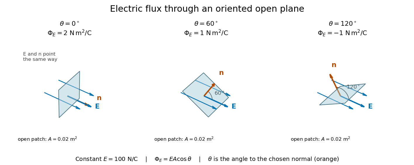
Three open patches in a plane in a constant electric field: the angle to the chosen unit normal gives electric fluxes of 2, 1 and minus 1 newton square metres per coulomb
. Details. 
For a closed surface enclosing a volume , choose the outward unit normal. Gauss's law givesHere is the vacuum permittivity, and is the signed total electric charge inside. The electric field in the surface integral includes all sources, including external electric charges. Assume no ideal point charge lies on the integration surface. Zero enclosed electric charge implies zero total electric flux; it does not imply zero electric field everywhere on the closed surface or inside it. Positive and negative contributions to the surface integral can cancel. [ref]
https://openstax.org/books/university-physics-volume-2/pages/6-2-explaining-gausss-law. Ling, Sanny and Moebs, University Physics II, §6.2: outward flux and enclosed charge
.To see the cancellation with sources inside, place point charges at and at , where , , and both lie inside the sphere of radius centered at the origin. This separated pair has the electric dipole geometry. Its enclosed electric charge is , so its total outward electric flux is zero. At the point on the sphere, Coulomb's law and the superposition principle give the individual electric fieldsThe components cancel and the positive components add:For the stipulated approximation and , this is about along positive . At , the outward unit normal is , so this nonzero electric field is tangent to the sphere. At other points of the sphere, its normal component can be positive or negative. The source-field formula applies away from the two point charges, where the electric field has zero divergence; it is singular at the sources. [ref]
https://www.feynmanlectures.caltech.edu/II_04.html#Ch4-S2. Feynman lectures II.4, §§4–1 and 4–2: electrostatic sources and superposition
.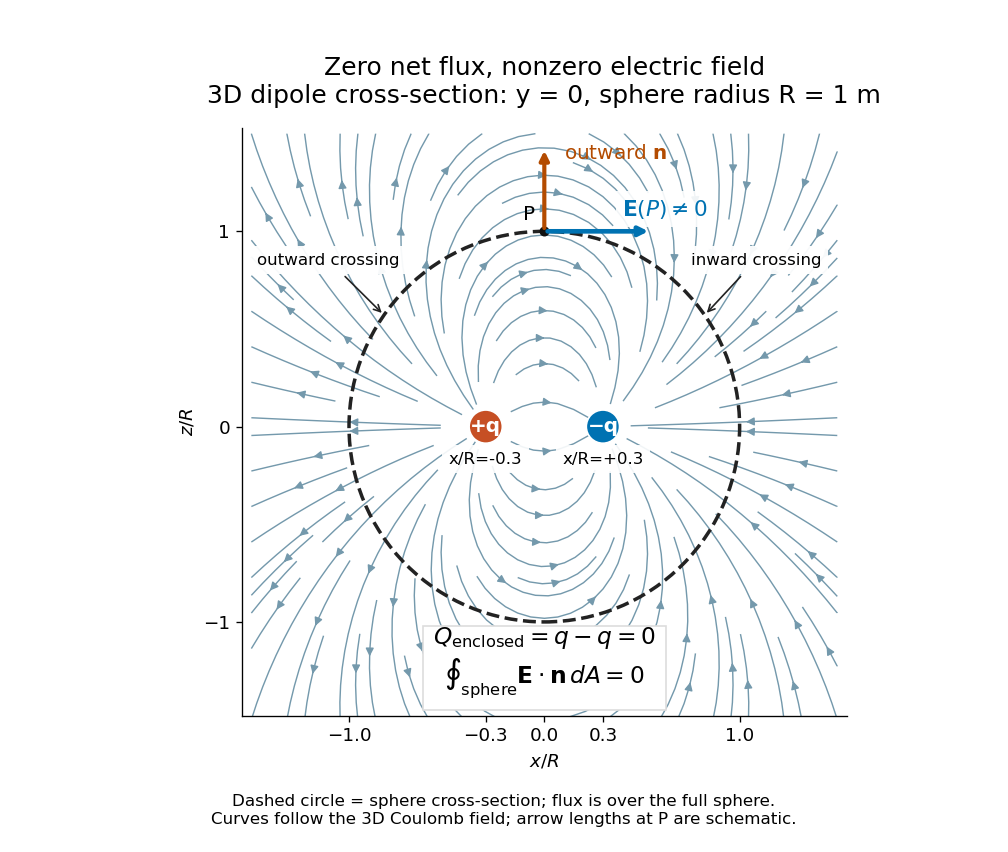
Cross-section of the three-dimensional electric field of two opposite point charges inside a unit-radius sphere: zero total electric flux coexists with a nonzero tangential electric field at the top
. Details. 
The diagram shows streamlines of the three-dimensional electric field in the section . The circle is a cross-section of the sphere, not the integration surface: Gauss's law uses the entire three-dimensional surface integral. A two-dimensional line integral of outward field around that circle would be a different quantity, with units rather than the electric flux units .
The electric force on an electric charge is , using the electric field of the other sources and excluding the charge's own self-field. Positive electric charge gives force along the electric field; negative electric charge reverses it. A field therefore gives on . This is the electric part of the Lorentz force; the magnetic contribution is . [ref].
There are unlisted articles, also show them or only show them.